EP0564751A1 - Hochauflösendes Digitalfilter - Google Patents
Hochauflösendes Digitalfilter Download PDFInfo
- Publication number
- EP0564751A1 EP0564751A1 EP92830177A EP92830177A EP0564751A1 EP 0564751 A1 EP0564751 A1 EP 0564751A1 EP 92830177 A EP92830177 A EP 92830177A EP 92830177 A EP92830177 A EP 92830177A EP 0564751 A1 EP0564751 A1 EP 0564751A1
- Authority
- EP
- European Patent Office
- Prior art keywords
- memories
- input
- signal
- digital filter
- digital
- Prior art date
- Legal status (The legal status is an assumption and is not a legal conclusion. Google has not performed a legal analysis and makes no representation as to the accuracy of the status listed.)
- Granted
Links
Images

Classifications
-
- H—ELECTRICITY
- H03—ELECTRONIC CIRCUITRY
- H03H—IMPEDANCE NETWORKS, e.g. RESONANT CIRCUITS; RESONATORS
- H03H17/00—Networks using digital techniques
- H03H17/02—Frequency selective networks
- H03H17/06—Non-recursive filters
- H03H17/0607—Non-recursive filters comprising a ROM addressed by the input data signals
Definitions
- This invention relates to a high-resolution digital filter of a type which comprises a memory structure receiving as input a sampled digital signal, and an adder chain, with delay blocks therebetween, which adders are connected to outputs of said memory in order to convert the input signal into an output signal having predetermined frequency response characteristics.
- the invention also concerns a method of filtering a sampled digital code signal.
- digital filters are devices intended for converting a sampled signal, receiving as input, into another sampled signal having predetermined frequency response characteristics.
- Sampled signal obviously means here a digital signal which is coded with a predetermined number n of bits on which the filter accuracy, or resolution, is dependent.
- Digital filters are primarily used in digital oscilloscopes, spectrum analyzers, and audio and video signal processors. Further, such filters are gaining increasing acceptance on account of a number of advantages that they afford over corresponding analog filters.
- digital filters allow of very narrow transmission bands, and are more stable both over time and vis- ⁇ -vis variations in the power supply and operating temperature.
- Digital filters have been implemented heretofore as integrated circuits employing digital multipliers and adders.
- Digital multipliers can be implemented with a non-volatile memory structure, such as a look-up table, wherein the products of the input signal samples by the coefficients of the filter transfer function are stored.
- n the number of bits used for sampling the input signal
- N the total number of the filter coefficients
- p the number of bits required to store the product of the samples by the coefficients
- a suitable, hypothetical memory structure would have to be a size sixteen times as large as that required by the former, 8-bits, coding. Such a memory would, therefore, occupy an inordinate amount of space in an integrated circuit. Moreover, it would lack adequate speed of data access because access time is heavily dependent on both the increased coding complexity and the memory size, specifically the number of bits per row.
- the underlying technical problem of this invention is to provide a digital filter, and associated filtering method, having such structural and functional features as to enable high-resolution processing of digital sampled signals coded with a large number of bits, thereby to overcome the limitations of the approaches currently proposed in the state of the art.
- the solutive idea on which this invention stands is one of splitting the sampled signal coding into at least two portions and then filtering each portion separately one from the other, to ultimately re-construct the sampled output signal.
- This filter 1 is input a given, digital code sampled signal x(n), and will output another sampled signal y(n) having predetermined frequency response characteristics.
- the filter 1 is of the linear phase, FIR (Finite Impulse Response) type, that is to say that the input signal x(n) and output signal y(n) are tied at any discrete time by the following relation: showing that the output sample y(n) is solely dependent on the current and past input samples.
- FIR Finite Impulse Response
- Equation (1) shows that an output sequence y(n) can be obtained from an input sequence x(n) by performing a series of products and sums on the samples that represent the impulse response of the system and the input samples as suitabled delayed.
- the filter 1 can be identified using a so-called transfer function H(z), as expressed versus a complex variable z, and defined as the ratio of the transform Z of a sequence of output signals y(nT) to the transform of a sequence of input signals x(nT):
- H(z) transfer function
- a circuit-wise synthesis of that transfer function practically enables the filter to be implemented in the form of an integrated circuit, using latches, digital multipliers, and adders arranged in such a way that for each input x(n) an output y(n) is produced in agreement with equation (1).
- FIG. 3 shown diagramatically in Figure 3 is a digital filter according to the prior art which utilizes a chain of N-1 adders (+), each having first and second inputs, and an output.
- the output of each adder is connected to the first input of the next adder via a delay block D.
- the second input of each adder is connected to the output of a corresponding multiplier X.
- Indicated at a(i) are the frequency response coefficients of the filter associated with the multipliers X.
- the aggregate of N multipliers X may be implemented in an integrated circuit with a memory structure,, e.g. a programmable read-only type, to whose inputs the signal x(n) is applied.
- a memory structure e.g. a programmable read-only type
- An example of this implementation is described in Italian Patent Application No. 22954-A/88.
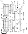
- said memory structure is implemented with at least one pair of non-volatile read-only memories 3 and 4.
- Each memory 3, 4 receives as input one portion of the sampled signal x(n).
- the first memory 3 receives the most significant portion x(n)1 of the digital coding of the sampled signal, whereas the other memory 4 receives the least significant portion x(n)2 of said coding.
- said memories are programmable read-only EPROM type, and additionally they are of the same size and contain the same data.
- Each memory is divided into cells or words 5 of p bits.
- Each word contains the result of the product of a single value of the input sample by a filter coefficient.
- a string of N words forms a memory row and there are 2 n/2 such rows.
- Each portion x(n)1, x(n)2 of the input signal is applied to the corresponding memory 3, 4 through a decoder 2.
- each memory On the output side of each memory is a read block 6 to which the N digital outputs 7 of each memory location pertaining to one coefficient are connected.
- a register 8 is provided after each read block 6. Further, an adder group 9 are cascaded to both registers 8 to receive the homolog outputs from such registers.
- a register 8 comprises a number of memory elements equal to the number of words in one row of memory 3 or 4, and the first adder 10 in the group 9 is connected to each first memory element of the registers 8, the second adder 11 to each second memory element, and so on.
- a buffer register 12 for storing the sum result therein.
- an adder chain 13 completes the filter 1 structure, and in a similar manner to prior approaches, enables the sampled signal y(n) to be output.
- This chain 13 has been also provided with an input IN for use where the filter 1 is to be connected in series with other filters having a similar structure.
- a generic sample of the input signal x(k) at time k is a binary number which is broken out into two contributions x(k)1+x(k)2 defining in terms of digital coding the most significant portion and the least significant portion, respectively, of the input sample. These contributions can be regarded as complementing each other, in the sense that their sum gives back the input sample.
- the memories 3 and 4 are divided into sections in which the product x(k)*ci is stored, where ci is the multiplicative coefficient of the i-th section.
- x(k)*ci (b0+b1*21+....+b (n/2)-1 *2 (n/2)-1 )*ci+(b n/2 +.
- the adder group 9 on the output side of the two memories 3 and 4 allows the signal to be restored to its complete coded state. The fact should not be overlooked, however, that the data output by one of the memories will be "shifted" by n/2 positions toward the most significant portion of the coding. Re-alignment will be provided by the adder group 9 itself.
- the digital filter of this invention has a major advantage in that it can occupy a uniquely small silicon space within an integrated circuit. This advantage reflects in a smooth circuit structure and constant response times being achieved.
Landscapes
- Physics & Mathematics (AREA)
- Engineering & Computer Science (AREA)
- Computer Hardware Design (AREA)
- Mathematical Physics (AREA)
- Complex Calculations (AREA)
- Filters That Use Time-Delay Elements (AREA)
Priority Applications (4)
| Application Number | Priority Date | Filing Date | Title |
|---|---|---|---|
| DE69222626T DE69222626T2 (de) | 1992-04-10 | 1992-04-10 | Hochauflösendes Digitalfilter |
| EP92830177A EP0564751B1 (de) | 1992-04-10 | 1992-04-10 | Hochauflösendes Digitalfilter |
| JP5083320A JPH06260890A (ja) | 1992-04-10 | 1993-04-09 | 高分解能ディジタルフィルタおよびディジタルコードサンプル信号のろ波方法 |
| US08/384,211 US5563816A (en) | 1992-04-10 | 1995-02-06 | High-resolution digital filter |
Applications Claiming Priority (1)
| Application Number | Priority Date | Filing Date | Title |
|---|---|---|---|
| EP92830177A EP0564751B1 (de) | 1992-04-10 | 1992-04-10 | Hochauflösendes Digitalfilter |
Publications (2)
| Publication Number | Publication Date |
|---|---|
| EP0564751A1 true EP0564751A1 (de) | 1993-10-13 |
| EP0564751B1 EP0564751B1 (de) | 1997-10-08 |
Family
ID=8212087
Family Applications (1)
| Application Number | Title | Priority Date | Filing Date |
|---|---|---|---|
| EP92830177A Expired - Lifetime EP0564751B1 (de) | 1992-04-10 | 1992-04-10 | Hochauflösendes Digitalfilter |
Country Status (4)
| Country | Link |
|---|---|
| US (1) | US5563816A (de) |
| EP (1) | EP0564751B1 (de) |
| JP (1) | JPH06260890A (de) |
| DE (1) | DE69222626T2 (de) |
Cited By (2)
| Publication number | Priority date | Publication date | Assignee | Title |
|---|---|---|---|---|
| US5586068A (en) * | 1993-12-08 | 1996-12-17 | Terayon Corporation | Adaptive electronic filter |
| US5894495A (en) * | 1996-06-10 | 1999-04-13 | Toshiba Electronics Europe Gmbh | Adaptive digital filter |
Families Citing this family (5)
| Publication number | Priority date | Publication date | Assignee | Title |
|---|---|---|---|---|
| US5838725A (en) * | 1996-12-06 | 1998-11-17 | U.S. Philips Corporation | Floating point digital transversal filter |
| US6243729B1 (en) * | 1998-12-31 | 2001-06-05 | Texas Instruments Incorporated | Digital finite-impulse-response (FIR) filter with a modified architecture based on high order Radix-N numbering |
| US6735607B2 (en) * | 2001-06-02 | 2004-05-11 | Lockheed Martin Corporation | Transparent data access and interpolation apparatus and method therefor |
| US7366746B2 (en) * | 2004-02-12 | 2008-04-29 | Xerox Corporation | Finite impulse response filter method and apparatus |
| US20070112901A1 (en) * | 2005-11-15 | 2007-05-17 | Afshin Niktash | Configurable digital filter |
Citations (1)
| Publication number | Priority date | Publication date | Assignee | Title |
|---|---|---|---|---|
| EP0078101A2 (de) * | 1981-10-27 | 1983-05-04 | Itt Industries, Inc. | Multiplikationseinrichtung zur Bildung einer Produktensumme |
Family Cites Families (8)
| Publication number | Priority date | Publication date | Assignee | Title |
|---|---|---|---|---|
| DE3142058A1 (de) * | 1981-10-23 | 1983-05-05 | Elektroschmelzwerk Kempten GmbH, 8000 München | Praktisch porenfreie formkoerper aus polykristallinem siliciumnitrid und siliciumcarbid und verfahren zu ihrer herstellung durch isostatisches heisspressen |
| FR2557746B1 (fr) * | 1983-12-30 | 1986-04-11 | Thomson Csf | Filtre numerique a bande passante et phase variables |
| JPS62118630A (ja) * | 1985-11-19 | 1987-05-30 | Nec Corp | デイジタルフイルタ |
| US4811262A (en) * | 1986-09-19 | 1989-03-07 | Rockwell International Corporation | Distributed arithmetic realization of second-order normal-form digital filter |
| US5053984A (en) * | 1989-11-21 | 1991-10-01 | Sgs Thomson Microelectronics S.R.L. | Memory for programmable digital filter |
| JPH02256307A (ja) * | 1989-03-29 | 1990-10-17 | Toshiba Corp | バイナリトランスバーサルフィルタ |
| JPH02287874A (ja) * | 1989-04-28 | 1990-11-27 | Toshiba Corp | 積和演算装置 |
| US5117385A (en) * | 1990-03-16 | 1992-05-26 | International Business Machines Corporation | Table lookup multiplier with digital filter |
-
1992
- 1992-04-10 EP EP92830177A patent/EP0564751B1/de not_active Expired - Lifetime
- 1992-04-10 DE DE69222626T patent/DE69222626T2/de not_active Expired - Fee Related
-
1993
- 1993-04-09 JP JP5083320A patent/JPH06260890A/ja active Pending
-
1995
- 1995-02-06 US US08/384,211 patent/US5563816A/en not_active Expired - Lifetime
Patent Citations (1)
| Publication number | Priority date | Publication date | Assignee | Title |
|---|---|---|---|---|
| EP0078101A2 (de) * | 1981-10-27 | 1983-05-04 | Itt Industries, Inc. | Multiplikationseinrichtung zur Bildung einer Produktensumme |
Non-Patent Citations (2)
| Title |
|---|
| GOLLA C., ET AL.: "30-MSAMPLES/S PROGRAMMABLE FILTER PROCESSOR.", IEEE JOURNAL OF SOLID-STATE CIRCUITS., IEEE SERVICE CENTER, PISCATAWAY, NJ, USA, vol. 25., no. 06., 1 December 1990 (1990-12-01), PISCATAWAY, NJ, USA, pages 1502 - 1509., XP000176581, ISSN: 0018-9200, DOI: 10.1109/4.62186 * |
| SILLER JR. C. A., DEBUS JR. W.: "APPLICATION OF MEMORY-BASED DIGITAL FILTERING TO HIGH-SPEED DIGITAL RADIO.", AT & T TECHNICAL JOURNAL., AMERICAN TELEPHONE AND TELEGRAPH CO. NEW YORK., US, vol. 69., no. 05., 1 September 1990 (1990-09-01), US, pages 100 - 115., XP000224083, ISSN: 8756-2324 * |
Cited By (2)
| Publication number | Priority date | Publication date | Assignee | Title |
|---|---|---|---|---|
| US5586068A (en) * | 1993-12-08 | 1996-12-17 | Terayon Corporation | Adaptive electronic filter |
| US5894495A (en) * | 1996-06-10 | 1999-04-13 | Toshiba Electronics Europe Gmbh | Adaptive digital filter |
Also Published As
| Publication number | Publication date |
|---|---|
| JPH06260890A (ja) | 1994-09-16 |
| DE69222626D1 (de) | 1997-11-13 |
| EP0564751B1 (de) | 1997-10-08 |
| DE69222626T2 (de) | 1998-02-05 |
| US5563816A (en) | 1996-10-08 |
Similar Documents
| Publication | Publication Date | Title |
|---|---|---|
| US6888372B1 (en) | Programmable logic device with soft multiplier | |
| EP0372350B1 (de) | Programmierbares digitales Filter | |
| US4598266A (en) | Modulo adder | |
| JPH09135149A (ja) | 広帯域デジタルろ波方法およびこの方法を使用したフィルタ | |
| EP0476215A1 (de) | Mehrkanaliger Taktfrequenzreduzierer | |
| US4337518A (en) | Recursive-type digital filter with reduced round-off noise | |
| US4323980A (en) | Digital filter for shared-time processing on several channels | |
| US4791597A (en) | Multiplierless FIR digital filter with two to the Nth power coefficients | |
| US4340781A (en) | Speech analysing device | |
| US3988606A (en) | Digital filter device for processing binary-coded signal samples | |
| EP0564751B1 (de) | Hochauflösendes Digitalfilter | |
| US4831574A (en) | Device for computing a digital transform of a signal | |
| EP0021018A1 (de) | Digitale Filter | |
| JPH0831776B2 (ja) | デジタルフイルタ | |
| US4588980A (en) | Residue to analog converter | |
| US4052605A (en) | Interpolating non-recursive digital filter | |
| EP0608665B1 (de) | Verfahren zur Filterung von hochauflösenden digitalen Signalen und entsprechende digitale Filterarchitektur | |
| JPS6346608B2 (de) | ||
| US4584561A (en) | Method of residue to analog conversion | |
| EP0266004B1 (de) | Digitales, nicht-rekursives Filter mit Multiplizierkoeffizienten der Basis zwei | |
| US4584563A (en) | Method of residue to analog conversion | |
| US5053984A (en) | Memory for programmable digital filter | |
| US4584564A (en) | Residue to analog converter | |
| US5128886A (en) | Using long distance filters in the presence of round-off errors | |
| US4584562A (en) | Method of residue to analog conversion |
Legal Events
| Date | Code | Title | Description |
|---|---|---|---|
| PUAI | Public reference made under article 153(3) epc to a published international application that has entered the european phase |
Free format text: ORIGINAL CODE: 0009012 |
|
| AK | Designated contracting states |
Kind code of ref document: A1 Designated state(s): DE FR GB IT SE |
|
| RBV | Designated contracting states (corrected) |
Designated state(s): DE FR GB IT |
|
| 17P | Request for examination filed |
Effective date: 19940324 |
|
| 17Q | First examination report despatched |
Effective date: 19960213 |
|
| GRAG | Despatch of communication of intention to grant |
Free format text: ORIGINAL CODE: EPIDOS AGRA |
|
| GRAH | Despatch of communication of intention to grant a patent |
Free format text: ORIGINAL CODE: EPIDOS IGRA |
|
| GRAH | Despatch of communication of intention to grant a patent |
Free format text: ORIGINAL CODE: EPIDOS IGRA |
|
| GRAA | (expected) grant |
Free format text: ORIGINAL CODE: 0009210 |
|
| AK | Designated contracting states |
Kind code of ref document: B1 Designated state(s): DE FR GB IT |
|
| REF | Corresponds to: |
Ref document number: 69222626 Country of ref document: DE Date of ref document: 19971113 |
|
| ET | Fr: translation filed | ||
| PLBE | No opposition filed within time limit |
Free format text: ORIGINAL CODE: 0009261 |
|
| RAP4 | Party data changed (patent owner data changed or rights of a patent transferred) |
Owner name: STMICROELECTRONICS S.R.L. |
|
| 26N | No opposition filed | ||
| REG | Reference to a national code |
Ref country code: GB Ref legal event code: IF02 |
|
| PGFP | Annual fee paid to national office [announced via postgrant information from national office to epo] |
Ref country code: DE Payment date: 20020417 Year of fee payment: 11 |
|
| PG25 | Lapsed in a contracting state [announced via postgrant information from national office to epo] |
Ref country code: DE Free format text: LAPSE BECAUSE OF NON-PAYMENT OF DUE FEES Effective date: 20031101 |
|
| PGFP | Annual fee paid to national office [announced via postgrant information from national office to epo] |
Ref country code: GB Payment date: 20040407 Year of fee payment: 13 |
|
| PGFP | Annual fee paid to national office [announced via postgrant information from national office to epo] |
Ref country code: FR Payment date: 20040408 Year of fee payment: 13 |
|
| PG25 | Lapsed in a contracting state [announced via postgrant information from national office to epo] |
Ref country code: IT Free format text: LAPSE BECAUSE OF NON-PAYMENT OF DUE FEES;WARNING: LAPSES OF ITALIAN PATENTS WITH EFFECTIVE DATE BEFORE 2007 MAY HAVE OCCURRED AT ANY TIME BEFORE 2007. THE CORRECT EFFECTIVE DATE MAY BE DIFFERENT FROM THE ONE RECORDED. Effective date: 20050410 Ref country code: GB Free format text: LAPSE BECAUSE OF NON-PAYMENT OF DUE FEES Effective date: 20050410 |
|
| GBPC | Gb: european patent ceased through non-payment of renewal fee |
Effective date: 20050410 |
|
| PG25 | Lapsed in a contracting state [announced via postgrant information from national office to epo] |
Ref country code: FR Free format text: LAPSE BECAUSE OF NON-PAYMENT OF DUE FEES Effective date: 20051230 |
|
| REG | Reference to a national code |
Ref country code: FR Ref legal event code: ST Effective date: 20051230 |