EP0564812A1 - Procédé et dispositif pour ouvrir des produits d'imprimerie pliés - Google Patents
Procédé et dispositif pour ouvrir des produits d'imprimerie pliés Download PDFInfo
- Publication number
- EP0564812A1 EP0564812A1 EP93103235A EP93103235A EP0564812A1 EP 0564812 A1 EP0564812 A1 EP 0564812A1 EP 93103235 A EP93103235 A EP 93103235A EP 93103235 A EP93103235 A EP 93103235A EP 0564812 A1 EP0564812 A1 EP 0564812A1
- Authority
- EP
- European Patent Office
- Prior art keywords
- gripper
- product part
- conveying direction
- product
- printed products
- Prior art date
- Legal status (The legal status is an assumption and is not a legal conclusion. Google has not performed a legal analysis and makes no representation as to the accuracy of the status listed.)
- Granted
Links
- 238000000034 method Methods 0.000 title claims description 17
- 238000005452 bending Methods 0.000 claims description 4
- 230000001360 synchronised effect Effects 0.000 claims description 2
- 238000011144 upstream manufacturing Methods 0.000 description 5
- 230000006835 compression Effects 0.000 description 3
- 238000007906 compression Methods 0.000 description 3
- 230000003319 supportive effect Effects 0.000 description 2
- 230000006978 adaptation Effects 0.000 description 1
- 230000001419 dependent effect Effects 0.000 description 1
- 230000005484 gravity Effects 0.000 description 1
- 230000000284 resting effect Effects 0.000 description 1
- 238000000926 separation method Methods 0.000 description 1
Images




Classifications
-
- B—PERFORMING OPERATIONS; TRANSPORTING
- B65—CONVEYING; PACKING; STORING; HANDLING THIN OR FILAMENTARY MATERIAL
- B65H—HANDLING THIN OR FILAMENTARY MATERIAL, e.g. SHEETS, WEBS, CABLES
- B65H5/00—Feeding articles separated from piles; Feeding articles to machines
- B65H5/30—Opening devices for folded sheets or signatures
- B65H5/308—Opening devices for folded sheets or signatures the folded sheets or signatures travelling in hanging position
-
- B—PERFORMING OPERATIONS; TRANSPORTING
- B65—CONVEYING; PACKING; STORING; HANDLING THIN OR FILAMENTARY MATERIAL
- B65H—HANDLING THIN OR FILAMENTARY MATERIAL, e.g. SHEETS, WEBS, CABLES
- B65H29/00—Delivering or advancing articles from machines; Advancing articles to or into piles
- B65H29/003—Delivering or advancing articles from machines; Advancing articles to or into piles by grippers
-
- B—PERFORMING OPERATIONS; TRANSPORTING
- B65—CONVEYING; PACKING; STORING; HANDLING THIN OR FILAMENTARY MATERIAL
- B65H—HANDLING THIN OR FILAMENTARY MATERIAL, e.g. SHEETS, WEBS, CABLES
- B65H5/00—Feeding articles separated from piles; Feeding articles to machines
- B65H5/32—Saddle-like members over which partially-unfolded sheets or signatures are fed to signature-gathering, stitching, or like machines
-
- B—PERFORMING OPERATIONS; TRANSPORTING
- B65—CONVEYING; PACKING; STORING; HANDLING THIN OR FILAMENTARY MATERIAL
- B65H—HANDLING THIN OR FILAMENTARY MATERIAL, e.g. SHEETS, WEBS, CABLES
- B65H2301/00—Handling processes for sheets or webs
- B65H2301/30—Orientation, displacement, position of the handled material
- B65H2301/32—Orientation of handled material
- B65H2301/323—Hanging
-
- B—PERFORMING OPERATIONS; TRANSPORTING
- B65—CONVEYING; PACKING; STORING; HANDLING THIN OR FILAMENTARY MATERIAL
- B65H—HANDLING THIN OR FILAMENTARY MATERIAL, e.g. SHEETS, WEBS, CABLES
- B65H2301/00—Handling processes for sheets or webs
- B65H2301/40—Type of handling process
- B65H2301/44—Moving, forwarding, guiding material
- B65H2301/447—Moving, forwarding, guiding material transferring material between transport devices
- B65H2301/4471—Grippers, e.g. moved in paths enclosing an area
- B65H2301/44712—Grippers, e.g. moved in paths enclosing an area carried by chains or bands
-
- B—PERFORMING OPERATIONS; TRANSPORTING
- B65—CONVEYING; PACKING; STORING; HANDLING THIN OR FILAMENTARY MATERIAL
- B65H—HANDLING THIN OR FILAMENTARY MATERIAL, e.g. SHEETS, WEBS, CABLES
- B65H2301/00—Handling processes for sheets or webs
- B65H2301/40—Type of handling process
- B65H2301/44—Moving, forwarding, guiding material
- B65H2301/447—Moving, forwarding, guiding material transferring material between transport devices
- B65H2301/44795—Saddle conveyor with saddle member extending transversally to transport direction
Definitions
- the present invention relates to a method and a device for opening folded printed products, in particular newspapers, magazines and parts thereof, according to the preamble of claims 1 and 7, respectively.
- the upper part of the product has an edge section in the end region, which protrudes beyond the shorter, lower part of the product.
- This edge section is gripped by a gripper of the opening device and clamped between itself and the belt, and the shorter, lower part of the product is moved in the direction of conveyance by the faster running small conveyor belt moved away from the held part of the product with bulging and thus opened the printed product.
- a collecting bar of a collecting device runs into the opened printed product between the separated parts of the product and after the release of the printed products by the transport clips, they fall astride the collecting bars.
- EP-A-0 208 081 and the corresponding US-A-4,684,117 disclose a method and a device for opening eccentrically folded printed products with a fold trailing in the conveying direction and a leading edge region opposite the fold.
- the printed products are held by individually controllable grippers of a conveying device and transported with the conveying direction running obliquely from above to below.
- An opening device is provided below the conveying device, which has grippers arranged on a rotatingly driven pulling element.
- a fixed support plate is provided to the side of the traction element and this is preceded by an endless support belt driven in rotation in order to support the printed products in the leading end region.
- the edge section under which a gripping tongue of the gripper is opened is raised and the relevant transport clamp is briefly opened, so that the shorter product part below slides into the effective area of the gripper.
- the shorter product part held thereby is again deflected in a direction transverse to the conveying direction when the gripper rotates around the deflection wheel and is moved away from the non-held product part above to open the printed product.
- the abutting product parts of the printed products supported in their end area are lifted away from each other transversely to the conveying direction. This only has to be done in a small area, so that the product parts can be gripped easily by appropriate grippers of the opening device. Due to the grippers being driven at different speeds, the end edges of the product parts are now moved away from each other in the conveying direction. Since the product parts are held by the grippers, a forced separation of the product parts from one another is ensured, even if they should stick to one another. Since the grippers are moved in the conveying direction, there is a considerable amount of time available for opening. Furthermore, at least one of the product parts is bulged or brought into a position that is more stretched with respect to the other product part, so that the product parts are lifted from one another not only in the end region but up to the transport clamp.
- the product part located at the top is raised, which can take place when the gripper assigned to the product part located at the bottom is opened by its moving clamping tongue engaging under the upper product part.
- the opening device can thereby be particularly simple. If the product part with the edge section lying on top, it is easy to reach under the edge section, especially if the end edge of the printed product is brought into abutment against a stop on the gripper. The position of the end section is then precisely defined with respect to the clamping tongue.
- the bottom product part is bulged in the end area against the top product part, so that the top product part lifts off from the bottom product part due to its inherent rigidity. Since this lifting off only has to take place along a small section of the end edge of the product part, it is also guaranteed for printed products with low inherent rigidity.
- the bulging of the underlying product part of printed products which are held in their fold and are supported in the end region in such a way that they are bent can be done in a simple manner in that the edge section is bent on one side towards the bottom and with its end edge in the direction is pushed against the end edge of the overhead product part. It is possible that the top part of the product is now gripped directly by the corresponding gripper, without that being raised further by means of the clamping tongue of the gripper assigned to the bottom part of the product.
- the device has a conveyor device 10 of a generally known type with transport brackets 14 arranged one behind the other at a fixed distance A on a chain conveyor 12 indicated by dash-dotted lines.
- the conveyor chain 12 is guided in a C-shaped channel 16 which is open towards the bottom and extends in the horizontal direction.
- the transport clamps 14, which are driven continuously rotating in the conveying direction F at a conveying speed v, have a downward-directed in the vertical direction Clamping mouth 18 with which they hold a folded printed product 20, preferably a multi-leaf newspaper, magazine or parts thereof, at the fold 22 running at right angles to the conveying direction.
- an opening device 24 which has a support element 26 running parallel to the conveying direction F, on which the printed products 20 lie flat with their end region 28 facing away from the fold 22.
- the printed products 20 hanging freely on the transport clamps 14 are bent backwards when they run onto the support element 26, which in the present case is formed by a fixed support member 30, as can be clearly seen from FIGS. 1 and 2.
- the printed products 20 are folded off-center.
- the one longer product part 32 has in the end region 28 an edge section 34 which protrudes over the other shorter product part 36.
- the printed products 20 are conveyed in such a way that the shorter product part 36 is leading and thus in the region of the support member 30 the longer product part 32 with the edge section 34 is on top.
- the opening device 24 is only so far from the conveying device 10 in the vertical direction that the printed products 20 can rest with their end region 28 on the support element 26.
- the opening device 24 is adjustable in the vertical direction.
- the opening device 24 has the respective lower product part, in the present case the first gripper 38 assigned to the shorter product part 36 and the respective upper product part, in the present case the second gripper 40 assigned to the longer product part 32.
- a plurality of first grippers 38 are arranged on an endless first traction element 42, preferably a chain, at a fixed distance B which is greater than the distance A between the transport clips 14 (FIG. 1).
- a plurality of second grippers 40 are arranged on a second pulling element 44, likewise preferably a chain, at a fixed distance C which corresponds approximately to the distance A between the transport clips 14.
- the traction elements 42, 44 run in mutually parallel planes and the active strands run side by side and parallel to the conveying direction F.
- the traction elements 42, 44 are each by three deflection wheels 46, 46 ', 48, 48', 50, 50 'which are mounted on the same axis. guided, the deflecting wheels 46, 48 'and 46', 48 'delimiting the active strands 42', 44 'in the present case having the same diameter, whereas the deflecting wheel 50, around which the rear strand of the first pulling element 42 is guided, has a larger one Has a diameter than the deflection wheel 50 'around which the rear run of the second tension member 44 runs. The ratio of these diameters is equal to the ratio of the distance B to the distance C. Since the deflection wheels 50, 50 'sit on a common drive shaft 52 in a rotationally fixed manner (FIGS.
- the ratio is the circulation speed vl of the first pulling element 42 and the first grippers 38 to the speed v2 of the second pulling element 44 and the second grippers 40 is equal to the ratio between the distance B between the first grippers 38 and the distance C between the second grippers 40.
- One deflection wheel 50 or 50 'or both deflection wheels 50, 50' can be arranged on the drive shaft 52 so as to be adjustable in the direction of rotation in order to adjust the phase position between the first and second pulling elements 42, 44 and the conveyor device 10, so that in each case at the desired location, Viewed in the direction of conveyance F, a first gripper 38 and a second gripper 40 are located next to one another in the initial region of the active runs 42 ', 44', as is clearly shown in FIG. 1.
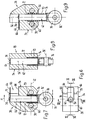
- the first gripper 38 has a gripper body 54, through which an essentially cylindrical passage 56 runs.
- the axis 56 'of the passage 56 extends at right angles to the first tension member 42, which is indicated by dash-dotted lines in FIG. 7.
- the gripper body 54 is connected in a rotationally fixed manner to the first pulling element 42 by means of two fastening bolts 58 which pass through the gripper body 54 through corresponding bores 60.
- a shaft 62 is guided in the passage 56 so as to be displaceable in the direction of the axis 56 '.
- a sheet-like clamping tongue 64 protrudes from the shaft 62 and interacts with a clamping jaw 66 formed on the gripper body 54.
- the clamping tongue 64 and clamping jaw 66 form a gripper jaw 68 which, in the opening device 24 according to FIGS. 1-4, is directed forward in the conveying direction.
- the first grippers 38 can be arranged reversely on the pulling element 42, so that the gripper mouth 68 is directed against the conveying direction F.
- the clamping tongue 64 is pretensioned in the closing direction by means of a compression spring 70 which engages around the shaft 62 and is supported on the top on a shoulder 72 of the gripper body 54 and at the bottom on a counter shoulder 74 on the shaft 62.
- the closed position of the first gripper 38 is shown in FIG. 9.
- a control roller 76 is freely rotatably mounted on the shaft 62 about an axis 76 'running at right angles to the axis 56' and at right angles to the conveying direction F.
- an opening link 78 By means of an opening link 78, the shaft 62 can be raised at right angles to the conveying direction F against the force of the compression spring 70, so that the clamping tongue 64 can be moved into the open position shown in FIG. 7.
- a stop is designated which limits the gripper mouth 68.
- the second gripper 40 is constructed similarly to the first gripper 38, as can be seen in particular from FIGS. 10-13.
- a gripper body 80 also has a substantially cylindrical passage 82, the axis of which is designated 82 '.
- a shaft 84 is also guided in the passage 82 so as to be displaceable in the direction of the axis 82 ′.
- the gripper body In the upper end region of the gripper body 80, the gripper body has a fixed gripper jaw 86 which, viewed in the conveying direction F, projects like a nose.
- Adjoining the gripper jaw 86 in the gripper body 80 is a guide slot 88 which extends in the direction of the axis 82 'and in which a clamping pin 90 is guided which penetrates the shaft 84 at right angles to the axis 82'.
- the Clamping pin 90 acts as a movable gripper jaw with the fixed gripper jaw 86, these form a gripper jaw, designated 92, which, in the opening device 24 according to FIGS. 1-5 viewed in the conveying direction F, is directed forward in the region of the conveying strand 44 '.
- These second grippers 40 can also be arranged on the second pulling element 44, so that the gripper mouth 92 is directed counter to the conveying direction F, as is described further below in connection with FIGS. 27 and 28.
- the upper end of the clamping pin 90 supports a closing spring 94 designed as a compression spring, which engages around the shaft 84 and is supported at the bottom on a gripper body shoulder 96.
- the closing spring 94 urges the clamping pin 90 against the fixed gripper jaw 86 in the closing direction.
- the closed position of the second gripper 40 is shown in FIG. 13.
- a bearing shaft 98 protrudes radially from the shaft 84, which penetrates an elongated hole-like opening 100 in the gripper body 80 and on which a control roller 102 is likewise freely rotatably mounted outside the gripper body 80.
- the clamping pin 90 can be moved against the force of the closing spring 94 into the open position shown in FIG. 11 by means of a further opening link designated 104 (FIG. 12).
- the gripper body 80 is fastened to the second pulling element 44 by means of a single fastening bolt 106 (see also FIG. 5), the fastening bolt 106 fastening the gripper body 80 penetrates through a bore 108, the axis of which is perpendicular to the axis 82 'and perpendicular to the conveying direction F.
- the bore 108 is offset forward in the conveying direction F with respect to the center of gravity of the second gripper 40, so that the second gripper 40, which is pivotably arranged in the second traction element 44, has the tendency in the region of the active run 44 ′ to move backwards, counterclockwise swivel. Therefore, the gripper body 80 is designed in its lower end region 80 'as a sliding shoe which interacts with a swivel link 110 provided in the region of the active run 44'.
- the shape and position of the opening link 78 interacting with the first gripper 38 and the opening link 104 and pivot link 110 acting on the second gripper 40 can be seen in FIGS. 1, 2, 4 and 5.
- the swivel link 110 begins in the conveying direction F following the deflection wheel 46 'and extends into the area of the deflection wheel 48'.
- the opening link 104 for the second gripper 40 is provided in the initial region of this pivot link 110 and above it.
- the opening backdrop 78 for the first gripper 38 is located adjacent to the opening backdrop 104.
- the opening device 24 has two cross members 114 interconnected bearing plates 116, on which the opening links 78, 78 ', 104, 104' via the shaft of the deflecting wheels 48, 48 'and the pivoting link 110 are optionally adjustably attached.
- a guide rail 118 is supported on the crossbeams 114, in which the traction elements 42, 44 designed as chains are guided in the area between the deflection wheels 46, 46 'and 48, 48'.
- the support member 30 designed as a support plate 120 is also fastened by this guide rail 118 and on the bearing plate 116 on the left in FIG. 3. This supports the printed products 20, as shown in FIG.
- the support plate 120 has a slot running in the conveying direction, which is penetrated by the second grippers 40 when they are in the region of the active strand 44 '.
- the first traction element 42 is guided in the region of the active run 42 ′ in such a way that the clamping jaw 66 of the first grippers 38 is approximately aligned with the upper surface of the support plate 120.
- the fixed gripper jaw 86 of the second gripper 40 viewed in the vertical direction, is at a greater distance from the support plate 120 than the upper end of the first gripper 38.
- the clamping pin 90 of the second gripper 40 is in the open position, this is seen below the upper one in the vertical direction Arranged end of the first gripper 38.
- the path of movement of the gripper mouth 92 when the second gripper 40 is closed therefore runs above the first grippers 38; this is always seen in the area of the active dreams 42 ', 44'.
- the endless chain 126 is driven in the circumferential direction U at a speed which corresponds to the conveying speed v of the conveying device 10 or preferably at a higher speed in order to keep the opened printed products 20 open during further transport and, if appropriate, the leading product part 36 even further from the trailing product part 32 to take off.
- the opening device 24 is followed by a collecting device 134, which has a multiplicity of collecting webs 136 which rotate in the direction of rotation D about a common rotational axis (not shown in FIGS. 1 and 2).
- a collecting web 136 engages from below into a printed product 20 opened by the opening device 24 and kept open by the holding device 124, and after opening the corresponding transport clamp 14 by means of an opening element 138, the printing product 20 in question straddles the saddle-shaped collecting web 136 in question.
- the collecting webs 136 can have means of transport in order to shift the stored printed products 20 in their longitudinal direction.
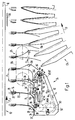
- FIGS. 14-18 show the first gripper 38 and the second gripper 40 in the initial area of the pivot link 110 and in the area of the opening link 78 and 104 at five successive times.
- the position shown in FIG. 14 is taken up by the grippers 38, 40 in the initial area of the active dreams 42 ', 44', as is also the case in FIG 42 ', 44' can be seen.
- the clamping tongue 64 of the first gripper 38 is in the closed position, whereas the clamping pin 90 of the second gripper 40 has already been transferred to the open position.
- the second gripper 40 assumes a position inclined backwards. Due to its speed v1, which is greater than the conveying speed v of the conveying device 10, the first gripper 38 now picks up the printed product 20, which rests with its end region 28 on the support plate 120, so that the end edge of the overhead product part 32 on the stop 79 of the gripper body 54 comes to rest, as shown in FIG. 15. Now the clamping tongue 64 of the first gripper 38 is moved into the open position as a result of the action of the opening link 78, whereby it engages under and raises the edge section 34 of the product part 32 located above, as shown in FIG. 16.
- the second gripper 40 runs onto the pivot link 110, whereby it is pivoted forward in a clockwise direction, into a position in which the axis 82 '(compare FIGS. 10-13) runs approximately in the vertical direction and thus approximately at right angles to the conveying direction F.
- the gripper mouth 92 now catches up with the edge section 34 in order to clamp it between the gripper jaw 86 and the clamping pin 90 when the second gripper 40 is subsequently closed.
- the clamping tongue 64 is transferred into the closed position, as a result of which the product part 36 located below is clamped at its end edge 32 '.
- the first gripper 38 is then opened as a result of the action of the opening link 78 ′ and the product part 36 is released (FIG. 1).
- the relevant second gripper 40 is then deflected by the deflection wheel 48 ', its gripper mouth 92 is opened under the action of the opening link 104' and the other product part 32 is released (FIG. 2).
- the first gripper 38 has a bending element 142 designed as a pivot cam 140, as can be seen from FIG. 3 and FIGS. 19-24.
- the double-armed swivel cam 140 is pivotally mounted on the rear fastening bolt 58 of the gripper body 54, as seen in the conveying direction F, and by means of a swivel link 144 (FIGS. 3 and 24) from a rest position (FIGS. 21-23) into a working position, as shown in FIGS.
- pivot link 144 can be moved out of the area of action on the pivot cam 140 and the mode of operation of the first gripper 38 is exactly the same as that described above with reference to FIGS. 1-18.
- the swivel cam 140 brought into the working position produces a stop which is leading in relation to the stop 79 on the gripper body 54.
- This causes an impact force on the end edge 32 'of the edge section 34 and, as a result of the front edge of the pivot cam 140 which is sloping towards the rear, the edge section 34 and a region adjoining it are bent downward along the side edge 122' and forward in the conveying direction F. pressed.
- the clamping tongue 64 previously brought into an intermediate position between the clamping and open positions can engage under the shorter product part 36 located above, by engaging in the opening 145 created as a result of the bulging of the lower product part 32 (FIGS. 20, 24) ).
- the overhead product part 36 is raised above the first gripper 38 and the second gripper 40 now catches up on the end edge 36 'of the product part 36 due to its pivoting movement in a clockwise direction and can clamp it (FIGS. 21 and 22).
- the swivel cam 140 is brought into its rest position, so that the end edge 32 'of the product part 32 comes to rest against the stop 79 of the gripper body 54 and the edge section 34 is clamped by the first gripper 38 when the clamping tongue 64 is moved into the clamped position.
- the print product 20 is now subsequently opened in the same manner as described above.
- FIGS. 1-24 show an embodiment of the opening device 24 which is very similar to the embodiment shown in FIGS. 1-24.
- the deflection wheel 46 for the first traction element 42 is connected upstream of the deflection wheel 46 'of the second traction element 44 and thus the active dreams 42', 44 'are only in the area between the deflection wheel 46' and the deflecting wheels 48, 48 'mounted on the same axis overlap, and that the second grippers 40 are no longer pivotable on the second pulling element 44, but are arranged in a fixed manner.
- a pivot link for the second gripper 40 is therefore no longer required and the opening link 78 for the first grippers 38 and the opening link 104 for the second grippers 40 are located in the region of the deflection wheel 46 '. As seen in the direction of conveyance F, at the end of the opening device 24 there are the further opening scenes 78 'and 104' in order to release the product parts 32, 36 of the opened printed product 20.
- the conveyor device 10 and the grippers 38, 40 are otherwise of exactly the same design, as described above.
- the folded printed products 20 are transported hanging from the transport clamps 14 with the conveying direction F running in the horizontal direction, and since the end region 28 of the printed products 20 on the support element designed as a support plate 120 26 is sliding, the printed products 20 are bent backwards.
- the longer product part 32, with the edge section 34 protruding over the shorter product part 36, is thus located on the top and trailing in the conveying direction F.
- the first grippers 38 rotate at a speed v1 that is greater than the conveying speed v of the conveying device 10
- a first gripper 38 fetches a printed product 20 in the area between the deflecting wheels 46 and 46 ', the end edge 32' coming to the end Stop 79 to the system (Fig.
- the printing product 20 in question is now opened by moving the end edges 32 ', 36' away from one another in the conveying direction F.
- the leading and underlying product part 36 is bulged in the conveying direction F and finally released by the first gripper 38, as shown on the far right in FIG. 26.
- the second gripper 40 reaches the area of the opening link 104 'at the deflection wheel 48', the trailing, overhead product part 32 is also released.
- the further processing of the printed products 20 can be carried out in exactly the same way as is explained with reference to FIGS. 1-3.
- the speed v2 corresponds to the second gripper 40 approximately the conveying speed v of the conveying device 10.
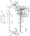
- the support element 26 is designed as an endless support belt 146 connected upstream of the opening device 24, which at its effective end by a deflection wheel 46 'coaxial deflection roller 148 is deflected.
- the support belt 146 is driven at a speed v3, which is at least the same size, but preferably greater than the conveying speed v of the conveying device 10.
- the printed products 20 transported by the fold 22 by the conveying clamps 14 with an approximately horizontal conveying direction F lie forward with them bent end region 28 flat on the support band 146.
- the longer product part 32 with the edge section 34, which protrudes over the shorter product part 36, is on top.
- the first traction element 42 with the first grippers 38 is deflected around the deflection wheel 46, which, seen in the conveying direction F, is connected upstream of the deflection wheel 46 'for the second traction element 44 and the deflection roller 148.
- the distance B between the first grippers 38 is the same as the distance A between the transport clamps 14 or less.
- the active strand 42 'of the first pulling element 42 runs from the deflection wheel 46 to the deflection wheel 48 and thus overlaps the active strand 44' of the second pulling element 44, which extends from the deflection wheel 46 'to the deflection wheel 48' which is coaxial with the deflection wheel 48 '.
- the distance C between the second grippers 40 is greater than the distance B between the first grippers 38.
- the rotational speed v2 is correspondingly greater of the second pulling element 44 with respect to the rotational speed v1 of the first grippers 38.
- These different speeds v1, v2 are generated in that the driven deflecting wheel 50 for the first pulling element 42 is correspondingly smaller in diameter than the deflecting wheel 50 'of the second pulling element 44.
- the ratio of the speeds v1 to v2 behaves the same as the ratio of the distances B to C.
- the grippers 38, 40 are of exactly the same design as described above and shown in FIGS. 6-13. Only the gripper jaw 68 of the first gripper 38 and gripper jaw 92 of the second gripper 40 are directed against the conveying direction F. Otherwise, the structure of the opening device 24 corresponds to the training forms already described above. Exactly the same reference numerals are used for functionally identical parts and they are only entered in FIGS. 27 and 28 to the extent necessary for the following explanation of the mode of operation.
- a second gripper 40 which just before the end edge 32 'of the Product part 32 intersects the path of movement of the radially outer end of the second gripper 40, reaches the area of the active run 44 'and is pivoted backwards in the counterclockwise direction in the direction of conveyance F as seen by the dash-dotted pivot link 110 in order to open the edge section with its open gripper mouth 92 34 to embrace.
- the clamping pin 90 When running off the opening link 104, the clamping pin 90 is raised and the edge section 34 is clamped between the latter and the gripper jaw 86.
- the clamping tongue 64 When the first gripper 38 runs from the corresponding opening link 78, the clamping tongue 64 is moved into the closed position and clamps the product part 36 between it and the clamping jaw 66, which was pushed into the open gripper mouth 68 by the support band 146.
- the product part 32 on top is now moved away from the product part 36 on the bottom in the direction of conveyance F and is thereby moved into a more extended position, as can be seen in particular in FIG. 28.
- the product part 36 maintains its bend or is bent even more if the speed v1 of the first grippers 38 is lower than the conveying speed v of the conveyor device 10.
- the second gripper 40 With the opening gate 104 'or 78', the second gripper 40 becomes first and later in time the first gripper 38 is opened in the region of the deflection wheels 48, 48 '.
- the further processing of the printed products can be carried out in exactly the same way as is shown in FIGS. 1-3.
- the opening device 24 can be used as they are 27 and 28, printed products 20 are also processed, which are fed to the opening device 24 with the leading end region 28 and the lower edge section 34.
- the lifting off of the two product parts 32, 36 then takes place in an analogous manner, as shown in FIGS. 19-23 and described further above.
- the clamping tongue 64 and the bending member 142 form separating means in order to lift the two product parts 32, 36 from each other transversely to the conveying direction F.
- the two product parts 32, 36 can thereby each be securely gripped by the corresponding grippers 38, 40.
- the deflection wheel 46 'for the second pulling element 44 with the second grippers 40 seen in the conveying direction F, is connected upstream of the deflection wheel 46 for the first pulling element 42 with the first grippers 38.
- the active dreams 42 ′ and 44 ′ overlap.
- the traction elements 42, 44 are driven in the same way as described above via deflection wheels 50, 50 '(compare FIGS. 25, 26), which are no longer shown in FIG. 29.
- the speed v1 of the first grippers 38 and the distance B between these grippers 38 are correspondingly greater than the speed v2 of the second grippers 40 and the distance C between these grippers 40. Furthermore, the speed v2 is at least as great as, but preferably greater than the conveying speed v of the transport clamps 14 of the conveying device 10; the distances are a matter of course A and C matched accordingly.
- the support plate 120 has a step 120 'falling in the conveying direction F in the deflection wheel 46. Up to this step 120 ', the support-active surface of the support plate 120 is above the clamping pins 90 of the opened second grippers 40, but of course below the gripper jaw 86. In the direction of conveyance F following the step 120', the support-active surface of the support plate 120 is aligned with the clamping jaw 66 the first gripper 38. In this embodiment too, the movement path of the gripper mouth 92 runs above the first grippers 38.
- the structure of the grippers 38, 40 is exactly the same as described above and shown in FIGS. 6 to 13; however, the second grippers 40, like the first grippers 38, are fixed, i.e. are not pivotally arranged on the tension members 42, 44.
- the opening scenes 78, 78 ', 104, 104' described above are not shown in FIG. 29; their position can be seen from the following functional description of the device according to FIG.
- the printed products 20 which are held approximately vertically hanging by their clamps 22 from transport clips 14 are transported with their end region 28 resting on the support plate 120 at the conveying speed v.
- the longer product part 32 with the edge section 34 is trailing and overhead with respect to the shorter product part 36.
- the product part 36 located below is clamped and moved away from the other product part 32 in the conveying direction F.
- the grippers 38, 40 are then opened one after the other, so that they release the product parts 32, 36 which are lifted from one another.
- the structure of the opening device 24 shown in FIG. 30 is extremely similar to that of the opening device according to FIG. 29. In the following, only the differences are referred to, insofar as this is necessary for understanding.
- the deflection wheels 46, 46 ', 48, 48', 50, 50 ' are arranged exactly the same and the traction members 42, 44 are guided in the same way as in FIG.
- the speed v1 of the second grippers 40 is approximately the same large as, but preferably lower than the conveying speed v.
- the speed v1 of the first gripper 38 is lower than the speed v2.
- the distance A between the transport clamps 14 is the same as or greater than the distance C between the second grippers 40, and the distance B between the first grippers 38 is smaller than the distance C.
- the support belt 146 is driven at a speed in the conveying direction F which is at least the same size, preferably greater than the conveying speed v, in order to feed the printed products 20 lying thereon with their end region 28 with the leading edge section 34 to the second grippers 40.
- the support belt 146 which runs in a gap in the support plate 120 and projects with its active upper run over the support plate 120, is guided around a roller, not shown in FIG. 30, which is supported coaxially with the deflection wheel 46, so that it is in front of the deflection wheel 46 '' is supportive and supportive until the deflection wheel 46.
- the traction elements 42, 44 are synchronized in such a way that in one area, beginning with the deflection wheel 46 until after the falling step 120 ′ in the support plate 120, the first gripper 38 in each case leads the corresponding second gripper 40 and then before reaching the deflection wheels 48, 48 'The second gripper 40 overtakes the first gripper 38.
- the printed products 20 are conveyed by the transport clamps 14 hanging in the fold 20 approximately in the vertical direction.
- the longer product part 32 is compared to the shorter one Product part 36 each leading, so that the end portion 28 is leading and the edge portion 34 is overhead due to the support band 146.
- a second gripper 40 which is opened by means of the opening backdrop, not shown, swings in between two printed products 20 in each case.
- the edge section 34 runs into the open gripper jaw 92, so that when the gripper 40 closes on the deflection wheel 46, the edge section 34, which is gripped by the clamping pin 90, is raised and clamped in the gripper jaw 92 .
- the shorter product part 36 lying below falls further away from the upper product part 32 with its section adjoining the leading end edge 36' and reaches the mouth 68 of the first gripper 38, for example when this is overtaken by the corresponding second gripper 40 .
- the clamping pin 90 and the step 120 ′ in the support plate 120 form the separating means in order to lift the adjacent product parts 32, 36 from one another transversely to the conveying direction.
- the grippers can have a different design. It is also conceivable not to drive them around, but to move them back and forth.
- the traction elements 42, 44 can also be driven individually. This enables simple synchronization and adaptation to different formats of the print products to be opened.
- the printed products can be opened on the left, in the middle, or on the right. It is also conceivable to arrange two identical opening devices 24 next to one another, so that the printed products are opened simultaneously in two areas.
Landscapes
- Engineering & Computer Science (AREA)
- Mechanical Engineering (AREA)
- Textile Engineering (AREA)
- Discharge By Other Means (AREA)
- Feeding Of Articles By Means Other Than Belts Or Rollers (AREA)
- Auxiliary Devices For And Details Of Packaging Control (AREA)
- Packages (AREA)
- Sheets, Magazines, And Separation Thereof (AREA)
- Closing Of Containers (AREA)
Applications Claiming Priority (2)
| Application Number | Priority Date | Filing Date | Title |
|---|---|---|---|
| CH111692 | 1992-04-06 | ||
| CH1116/92 | 1992-04-06 |
Publications (2)
| Publication Number | Publication Date |
|---|---|
| EP0564812A1 true EP0564812A1 (fr) | 1993-10-13 |
| EP0564812B1 EP0564812B1 (fr) | 1997-05-28 |
Family
ID=4202864
Family Applications (1)
| Application Number | Title | Priority Date | Filing Date |
|---|---|---|---|
| EP93103235A Expired - Lifetime EP0564812B1 (fr) | 1992-04-06 | 1993-03-01 | Procédé et dispositif pour ouvrir des produits d'imprimerie pliés |
Country Status (7)
| Country | Link |
|---|---|
| US (2) | US5354043A (fr) |
| EP (1) | EP0564812B1 (fr) |
| JP (1) | JP2700287B2 (fr) |
| AT (1) | ATE153628T1 (fr) |
| CA (1) | CA2093400C (fr) |
| DE (1) | DE59306556D1 (fr) |
| ES (1) | ES2101889T3 (fr) |
Cited By (1)
| Publication number | Priority date | Publication date | Assignee | Title |
|---|---|---|---|---|
| EP0709326A1 (fr) | 1994-10-28 | 1996-05-01 | Ferag AG | Méthode et dispositif pour marquer des produits imprimés et pliés sur une page intérieure |
Families Citing this family (15)
| Publication number | Priority date | Publication date | Assignee | Title |
|---|---|---|---|---|
| DE59302441D1 (de) * | 1992-12-04 | 1996-06-05 | Ferag Ag | Verfahren und Vorrichtung zum Oeffnen von gefalteten Druckereiprodukten |
| DE59405887D1 (de) * | 1993-10-08 | 1998-06-10 | Ferag Ag | Vorrichtung zum Oeffnen und Weitertransportieren von Druckereiprodukten |
| EP0659586B1 (fr) * | 1993-12-21 | 1998-05-06 | Grapha-Holding Ag | Procédé pour délivrer un ensemble de feuilles imprimées avec des encarts |
| EP0718225A3 (fr) * | 1994-12-22 | 1996-12-11 | Grapha Holding Ag | Dispositif pour alimenter une section d'assemblage d'une assembleuse et brocheuse combinée |
| DE59503157D1 (de) * | 1995-01-13 | 1998-09-17 | Ferag Ag | Vorrichtung zum Öffnen von Druckereiprodukten und Einrichtung zum Verarbeiten von Druckereiprodukten |
| US5655760A (en) * | 1996-05-14 | 1997-08-12 | Heidelberg Finishing Systems Inc. | Collator with air assistance |
| EP0831045B1 (fr) * | 1996-09-06 | 2001-11-28 | Ferag AG | Méthode et dipositif pour l'ouverture de produits flexibles et plats |
| US5758871A (en) * | 1996-09-25 | 1998-06-02 | Heidelberg Finishing Systems, Inc. | Signature collating apparatus |
| ATE292079T1 (de) * | 2000-03-03 | 2005-04-15 | Ferag Ag | Vorrichtung zum verarbeiten von zwei- und mehrteiligen, flächigen, flexiblen gegenständen |
| EP1351875B1 (fr) * | 2001-01-19 | 2006-05-10 | Ferag AG | Dispositif de reception de produits d'imprimerie |
| DE502004007043D1 (de) * | 2003-12-22 | 2008-06-19 | Ferag Ag | Verfahren und Vorrichtung zur Stabilisierung und Positionierung von flächigen Gegenständen |
| WO2009015503A1 (fr) * | 2007-07-30 | 2009-02-05 | Ferag Ag | Système d'assemblage de groupes d'objets plats |
| US8398064B2 (en) * | 2008-05-26 | 2013-03-19 | Ferag Ag | Apparatus for, and method of, inserting flat objects into a folded printed product |
| CH701468A1 (de) * | 2009-07-13 | 2011-01-14 | Ferag Ag | Verfahren und Vorrichtung zum Öffnen von Druckereiprodukten. |
| CH703248A1 (de) | 2010-05-31 | 2011-12-15 | Ferag Ag | Vorrichtung und verfahren zum öffnen von druckereiprodukten. |
Citations (8)
| Publication number | Priority date | Publication date | Assignee | Title |
|---|---|---|---|---|
| US2817513A (en) * | 1954-06-29 | 1957-12-24 | Kenneth T Moser | Sheet separating means for collating machine |
| DE1024530B (de) * | 1954-11-18 | 1958-02-20 | Rudolf Hepp | Verfahren und Vorrichtung zum voneinander Abheben gefalzter Papierlagen mit vorstehendem Rand zwecks Ineinandersteckens der Papierlagen |
| GB1095733A (en) * | 1964-12-14 | 1967-12-20 | Leipziger Buchbindereimaschine | Method of and apparatus for opening folded sheets |
| FR1530715A (fr) * | 1965-11-24 | 1968-06-28 | Ferag Ag | Installation pour ouvrir un produit comprenant plusieurs feuilles de papier et y introduire un supplément |
| DE1817030A1 (de) * | 1968-02-02 | 1969-08-07 | Ferag Ag | Verfahren zum OEffnen von mehrblaettrigen,gefalteten Druckereierzeugnissen,insbesondere Zeitungen sowie eine Einrichtung zur Durchfuehrung des Verfahrens |
| GB2066790A (en) * | 1980-01-08 | 1981-07-15 | Ferag Ag | Method and apparatus for opening folded bound or stitched multi-sheet products especially printed products |
| EP0095603A1 (fr) * | 1982-06-01 | 1983-12-07 | Ferag AG | Dispositif d'assemblage de feuilles pliées d'imprimerie |
| EP0208081A1 (fr) * | 1985-07-01 | 1987-01-14 | Ferag AG | Procédé et dispositif d'ouverture pour imprimés pliés de manière excentrée |
Family Cites Families (8)
| Publication number | Priority date | Publication date | Assignee | Title |
|---|---|---|---|---|
| AT296932B (de) * | 1965-11-24 | 1972-03-10 | Ferag Ag | Vorrichtung zum Einführen von Beilagen in gefaltete Druckereierzeugnisse |
| CH667620A5 (de) * | 1985-07-01 | 1988-10-31 | Ferag Ag | Verfahren und vorrichtung zum sammeln von gefalzten druckbogen. |
| CH667859A5 (en) * | 1985-07-19 | 1988-11-15 | Ferag Ag | Folded printed item opening mechanism - has holders securing items at position along fold to prevent turning |
| EP0352421A3 (fr) * | 1988-07-26 | 1990-08-29 | R. R. Donnelley & Sons Company | Dispositif et procédé d'impression individuelle de cahiers pendant la sortie sur un transporteur d'une ligne de reliure |
| ES2065105T3 (es) * | 1991-06-10 | 1995-02-01 | Ferag Ag | Procedimiento y dispositivo para la apertura y el deposito sobre un soporte en forma de silla de productos de imprenta plegados. |
| EP0518064B1 (fr) * | 1991-06-10 | 1995-11-15 | Ferag AG | Procédé et appareil pour la manutention de produits imprimés |
| DE59201323D1 (de) * | 1991-07-11 | 1995-03-16 | Ferag Ag | Verfahren und Vorrichtung zum Oeffnen von flexiblen, aussermittig gefalteten Erzeugnissen. |
| US5277413A (en) * | 1991-12-19 | 1994-01-11 | Grapha-Holding Ag | Rotary signature gathering apparatus with sheet stop |
-
1993
- 1993-03-01 DE DE59306556T patent/DE59306556D1/de not_active Expired - Lifetime
- 1993-03-01 AT AT93103235T patent/ATE153628T1/de not_active IP Right Cessation
- 1993-03-01 ES ES93103235T patent/ES2101889T3/es not_active Expired - Lifetime
- 1993-03-01 EP EP93103235A patent/EP0564812B1/fr not_active Expired - Lifetime
- 1993-03-24 JP JP5089358A patent/JP2700287B2/ja not_active Expired - Lifetime
- 1993-04-05 US US08/044,782 patent/US5354043A/en not_active Expired - Lifetime
- 1993-04-05 CA CA002093400A patent/CA2093400C/fr not_active Expired - Fee Related
-
1994
- 1994-10-07 US US08/319,942 patent/US5474286A/en not_active Expired - Lifetime
Patent Citations (8)
| Publication number | Priority date | Publication date | Assignee | Title |
|---|---|---|---|---|
| US2817513A (en) * | 1954-06-29 | 1957-12-24 | Kenneth T Moser | Sheet separating means for collating machine |
| DE1024530B (de) * | 1954-11-18 | 1958-02-20 | Rudolf Hepp | Verfahren und Vorrichtung zum voneinander Abheben gefalzter Papierlagen mit vorstehendem Rand zwecks Ineinandersteckens der Papierlagen |
| GB1095733A (en) * | 1964-12-14 | 1967-12-20 | Leipziger Buchbindereimaschine | Method of and apparatus for opening folded sheets |
| FR1530715A (fr) * | 1965-11-24 | 1968-06-28 | Ferag Ag | Installation pour ouvrir un produit comprenant plusieurs feuilles de papier et y introduire un supplément |
| DE1817030A1 (de) * | 1968-02-02 | 1969-08-07 | Ferag Ag | Verfahren zum OEffnen von mehrblaettrigen,gefalteten Druckereierzeugnissen,insbesondere Zeitungen sowie eine Einrichtung zur Durchfuehrung des Verfahrens |
| GB2066790A (en) * | 1980-01-08 | 1981-07-15 | Ferag Ag | Method and apparatus for opening folded bound or stitched multi-sheet products especially printed products |
| EP0095603A1 (fr) * | 1982-06-01 | 1983-12-07 | Ferag AG | Dispositif d'assemblage de feuilles pliées d'imprimerie |
| EP0208081A1 (fr) * | 1985-07-01 | 1987-01-14 | Ferag AG | Procédé et dispositif d'ouverture pour imprimés pliés de manière excentrée |
Cited By (2)
| Publication number | Priority date | Publication date | Assignee | Title |
|---|---|---|---|---|
| EP0709326A1 (fr) | 1994-10-28 | 1996-05-01 | Ferag AG | Méthode et dispositif pour marquer des produits imprimés et pliés sur une page intérieure |
| US5596932A (en) * | 1994-10-28 | 1997-01-28 | Ferag Ag | Process and apparatus for the typographical labeling of folded printed products on an inner side |
Also Published As
| Publication number | Publication date |
|---|---|
| US5474286A (en) | 1995-12-12 |
| CA2093400C (fr) | 1999-01-19 |
| EP0564812B1 (fr) | 1997-05-28 |
| US5354043A (en) | 1994-10-11 |
| JP2700287B2 (ja) | 1998-01-19 |
| JPH069148A (ja) | 1994-01-18 |
| DE59306556D1 (de) | 1997-07-03 |
| ATE153628T1 (de) | 1997-06-15 |
| ES2101889T3 (es) | 1997-07-16 |
| CA2093400A1 (fr) | 1993-10-07 |
Similar Documents
| Publication | Publication Date | Title |
|---|---|---|
| EP0346578B1 (fr) | Dispositif pour assembler, collationner et insérer des produits imprimés | |
| EP0564812B1 (fr) | Procédé et dispositif pour ouvrir des produits d'imprimerie pliés | |
| EP0551601B1 (fr) | Dispositif et procédé pour l'alimentation spécialement de produits imprimés pliés vers un autre poste de travail | |
| EP0208081B1 (fr) | Procédé et dispositif d'ouverture pour imprimés pliés de manière excentrée | |
| EP0330868B1 (fr) | Procédé et dispositif d'évacuation de produits imprimés, qui sont amenés en formation en écailles | |
| EP0518063B1 (fr) | Procédé et dispositif pour ouvrir et pour déposer sur un support en forme de selle des produits pliés d'imprimerie | |
| EP0305671B1 (fr) | Convoyeur pour des imprimés et application du convoyeur | |
| EP0522319B1 (fr) | Procédé et dispositif pour ouvrir des articles flexible pliés hors du centre | |
| EP0600216B1 (fr) | Procédé et dispositif pour ouvrir des produits d'imprimerie pliés | |
| DE3306815C2 (de) | Vorrichtung zum transportieren von in einer schuppenformation anfallenden flaechigen erzeugnissen, insbesondere druckprodukten | |
| AT396908B (de) | Vorrichtung zum verarbeiten von druckprodukten | |
| DE2058606A1 (de) | Verfahren und Vorrichtung zum seitlichen Ausrichten von Blaettern,insbesondere bei einer Druckpresse | |
| EP0300171B1 (fr) | Dispositif de transport pour produits plats, en particulier des produits imprimés | |
| EP0218804B1 (fr) | Dispositif pour reprendre et transférer des feuilles pliées d'un dispositif de transport | |
| EP0647582A1 (fr) | Dispositif pour ouvrir et transporter des produits imprimés | |
| DE19833851A1 (de) | Verfahren und Vorrichtung zur Erstellung eines gedrehten Produktstromes mit einem Eckengreifer | |
| EP0518064B1 (fr) | Procédé et appareil pour la manutention de produits imprimés | |
| CH683913A5 (de) | Transporteur für kontinuierlich anfallende Flächengebilde, insbesondere Druckereiprodukte. | |
| EP0300170B1 (fr) | Procédé et dispositif de séparation de produits se chevauchant, en particulier de produits imprimés | |
| EP1072546B1 (fr) | Convoyeur pour assembler et traiter des produits imprimés | |
| DE1561141B2 (de) | Vorrichtung zum einfuehren von beilagen in gefaltete druckerzeugnisse | |
| EP1411011B1 (fr) | Dispositif pour le transfert de produits à un dispositif de transport | |
| EP0699611B1 (fr) | Dispositif de transport pour l'alimentation des produits imprimés plats à une machine de traitement | |
| CH690576A5 (de) | Vorrichtung zum Verarbeiten von Druckereiprodukten. | |
| EP2418164B1 (fr) | Procédé et dispositif d'assemblage de produits plats avec d'autres produits plats et dispositif de transport de produits plats, notamment de produits d'imprimerie |
Legal Events
| Date | Code | Title | Description |
|---|---|---|---|
| PUAI | Public reference made under article 153(3) epc to a published international application that has entered the european phase |
Free format text: ORIGINAL CODE: 0009012 |
|
| 17P | Request for examination filed |
Effective date: 19930713 |
|
| AK | Designated contracting states |
Kind code of ref document: A1 Designated state(s): AT CH DE ES FR GB IT LI NL SE |
|
| GRAG | Despatch of communication of intention to grant |
Free format text: ORIGINAL CODE: EPIDOS AGRA |
|
| GRAH | Despatch of communication of intention to grant a patent |
Free format text: ORIGINAL CODE: EPIDOS IGRA |
|
| 17Q | First examination report despatched |
Effective date: 19960808 |
|
| GRAH | Despatch of communication of intention to grant a patent |
Free format text: ORIGINAL CODE: EPIDOS IGRA |
|
| GRAA | (expected) grant |
Free format text: ORIGINAL CODE: 0009210 |
|
| ITF | It: translation for a ep patent filed | ||
| AK | Designated contracting states |
Kind code of ref document: B1 Designated state(s): AT CH DE ES FR GB IT LI NL SE |
|
| REF | Corresponds to: |
Ref document number: 153628 Country of ref document: AT Date of ref document: 19970615 Kind code of ref document: T |
|
| REG | Reference to a national code |
Ref country code: CH Ref legal event code: NV Representative=s name: PATENTANWAELTE SCHAAD, BALASS, MENZL & PARTNER AG Ref country code: CH Ref legal event code: EP |
|
| GBT | Gb: translation of ep patent filed (gb section 77(6)(a)/1977) |
Effective date: 19970528 |
|
| REF | Corresponds to: |
Ref document number: 59306556 Country of ref document: DE Date of ref document: 19970703 |
|
| REG | Reference to a national code |
Ref country code: ES Ref legal event code: FG2A Ref document number: 2101889 Country of ref document: ES Kind code of ref document: T3 |
|
| ET | Fr: translation filed | ||
| PLBE | No opposition filed within time limit |
Free format text: ORIGINAL CODE: 0009261 |
|
| STAA | Information on the status of an ep patent application or granted ep patent |
Free format text: STATUS: NO OPPOSITION FILED WITHIN TIME LIMIT |
|
| 26N | No opposition filed | ||
| PGFP | Annual fee paid to national office [announced via postgrant information from national office to epo] |
Ref country code: NL Payment date: 20000223 Year of fee payment: 8 |
|
| PGFP | Annual fee paid to national office [announced via postgrant information from national office to epo] |
Ref country code: ES Payment date: 20000321 Year of fee payment: 8 |
|
| PGFP | Annual fee paid to national office [announced via postgrant information from national office to epo] |
Ref country code: AT Payment date: 20010226 Year of fee payment: 9 |
|
| PG25 | Lapsed in a contracting state [announced via postgrant information from national office to epo] |
Ref country code: ES Free format text: LAPSE BECAUSE OF NON-PAYMENT OF DUE FEES Effective date: 20010302 |
|
| PGFP | Annual fee paid to national office [announced via postgrant information from national office to epo] |
Ref country code: FR Payment date: 20010313 Year of fee payment: 9 |
|
| PG25 | Lapsed in a contracting state [announced via postgrant information from national office to epo] |
Ref country code: NL Free format text: LAPSE BECAUSE OF NON-PAYMENT OF DUE FEES Effective date: 20011001 |
|
| NLV4 | Nl: lapsed or anulled due to non-payment of the annual fee |
Effective date: 20011001 |
|
| REG | Reference to a national code |
Ref country code: GB Ref legal event code: IF02 |
|
| PG25 | Lapsed in a contracting state [announced via postgrant information from national office to epo] |
Ref country code: AT Free format text: LAPSE BECAUSE OF NON-PAYMENT OF DUE FEES Effective date: 20020301 |
|
| PG25 | Lapsed in a contracting state [announced via postgrant information from national office to epo] |
Ref country code: FR Free format text: LAPSE BECAUSE OF NON-PAYMENT OF DUE FEES Effective date: 20021129 |
|
| REG | Reference to a national code |
Ref country code: FR Ref legal event code: ST |
|
| REG | Reference to a national code |
Ref country code: ES Ref legal event code: FD2A Effective date: 20030203 |
|
| REG | Reference to a national code |
Ref country code: CH Ref legal event code: PFA Owner name: FERAG AG Free format text: FERAG AG##CH-8340 HINWIL (CH) -TRANSFER TO- FERAG AG#PATENTABTEILUNG Z. H. MARKUS FELIX ZUERICHSTRASSE 74#8340 HINWIL (CH) |
|
| PG25 | Lapsed in a contracting state [announced via postgrant information from national office to epo] |
Ref country code: IT Free format text: LAPSE BECAUSE OF NON-PAYMENT OF DUE FEES Effective date: 20050301 |
|
| PGFP | Annual fee paid to national office [announced via postgrant information from national office to epo] |
Ref country code: GB Payment date: 20090325 Year of fee payment: 17 |
|
| GBPC | Gb: european patent ceased through non-payment of renewal fee |
Effective date: 20100301 |
|
| PGFP | Annual fee paid to national office [announced via postgrant information from national office to epo] |
Ref country code: SE Payment date: 20100312 Year of fee payment: 18 |
|
| PG25 | Lapsed in a contracting state [announced via postgrant information from national office to epo] |
Ref country code: GB Free format text: LAPSE BECAUSE OF NON-PAYMENT OF DUE FEES Effective date: 20100301 |
|
| REG | Reference to a national code |
Ref country code: SE Ref legal event code: EUG |
|
| PGFP | Annual fee paid to national office [announced via postgrant information from national office to epo] |
Ref country code: DE Payment date: 20120323 Year of fee payment: 20 |
|
| PGFP | Annual fee paid to national office [announced via postgrant information from national office to epo] |
Ref country code: CH Payment date: 20120606 Year of fee payment: 20 |
|
| REG | Reference to a national code |
Ref country code: DE Ref legal event code: R071 Ref document number: 59306556 Country of ref document: DE |
|
| REG | Reference to a national code |
Ref country code: DE Ref legal event code: R071 Ref document number: 59306556 Country of ref document: DE |
|
| REG | Reference to a national code |
Ref country code: CH Ref legal event code: PL |
|
| PG25 | Lapsed in a contracting state [announced via postgrant information from national office to epo] |
Ref country code: SE Free format text: LAPSE BECAUSE OF NON-PAYMENT OF DUE FEES Effective date: 20110302 Ref country code: DE Free format text: LAPSE BECAUSE OF EXPIRATION OF PROTECTION Effective date: 20130302 |