EP0564901B1 - Dispositif d'avance pour tÔle - Google Patents
Dispositif d'avance pour tÔle Download PDFInfo
- Publication number
- EP0564901B1 EP0564901B1 EP93104838A EP93104838A EP0564901B1 EP 0564901 B1 EP0564901 B1 EP 0564901B1 EP 93104838 A EP93104838 A EP 93104838A EP 93104838 A EP93104838 A EP 93104838A EP 0564901 B1 EP0564901 B1 EP 0564901B1
- Authority
- EP
- European Patent Office
- Prior art keywords
- feeding device
- speed
- arrangement
- driver
- drive
- Prior art date
- Legal status (The legal status is an assumption and is not a legal conclusion. Google has not performed a legal analysis and makes no representation as to the accuracy of the status listed.)
- Expired - Lifetime
Links
Images



Classifications
-
- B—PERFORMING OPERATIONS; TRANSPORTING
- B65—CONVEYING; PACKING; STORING; HANDLING THIN OR FILAMENTARY MATERIAL
- B65G—TRANSPORT OR STORAGE DEVICES, e.g. CONVEYORS FOR LOADING OR TIPPING, SHOP CONVEYOR SYSTEMS OR PNEUMATIC TUBE CONVEYORS
- B65G17/00—Conveyors having an endless traction element, e.g. a chain, transmitting movement to a continuous or substantially-continuous load-carrying surface or to a series of individual load-carriers; Endless-chain conveyors in which the chains form the load-carrying surface
- B65G17/26—Conveyors having an endless traction element, e.g. a chain, transmitting movement to a continuous or substantially-continuous load-carrying surface or to a series of individual load-carriers; Endless-chain conveyors in which the chains form the load-carrying surface comprising a series of co-operating units, e.g. interconnected by pivots
-
- B—PERFORMING OPERATIONS; TRANSPORTING
- B65—CONVEYING; PACKING; STORING; HANDLING THIN OR FILAMENTARY MATERIAL
- B65H—HANDLING THIN OR FILAMENTARY MATERIAL, e.g. SHEETS, WEBS, CABLES
- B65H9/00—Registering, e.g. orientating, articles; Devices therefor
- B65H9/14—Retarding or controlling the forward movement of articles as they approach stops
-
- B—PERFORMING OPERATIONS; TRANSPORTING
- B23—MACHINE TOOLS; METAL-WORKING NOT OTHERWISE PROVIDED FOR
- B23D—PLANING; SLOTTING; SHEARING; BROACHING; SAWING; FILING; SCRAPING; LIKE OPERATIONS FOR WORKING METAL BY REMOVING MATERIAL, NOT OTHERWISE PROVIDED FOR
- B23D33/00—Accessories for shearing machines or shearing devices
- B23D33/02—Arrangements for holding, guiding, and/or feeding work during the operation
-
- B—PERFORMING OPERATIONS; TRANSPORTING
- B23—MACHINE TOOLS; METAL-WORKING NOT OTHERWISE PROVIDED FOR
- B23Q—DETAILS, COMPONENTS, OR ACCESSORIES FOR MACHINE TOOLS, e.g. ARRANGEMENTS FOR COPYING OR CONTROLLING; MACHINE TOOLS IN GENERAL CHARACTERISED BY THE CONSTRUCTION OF PARTICULAR DETAILS OR COMPONENTS; COMBINATIONS OR ASSOCIATIONS OF METAL-WORKING MACHINES, NOT DIRECTED TO A PARTICULAR RESULT
- B23Q7/00—Arrangements for handling work specially combined with or arranged in, or specially adapted for use in connection with, machine tools, e.g. for conveying, loading, positioning, discharging, sorting
- B23Q7/007—Flying working devices
-
- B—PERFORMING OPERATIONS; TRANSPORTING
- B65—CONVEYING; PACKING; STORING; HANDLING THIN OR FILAMENTARY MATERIAL
- B65H—HANDLING THIN OR FILAMENTARY MATERIAL, e.g. SHEETS, WEBS, CABLES
- B65H2404/00—Parts for transporting or guiding the handled material
- B65H2404/20—Belts
- B65H2404/23—Belts with auxiliary handling means
- B65H2404/232—Blade, plate, finger
Definitions
- the invention relates to a feed device with a traction device that rotates at a constant speed and is provided with driver pawls for transporting panels into a work station with a constant throughput speed, into which the panels enter at an initial speed that is at least as great as the rotational speed of the traction means or the entraining pawls .
- the traction means of the feed device can in particular be designed as a chain. Sheet metal or sheet metal strips are preferred, but also blanks can be used.
- a typical work station into which sheets enter is a round or roller knife shear in which the throughput speed is constant and corresponds to the initial speed. The initial speed at which the sheets are drawn into the work station must under no circumstances be lower than the feed rate, as otherwise the sheets will be compressed. In practice, the initial speed of the work station is chosen to be somewhat greater than that of the feed device.
- Roller knife scissors cut sheet metal, for example tinplate for sheet metal packaging, into strips in a first operation and then cut the strips into blanks in a second operation.
- Known feed devices both for metal sheets and for sheet metal blanks have a chain feed, the rotational speed of which is lower than the circumferential or Feed speed of the roller knives.
- the feed device according to the prior art is followed by a pawl feed with linearly reciprocating ratchet rails.
- the throughput of the roller knife shears is largely determined by the stroke, the function and the stroke frequency of the oscillating ratchet slide drive.
- Does the slide drive e.g. seven strokes / board, 280 strokes / min with a stroke of approx. 100 mm must be achieved for an output of 40 boards / min.
- enormous accelerations and inertial forces occur. Even the output mentioned can only be achieved with great effort in terms of manufacturing accuracy and with light materials.
- the slide drive is subject to great wear due to the high inertial forces and generates high noise immissions.
- the invention has for its object to improve a feed device of the type mentioned in such a way that, with the same wear or the same noise immission, a higher output (plates / min) or with the same output, a lower wear and a lower noise immission can be achieved.
- this object is first achieved in that a further feed device is arranged in the area of the feed device, which has a rotating traction means driven by a drive arrangement with a driver arrangement arranged transversely to the feed direction.
- the driver arrangement reaches at least one point in the area of the upper run of the traction means Speed that is greater than or equal to the rotational speed of the first feed device and at this or another time a speed that is less than or equal to the initial speed of the drive station.
- the object is additionally achieved on the one hand in that the rotating traction means of the further feed can be moved by the drive arrangement with a periodically variable rotational speed, the minimum of which is less than or equal to the rotational speed of the first feed device and the maximum of which is greater than the rotational speed of the first feed device and less than or equal to Initial speed is in the work station, and that the driver arrangement is at least at the end of the acceleration phase in the area of the upper run.
- the driver arrangement of the further feed device overtakes the drivers of the first feed device. In doing so, they grasp the rear edge of the board and move it forward from the driver pawl of the first feed device which was originally in engagement. As you accelerate further, you will approach the speed of the workstation, e.g. the (constant) rotational speed of the knife body of a roller knife shear. After the table has been taken over by the work station (the roller knife scissors), the speed of rotation of the further feed device decreases in the direction of a minimum speed, so that there is a distance between the table and the driver pawls.
- the object underlying the invention is additionally achieved in that the driver arrangement has driver pawls which, prior to the transition, result from the linear movement of the upper run assume a position below the transport plane of the metal sheets in the deflection movement in the direction of the lower strand, at least up to an initial region of the deflection movement.
- the driver pawls of a traction device advance necessarily extend in height above the traction device for feeding a panel.
- the upper edge of the driving pawl is moved faster than the speed of rotation of the traction device in relation to the difference in height.
- the board pushed by the feed device thus experiences an unwanted acceleration in the transition area, which can result in compression and in extreme cases even damage to the board.
- the advantage of a feed device according to the second solution is that the further feed device can also be operated at a constant rotational speed if the rotational speed is equal to the initial speed - generally: the (constant) speed - of the work station.
- a periodically variable rotational speed of the driver arrangement of the further feed device is preferably achieved by a universal joint via which the further feed device is connected to the drive. While the pulsating deviation from the exact concentricity of a universal joint is generally tolerated rather annoying, the effect of the universal joint is consciously used in the present case to achieve a desired effect.
- the pulsation is compensated for in the Z-shaped arrangement of an articulated shaft, the articulated axes or articulated forks of which lie in a common plane, the pulsation is increased if a second universal joint is provided between the axis of the further feed and the shaft of the drive Axis of the further feed, the cardan shaft arranged between the universal joints and the axis of the drive have a Z-shaped arrangement, and the universal joint axes of the cardan shaft or their joint forks are rotated by 90 ° relative to one another.
- the driver pawls of the further feed device can assume a position located below the transport plane of the metal sheets
- the driver pawl is mounted in a pawl holder which is pivotally mounted about a front, horizontal axis, as seen in the feed direction, on the rotating traction device and in the direction of the center of the Traction means acted upon by a spring preload.
- the pawl holder is loaded against a fixed guideway which in the area of the upper run is parallel to the feed plane and at a distance from the feed plane before the transition to the deflection to the lower run.
- the feed arrangement according to FIG. 1 has a first and a second feed device 1 or 2, the areas of which - seen in the feed direction V - overlap.
- a pair of roller knife shears 3 are arranged at a distance from the second feed device 2.
- the first feed device 1 has two chains 4 arranged at a lateral distance from one another, each of which rotates around a front and a rear sprocket 5, 6.
- the front and rear sprockets 5, 6 are each attached to a shaft 7 and 8, respectively.
- the front shaft 7 is connected in a known manner to a drive (not shown) which gives the chain 4 a constant, adjustable speed.
- the chains 4 each have one or more pawls 9, each of which is aligned with the corresponding pawl of the other chain perpendicular to the feed direction V.
- the second feed device 2 has two toothed belts 11 arranged at a lateral distance from one another, each deflected by a front and a rear toothed pulley 13 or 14, each with a driver pawl 12.
- the toothed disks 13 and 14 are attached in pairs on common shafts 15, 16.
- the rear shaft 16 is arranged between the shafts 7, 8 of the first feed device 1 and the front shaft 15 between the first feed device 1 and the pair of roller knife shafts 3.
- the feed device 2 is set up such that the two catches 12 are parallel to the shafts of the roller knife shears 3 swear.
- the upper run of the toothed belt 11 has the same height as the upper run of the chain 4. Seen in cross section (see FIG. 2), the two belts 11 are arranged on the outside next to the chains 4.
- the front shaft 15 is connected via a Z-shaped drive shaft arrangement 17 to a drive 18 with an adjustable constant speed n0 or constant angular speed ⁇ 0.
- the actual cardan shaft 20 designed as a spline-shaft connection is inclined relative to the shaft 15 and the shaft of the drive 18 at an angle ⁇ .
- the forks or the universal joint axes 21, 22 of the universal joint shaft 18 are - contrary to common practice - rotated by 90 ° relative to one another (while the left universal joint axis 21 is oriented transversely to the plane of the drawing in FIG.
- the universal joint axis 22 lies within the plane of the drawing).
- FIG 3 shows the rotational speed v12 proportional to the angular speed ⁇ 13 or ⁇ 15 of the driving pawl arrangement consisting of the two driving pawls 12 over one revolution of the shaft of the drive 18.
- the rotational speed is accelerated further from this point: the pawls 12 hurry ahead of the pawls 9 and thus take over the advance of the sheet metal plate T.
- the maximum speed v12 is such that it corresponds to the peripheral speed v3 of the roller knives 3 corresponds.
- the table is gripped by the pair of roller knives 3 and pulled off (FIG. 1).
- the toothed belts 11 are delayed again with the pawls 12, and the distance between the table pulled off by the pair of roller knives 3 and the pawls 12 increases noticeably.
- the pawls 12 are deflected around the toothed disks 13, reach their minimum v12min, are accelerated again, rush through the area of the lower run, are decelerated again and deflected around the toothed disks 14 and accelerated to the next period.
- the driver pawls 12 are accelerated in the region of the upper run from a speed below the rotational speed of the first feed device 1 to the peripheral speed of the pair of roller knives 3 and that the driver pawls 12 assume essentially the same feed position at the rotational speed of the first feed device how the pawls 9 and at the speed v3 have a distance from the pair of roller knives 3, which corresponds to a table length.
- a similarly uneven circulation speed can also be achieved by a rotary indexing gear or by an NC-controlled servo drive.
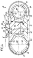
- the second feed device 30 has on each side a circumferential traction device designed as a toothed belt 31, to each of which a pawl arrangement 32 is attached.
- the endless toothed belts 31 are deflected at the front and rear on toothed pulley units 33, 34.
- One of the pulley units, e.g. 33, is driven - in synchronism with that on the other side - at a constant, adjustable speed, so that the pawl arrangement 32 is also moved at a constant rotational speed v32.
- the rotational speed v32 is greater than the rotational speed of the first feed device 1 and is just below that of the roller knife 3.
- the feed device 30 is set up in such a way that the two pawl arrangements 32 forming the driver arrangement are aligned parallel to the shafts of the pair of roller knives 3.
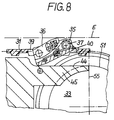
- the pawl arrangement 32 has a pawl holder 35 and a driver pawl 36.
- the pawl holder 35 which is U-shaped in cross section, is articulated at its front end on a bolt 37 which is held in two bolt holders 38 which are vulcanized onto each toothed belt 31.
- the toothed belt 31 has a recess 39 into which the pawl arrangement extends.
- the pawl holder 35 is pressed by a torsion spring 40 wound around the bolt 37 by the toothed belt 31 in the direction of the respective other strand or in the space within the toothed belt.
- shaped pieces 41, 42 are provided in the area of the upper run and the lower run - on each side of the feed device 2 - between the toothed disk units 33, 34, on which the underside of the pawl holder 35 can slide.
- the upper molding 41 has a slideway 43, which starts at the rear toothed disk unit 34 and runs parallel to the feed plane E.
- a lower-lying slideway 44 which is offset in comparison with the slideway 43 and which is arranged on a type of tongue 45 of the upper molding 41.
- the slideway 43 likewise forms the upper surface of a tongue 46 of the shaped piece 41.
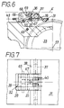
- the toothed disk units 33, 34 each have two outer toothed disks 47, 47 ', which are followed by shoulders 51 and a central recess 53 in the direction of the common central plane 49 (FIG. 5).
- the central recess 53 is so wide that the tongues 45 and 46 fit into it.
- the radius of the shoulders 51 corresponds to the distance of the slideway 44 from the axis 57 of the toothed disk unit 33 in the transition plane 55.
- the lower molding 42 has similar tongues 59, 60.
- the tongue 59 is again in the recess 53 of the toothed-disk unit 33, the tongue 60 in a corresponding recess of the toothed-disk unit 34.
- Both tongues 59, 60 have a common slideway 61.
- the slideway 61 In the transition plane 55, the slideway 61 has the same distance from the axis 57 as the slideway 44, corresponding to the radius of the shoulders 51. At its end, in the transition region 56, the slideway 61 has the same distance from the axis 58 of the toothed-disk unit 34 like the slideway 43.
- the shaped pieces 41, 42 are fastened to a machine frame (not shown) with the aid of screws 63, 64.
- the pawl holder 35 slides on the slideway 61, and the entire pawl arrangement 32 is continuously pressed outwards on the continuously increasing slideway 61.
- the pawl holder 35 rests on the lateral shoulders 52 of the toothed-disk unit 34 via the pins 65, and there is a smooth transition to the slideway 43.
- a fixed pawl protruding beyond a traction means has a higher speed in the region of the deflection, corresponding to its distance from the deflection axis, than the rotational speed of the traction means.
- this would either be accelerated in the transition region from the straight movement of the pawl into the circular path or - if the sheet was pulled off at a constant speed - would be compressed. This is prevented even in the case of a constant rotational speed in this embodiment in that the driver pawls 36 are retracted both in the feed direction V and in height by the “falling” or “descending” of the pawl holder 35.
- the pins 65 also serve to protect the pawl assembly 32 from “flying out” of the opening 39 in the event of strong centrifugal forces.
- the lateral pins 65 rest on the underside of the toothed belt 31, the tooth of the toothed belt being removed at the point in question.
- the driver pawls 36 can avoid an overtaking sheet metal plate, they are mounted around a bolt 66 of the pawl holder 35.
- the feed edge of the pawls 36 is pressed outwards by a compression spring 67.
- a bolt 68 in the pawl holder and an elongated hole 69 in the driver pawls 36 determine their end position.
Landscapes
- Mechanical Engineering (AREA)
- Engineering & Computer Science (AREA)
- Sheets, Magazines, And Separation Thereof (AREA)
- Specific Conveyance Elements (AREA)
- Delivering By Means Of Belts And Rollers (AREA)
- Controlling Rewinding, Feeding, Winding, Or Abnormalities Of Webs (AREA)
- Moulding By Coating Moulds (AREA)
- Chain Conveyers (AREA)
- Control Of Conveyors (AREA)
- Feeding Of Articles By Means Other Than Belts Or Rollers (AREA)
- Discharge By Other Means (AREA)
- Stacking Of Articles And Auxiliary Devices (AREA)
- Intermediate Stations On Conveyors (AREA)
- Escalators And Moving Walkways (AREA)
- Control Of Motors That Do Not Use Commutators (AREA)
- Control Of Multiple Motors (AREA)
- Basic Packing Technique (AREA)
- Feeding Of Articles To Conveyors (AREA)
- Labeling Devices (AREA)
Claims (5)
- Dispositif d'avance, comportant un moyen de traction circulant à vitesse constante et équipé de cliquets entraîneurs (12) pour transporter des plaques (T) dans une station d'usinage comportant une vitesse de passage constante, dispositif dans lequel les plaques pénètrent avec une vitesse d'entrée qui est au moins aussi grande que la vitesse circulaire du moyen de traction,
caractériséen ce que, dans la zone du dispositif d'avance (1), est installé un autre dispositif d'avance (2; 30), qui présente un moyen de traction rotatif (11; 31) entraîné par un dispositif d'entraînement (18), avec un dispositif à entraîneurs (12; 32) diposé transversalemant à la direction d'avancement (V),en ce que le moyen de traction rotatif (11; 31) peut se déplacer au moyen du dispositif d'entraînement (18) avec une vitesse circulaire variable périodiquement, dont le minimum est inférieur ou égal à la vitesse circulaire du premier dispositif d'avance (1) et dont le maximum est supérieur à la vitesse circulaire du premier dispositif d'avance (1) et inférieur ou égal à la vitesse d'entrée dans la station d'usinage (3),et en ce que le dispositif à entraîneurs (12; 32) se trouve, au moins à la fin de la phase d'accélération, dans la zone du brin supérieur. - Dispositif d'avance, comportant un moyen de traction circulant à vitesse constante et équipé de cliquets entraîneurs (12) pour transporter des plaques (T) dans une station d'usinage comportant une vitesse de passage constante, dispositif dans lequel les plaques pénètrent avec une vitesse d'entrée qui est au moins aussi grande que la vitesse circulaire du moyen de traction,
caractériséen ce que, dans la zone du dispositif d'avance (1), est installé un autre dispositif d'avance (30), qui présente un moyen de traction rotatif (31) entraîné par un dispositif d'entraînement , avec un dispositif à entraîneurs (32) diposé transversalemant à la direction d'avancement (V),et en ce que le dispositif à entraîneurs (32) présente des cliquets entraîneurs (36), qui prennent une position située en-dessous du plan de transport (E) des plaques (T) depuis avant le passage du movement rectiligne du brin supérieur au movement de renvoi vers le brin inférieur jusqu'à, au moins à pénétrer dans une zone où commence le movement de renvoi. - Dispositif d'avance suivant la revendication 1, caractérisé en ce que le dispositif à entraîneurs (32) présente des cliquets entraîneurs (36), qui prennent une position située en-dessous du plan de transport (E) des plaques (T) depuis avant le passage du movement rectiligne au movement de renvoi vers le brin inférieur jusqu'à, au moins à pénétrer dans une zone où commence le movement de renvoi.
- Dispositif d'avance suivant la revendication 1 ou la revendication 3, caractérisé en ce qu'un axe (15; 57) de l'autre dispositif d'avance (2; 30), est relié à l'axe de l'entraînement (18) par un cardan (21), les axes constituant le cardan (21) formant un angle (β).
- Dispositif d'avance suivant la revendication 4, caractérisé en ce qu'entre les axes (15; 57) de l'autre dispositif d'avance (2; 30) et l'arbre de l'entraînement (18), est prévu un deuxième cardan (22) et en ce que l'axe (15; 57) de l'autre dispositif d'avance (2; 30), l'arbre d'articulation (20) disposé entre les cardan (21, 22), et l'axe de l'entraînement (18) présente une disposition en forme de Z. les axes des cardans (21, 22) de l'arbre d'articulation (20), ou leurs fourches d'articulation, ayant une direction formant, l'une part de l'autre, un angle de 90°.
Applications Claiming Priority (2)
| Application Number | Priority Date | Filing Date | Title |
|---|---|---|---|
| DE4211658A DE4211658A1 (de) | 1992-04-07 | 1992-04-07 | Vorschubeinrichtung für Tafeln |
| DE4211658 | 1992-04-07 |
Publications (3)
| Publication Number | Publication Date |
|---|---|
| EP0564901A2 EP0564901A2 (fr) | 1993-10-13 |
| EP0564901A3 EP0564901A3 (fr) | 1994-03-09 |
| EP0564901B1 true EP0564901B1 (fr) | 1997-11-26 |
Family
ID=6456300
Family Applications (1)
| Application Number | Title | Priority Date | Filing Date |
|---|---|---|---|
| EP93104838A Expired - Lifetime EP0564901B1 (fr) | 1992-04-07 | 1993-03-24 | Dispositif d'avance pour tÔle |
Country Status (11)
| Country | Link |
|---|---|
| US (1) | US5375827A (fr) |
| EP (1) | EP0564901B1 (fr) |
| JP (1) | JPH069100A (fr) |
| KR (1) | KR100232736B1 (fr) |
| CN (1) | CN1081421A (fr) |
| AT (1) | ATE160523T1 (fr) |
| DE (2) | DE4211658A1 (fr) |
| ES (1) | ES2109385T3 (fr) |
| MX (1) | MX9301974A (fr) |
| PL (1) | PL171680B1 (fr) |
| TW (1) | TW245702B (fr) |
Families Citing this family (20)
| Publication number | Priority date | Publication date | Assignee | Title |
|---|---|---|---|---|
| EP0714843B1 (fr) * | 1994-11-28 | 1998-12-23 | Elpatronic Ag | Méthode et dispositif pour alimenter un objet dans un appareil de transport |
| AT404718B (de) * | 1995-01-25 | 1999-02-25 | Windmoeller & Hoelscher | Vorrichtung zur übergabe von flachen werkstücken von einem ersten förderer an einen zweiten nachgeschalteten förderer |
| IT1275472B (it) * | 1995-07-04 | 1997-08-07 | Finmeccanica S P A Ora Finmecc | Apparecchiatura per il caricamento di plichi su macchine smistatrici |
| US5819663A (en) * | 1995-09-06 | 1998-10-13 | Quad/Tech, Inc. | Gripper conveyor with preliminary ink jet |
| US5964461A (en) * | 1997-10-03 | 1999-10-12 | Halm Industries Co., Inc. | Pusher block assembly for printing press |
| DE19831992C2 (de) * | 1998-07-16 | 2000-07-13 | Schmale Holding Gmbh & Co | Verfahren und Vorrichtung zum Transport von aus einer textilen Bahn vereinzelten Textilstücken |
| US6454257B1 (en) | 2000-08-15 | 2002-09-24 | Versa Tech, L.L.C. | Article jogging apparatus |
| US7731018B2 (en) * | 2005-03-08 | 2010-06-08 | Goss International Americas, Inc | Rotary gatherer with collapsible pins |
| AT505566B1 (de) * | 2007-07-20 | 2009-07-15 | Tgw Mechanics Gmbh | Depalletierentnahmeförderer |
| US8770890B2 (en) | 2009-03-05 | 2014-07-08 | Stormtrap Llc | Module and assembly for managing the flow of water |
| WO2010118017A1 (fr) * | 2009-04-06 | 2010-10-14 | Kern Global Llc | Appareil de transport avec élément non obstructif et procédés associés |
| JP5523874B2 (ja) * | 2010-03-03 | 2014-06-18 | デュプロ精工株式会社 | 用紙反転装置及び該用紙反転装置を備えた製本システム |
| CN104418144B (zh) * | 2013-09-10 | 2017-12-19 | 北新集团建材股份有限公司 | 一种板材的转向传输设备及其转向传输方法 |
| CN103771164B (zh) * | 2014-01-13 | 2016-11-23 | 北京印刷学院 | 一种模切机给纸装置 |
| CN106625854A (zh) * | 2016-12-14 | 2017-05-10 | 重庆皖渝纸制品有限公司 | 用于快速切割纸板的保护机构 |
| CN107984017B (zh) * | 2017-12-28 | 2024-01-12 | 重庆坤钰映辉汽车零部件有限公司 | 一种板材定长切割装置 |
| CN108405998B (zh) * | 2018-04-27 | 2024-03-01 | 钱勤利 | 一种铝扣板切割清洗一体机 |
| CN113021486B (zh) * | 2021-04-20 | 2024-02-09 | 铜陵格瑞特科技股份有限公司 | 一种塑料型材切割平台同步运行装置 |
| CN113510187B (zh) * | 2021-04-29 | 2023-06-23 | 中国航发北京航空材料研究院 | 一种提高金属薄壁型材下陷成形质量的方法及其装置 |
| CN114012167B (zh) * | 2021-11-10 | 2022-11-08 | 栋梁铝业有限公司 | 一种铝型材的切割装置 |
Citations (6)
| Publication number | Priority date | Publication date | Assignee | Title |
|---|---|---|---|---|
| US2554095A (en) * | 1950-04-19 | 1951-05-22 | Max Ams Machine Co | Feeding mechanism for gang slitters |
| US2623746A (en) * | 1949-04-04 | 1952-12-30 | Sun Chemical Corp | Sheet feeding apparatus |
| US2769528A (en) * | 1954-03-19 | 1956-11-06 | St Regis Paper Co | Conveyor means having pusher fingers raisable at selectable intervals |
| FR1490870A (fr) * | 1966-08-25 | 1967-08-04 | Dispositif pour introduire des feuilles alignées sur les repères antérieurs d'une table de transport dans le dispositif d'introduction d'une machine de traitement des feuilles tournant en continu | |
| DE2425948A1 (de) * | 1973-06-05 | 1974-12-19 | Kobe Steel Ltd | Schneidvorrichtung fuer gitter, geflechte, siebe oder dergleichen schneidgut |
| EP0095955A1 (fr) * | 1982-05-27 | 1983-12-07 | S.A. Cuir | Procédé et dispositif de transfert d'une feuille de matériau d'un ensemble à un autre |
Family Cites Families (24)
| Publication number | Priority date | Publication date | Assignee | Title |
|---|---|---|---|---|
| US1868707A (en) * | 1929-09-26 | 1932-07-26 | American Can Co | Sheet gauging device for slitting machines |
| US2355079A (en) * | 1942-02-25 | 1944-08-08 | American Can Co | Sheet slitting machine |
| US2484845A (en) * | 1945-05-24 | 1949-10-18 | American Can Co | Sheet treating machine |
| US2547964A (en) * | 1946-09-23 | 1951-04-10 | American Can Co | Sheet gauging apparatus |
| DE868751C (de) * | 1949-04-08 | 1953-02-26 | Johann Kloppert | Wagenvorzieher mit auf endloser Kette befestigten, waehrend der Zugbewegung abgestuetzten Mitnehmern |
| US3075630A (en) * | 1959-03-09 | 1963-01-29 | Mathews Conveyer Co | Article synchronizing conveyer |
| US3153533A (en) * | 1963-02-19 | 1964-10-20 | Smithe Machine Co Inc F L | Envelope machine |
| NL6709945A (fr) * | 1967-07-18 | 1969-01-21 | ||
| FR1575006A (fr) * | 1968-07-19 | 1969-07-18 | ||
| US3765284A (en) * | 1971-06-25 | 1973-10-16 | Fmi Mecfond Aziende Mecc | Pneumatic conveying device controlled by an electronic programmer for machines for working stacked sheet material |
| BE788605A (fr) * | 1971-09-10 | 1973-03-08 | Unilever Nv | Dispositif pour separer differents groupes de recipients |
| US3827545A (en) * | 1972-12-04 | 1974-08-06 | Scott Paper Co | Method and apparatus for changing the spacing between discrete, flexible web product |
| NL7600652A (nl) * | 1976-01-22 | 1977-07-26 | Nuts Chocoladefabriek Bv | Aandrijfmechanisme voor een intermitterend be- weegbare transportband. |
| DE2724980C2 (de) * | 1977-06-02 | 1979-07-19 | Bielomatik Leuze & Co, 7442 Neuffen | Vorrichtung zum Transport von Blattlagen |
| US4420074A (en) * | 1977-11-16 | 1983-12-13 | Molins Limited | Conveyors |
| DE3042538A1 (de) * | 1980-11-12 | 1982-07-15 | Untertage Maschinenfabrik Dudweiler Gmbh, 6602 Dudweiler | Transporteinrichtung, insbesondere zum transport und zur zeitweisen bevorratung von stabfoermigem walzgut |
| SE8100247L (sv) * | 1981-01-19 | 1982-07-20 | Tetra Pak Int | Sett och anordning for matning av foremal |
| DE3150045A1 (de) * | 1981-05-09 | 1983-06-09 | Karges-Hammer-Maschinen Gmbh & Co Kg, 3300 Braunschweig | Zufuehreinrichtung fuer blechstreifenstapel zur zufuhr zu einem stanzautomaten |
| US4456117A (en) * | 1981-11-23 | 1984-06-26 | Lasalle Machine Tool, Inc. | Conveyor with slow down section |
| US4586612A (en) * | 1984-04-16 | 1986-05-06 | Vanguard Properties Co. | Apparatus to produce shingles |
| DE3526905A1 (de) * | 1985-07-24 | 1987-02-05 | Orenstein & Koppel Ag | Parallelantrieb fuer rolltreppen oder rollsteige |
| JPS62249845A (ja) * | 1986-04-22 | 1987-10-30 | Nec Corp | 用紙送り機構 |
| GB8924110D0 (en) * | 1989-10-26 | 1989-12-13 | Marley Uk Limited | Apparatus and method for use in the manufacture of roof tiles |
| DE9105495U1 (de) * | 1991-05-03 | 1991-09-05 | KHS Verpackungstechnik GmbH, 4600 Dortmund | Vorrichtung zum Einweisen von kontinuierlich zulaufenden Stückgütern |
-
1992
- 1992-04-07 DE DE4211658A patent/DE4211658A1/de not_active Withdrawn
-
1993
- 1993-03-24 AT AT93104838T patent/ATE160523T1/de not_active IP Right Cessation
- 1993-03-24 DE DE59307722T patent/DE59307722D1/de not_active Expired - Fee Related
- 1993-03-24 ES ES93104838T patent/ES2109385T3/es not_active Expired - Lifetime
- 1993-03-24 EP EP93104838A patent/EP0564901B1/fr not_active Expired - Lifetime
- 1993-04-01 CN CN93103536A patent/CN1081421A/zh active Pending
- 1993-04-02 TW TW082102490A patent/TW245702B/zh active
- 1993-04-02 US US08/042,407 patent/US5375827A/en not_active Expired - Fee Related
- 1993-04-05 JP JP5077861A patent/JPH069100A/ja active Pending
- 1993-04-06 PL PL93298403A patent/PL171680B1/pl unknown
- 1993-04-06 MX MX9301974A patent/MX9301974A/es not_active IP Right Cessation
- 1993-04-07 KR KR1019930005753A patent/KR100232736B1/ko not_active Expired - Fee Related
Patent Citations (6)
| Publication number | Priority date | Publication date | Assignee | Title |
|---|---|---|---|---|
| US2623746A (en) * | 1949-04-04 | 1952-12-30 | Sun Chemical Corp | Sheet feeding apparatus |
| US2554095A (en) * | 1950-04-19 | 1951-05-22 | Max Ams Machine Co | Feeding mechanism for gang slitters |
| US2769528A (en) * | 1954-03-19 | 1956-11-06 | St Regis Paper Co | Conveyor means having pusher fingers raisable at selectable intervals |
| FR1490870A (fr) * | 1966-08-25 | 1967-08-04 | Dispositif pour introduire des feuilles alignées sur les repères antérieurs d'une table de transport dans le dispositif d'introduction d'une machine de traitement des feuilles tournant en continu | |
| DE2425948A1 (de) * | 1973-06-05 | 1974-12-19 | Kobe Steel Ltd | Schneidvorrichtung fuer gitter, geflechte, siebe oder dergleichen schneidgut |
| EP0095955A1 (fr) * | 1982-05-27 | 1983-12-07 | S.A. Cuir | Procédé et dispositif de transfert d'une feuille de matériau d'un ensemble à un autre |
Also Published As
| Publication number | Publication date |
|---|---|
| EP0564901A3 (fr) | 1994-03-09 |
| KR930021516A (ko) | 1993-11-22 |
| KR100232736B1 (ko) | 1999-12-01 |
| CN1081421A (zh) | 1994-02-02 |
| EP0564901A2 (fr) | 1993-10-13 |
| PL298403A1 (en) | 1993-10-18 |
| ATE160523T1 (de) | 1997-12-15 |
| JPH069100A (ja) | 1994-01-18 |
| TW245702B (fr) | 1995-04-21 |
| MX9301974A (es) | 1994-03-31 |
| DE4211658A1 (de) | 1993-10-14 |
| PL171680B1 (pl) | 1997-06-30 |
| ES2109385T3 (es) | 1998-01-16 |
| DE59307722D1 (de) | 1998-01-08 |
| US5375827A (en) | 1994-12-27 |
Similar Documents
| Publication | Publication Date | Title |
|---|---|---|
| EP0564901A2 (fr) | Dispositif d'avance pour tôle | |
| DE60118948T2 (de) | Überführung von gegenständen zwischen entgegengesetzt angetriebenen förderern | |
| DE4006312B4 (de) | Fertigungsanlage zum Bearbeiten oder Montieren von Bauteilen | |
| DE69022840T2 (de) | Fördertisch. | |
| DE102012104213B4 (de) | Transportsystem für Behandlungsmaschinen sowie Behandlungsmaschine | |
| DE2740807A1 (de) | Bandfoerderer | |
| DE102012110954B4 (de) | Transporteinrichtung | |
| DE10016631A1 (de) | Fördervorrichtung mit Packungsträger | |
| DE3734560C2 (fr) | ||
| DE19915271A1 (de) | Fördereinrichtung für Gegenstände in Verpackungsmaschinen | |
| DE69505042T2 (de) | Übertragungsvorrichtung, insbesondere in Zigaretten- Verpackungsmaschinen | |
| DE2638325A1 (de) | Hin- und herbewegbare anordnung zur verwendung bei vorrichtungen zum handhaben von lasten | |
| DE3909373C2 (fr) | ||
| DE2401530B2 (de) | Vorrichtung zur zufuehrung von beilagen, z.b. von zeitungsvordrucken zu einer vereinzelungsvorrichtung | |
| DE2732837A1 (de) | Einrichtung zum stapeln von blattfoermigen gegenstaenden | |
| DE3344797C2 (fr) | ||
| EP1566243A1 (fr) | Dispositif pour le positionnement et l'entraínement d'un outil de travail | |
| DE69733431T2 (de) | Förderanlage zum fördern von behältern, insbesondere flaschen, durch mehrere arbeitsstationen | |
| EP0652172B1 (fr) | Caisson de chargement | |
| EP0296386B1 (fr) | Dispositif de transport pour corps de boîtes arrondis | |
| DE69219938T2 (de) | Sägegerät | |
| EP0540866B1 (fr) | Propulsion par chaîne | |
| DE60318739T2 (de) | Verfahren und vorrichtung zur handhabung von walzen | |
| EP3552995B1 (fr) | Module de travail pour un dispositif d'emballage et procédé de manipulation d'articles et / ou de matériau d'emballage | |
| DE29700863U1 (de) | Fördervorrichtung, insbesondere zum Ausschleusen und/oder Vereinzeln von Gütern |
Legal Events
| Date | Code | Title | Description |
|---|---|---|---|
| PUAI | Public reference made under article 153(3) epc to a published international application that has entered the european phase |
Free format text: ORIGINAL CODE: 0009012 |
|
| AK | Designated contracting states |
Kind code of ref document: A2 Designated state(s): AT BE CH DE ES FR GB IT LI NL SE |
|
| PUAL | Search report despatched |
Free format text: ORIGINAL CODE: 0009013 |
|
| AK | Designated contracting states |
Kind code of ref document: A3 Designated state(s): AT BE CH DE ES FR GB IT LI NL SE |
|
| 17P | Request for examination filed |
Effective date: 19940823 |
|
| GRAG | Despatch of communication of intention to grant |
Free format text: ORIGINAL CODE: EPIDOS AGRA |
|
| 17Q | First examination report despatched |
Effective date: 19970204 |
|
| GRAH | Despatch of communication of intention to grant a patent |
Free format text: ORIGINAL CODE: EPIDOS IGRA |
|
| RAP1 | Party data changed (applicant data changed or rights of an application transferred) |
Owner name: KRUPP KUNSTSTOFFTECHNIK GMBH |
|
| GRAH | Despatch of communication of intention to grant a patent |
Free format text: ORIGINAL CODE: EPIDOS IGRA |
|
| GRAA | (expected) grant |
Free format text: ORIGINAL CODE: 0009210 |
|
| AK | Designated contracting states |
Kind code of ref document: B1 Designated state(s): AT BE CH DE ES FR GB IT LI NL SE |
|
| PG25 | Lapsed in a contracting state [announced via postgrant information from national office to epo] |
Ref country code: NL Free format text: LAPSE BECAUSE OF FAILURE TO SUBMIT A TRANSLATION OF THE DESCRIPTION OR TO PAY THE FEE WITHIN THE PRESCRIBED TIME-LIMIT Effective date: 19971126 |
|
| REF | Corresponds to: |
Ref document number: 160523 Country of ref document: AT Date of ref document: 19971215 Kind code of ref document: T |
|
| REG | Reference to a national code |
Ref country code: CH Ref legal event code: NV Representative=s name: TROESCH SCHEIDEGGER WERNER AG Ref country code: CH Ref legal event code: EP |
|
| GBT | Gb: translation of ep patent filed (gb section 77(6)(a)/1977) |
Effective date: 19971126 |
|
| REF | Corresponds to: |
Ref document number: 59307722 Country of ref document: DE Date of ref document: 19980108 |
|
| ET | Fr: translation filed | ||
| REG | Reference to a national code |
Ref country code: ES Ref legal event code: FG2A Ref document number: 2109385 Country of ref document: ES Kind code of ref document: T3 |
|
| PGFP | Annual fee paid to national office [announced via postgrant information from national office to epo] |
Ref country code: GB Payment date: 19980213 Year of fee payment: 6 Ref country code: FR Payment date: 19980213 Year of fee payment: 6 |
|
| ITF | It: translation for a ep patent filed | ||
| PGFP | Annual fee paid to national office [announced via postgrant information from national office to epo] |
Ref country code: AT Payment date: 19980223 Year of fee payment: 6 |
|
| PGFP | Annual fee paid to national office [announced via postgrant information from national office to epo] |
Ref country code: CH Payment date: 19980225 Year of fee payment: 6 |
|
| PG25 | Lapsed in a contracting state [announced via postgrant information from national office to epo] |
Ref country code: SE Free format text: LAPSE BECAUSE OF FAILURE TO SUBMIT A TRANSLATION OF THE DESCRIPTION OR TO PAY THE FEE WITHIN THE PRESCRIBED TIME-LIMIT Effective date: 19980226 |
|
| PGFP | Annual fee paid to national office [announced via postgrant information from national office to epo] |
Ref country code: ES Payment date: 19980316 Year of fee payment: 6 |
|
| PGFP | Annual fee paid to national office [announced via postgrant information from national office to epo] |
Ref country code: BE Payment date: 19980320 Year of fee payment: 6 |
|
| NLV1 | Nl: lapsed or annulled due to failure to fulfill the requirements of art. 29p and 29m of the patents act | ||
| PLBE | No opposition filed within time limit |
Free format text: ORIGINAL CODE: 0009261 |
|
| 26N | No opposition filed | ||
| PG25 | Lapsed in a contracting state [announced via postgrant information from national office to epo] |
Ref country code: GB Free format text: LAPSE BECAUSE OF NON-PAYMENT OF DUE FEES Effective date: 19990324 Ref country code: AT Free format text: LAPSE BECAUSE OF NON-PAYMENT OF DUE FEES Effective date: 19990324 |
|
| PG25 | Lapsed in a contracting state [announced via postgrant information from national office to epo] |
Ref country code: ES Free format text: LAPSE BECAUSE OF EXPIRATION OF PROTECTION Effective date: 19990325 |
|
| PG25 | Lapsed in a contracting state [announced via postgrant information from national office to epo] |
Ref country code: LI Free format text: LAPSE BECAUSE OF NON-PAYMENT OF DUE FEES Effective date: 19990331 Ref country code: CH Free format text: LAPSE BECAUSE OF NON-PAYMENT OF DUE FEES Effective date: 19990331 Ref country code: BE Free format text: LAPSE BECAUSE OF NON-PAYMENT OF DUE FEES Effective date: 19990331 |
|
| BERE | Be: lapsed |
Owner name: KRUPP KUNSTSTOFFTECHNIK G.M.B.H. Effective date: 19990331 |
|
| REG | Reference to a national code |
Ref country code: CH Ref legal event code: PL |
|
| GBPC | Gb: european patent ceased through non-payment of renewal fee |
Effective date: 19990324 |
|
| PG25 | Lapsed in a contracting state [announced via postgrant information from national office to epo] |
Ref country code: FR Free format text: LAPSE BECAUSE OF NON-PAYMENT OF DUE FEES Effective date: 19991130 |
|
| REG | Reference to a national code |
Ref country code: FR Ref legal event code: ST |
|
| PGFP | Annual fee paid to national office [announced via postgrant information from national office to epo] |
Ref country code: DE Payment date: 20010313 Year of fee payment: 9 |
|
| REG | Reference to a national code |
Ref country code: ES Ref legal event code: FD2A Effective date: 20010601 |
|
| PG25 | Lapsed in a contracting state [announced via postgrant information from national office to epo] |
Ref country code: DE Free format text: LAPSE BECAUSE OF NON-PAYMENT OF DUE FEES Effective date: 20021001 |
|
| PG25 | Lapsed in a contracting state [announced via postgrant information from national office to epo] |
Ref country code: IT Free format text: LAPSE BECAUSE OF NON-PAYMENT OF DUE FEES Effective date: 20050324 |