EP0565012A1 - Laser à semi-conducteur accordable - Google Patents
Laser à semi-conducteur accordable Download PDFInfo
- Publication number
- EP0565012A1 EP0565012A1 EP93105564A EP93105564A EP0565012A1 EP 0565012 A1 EP0565012 A1 EP 0565012A1 EP 93105564 A EP93105564 A EP 93105564A EP 93105564 A EP93105564 A EP 93105564A EP 0565012 A1 EP0565012 A1 EP 0565012A1
- Authority
- EP
- European Patent Office
- Prior art keywords
- semiconductor laser
- resonator
- segment
- mach
- segments
- Prior art date
- Legal status (The legal status is an assumption and is not a legal conclusion. Google has not performed a legal analysis and makes no representation as to the accuracy of the status listed.)
- Granted
Links
Images
Classifications
-
- H—ELECTRICITY
- H01—ELECTRIC ELEMENTS
- H01S—DEVICES USING THE PROCESS OF LIGHT AMPLIFICATION BY STIMULATED EMISSION OF RADIATION [LASER] TO AMPLIFY OR GENERATE LIGHT; DEVICES USING STIMULATED EMISSION OF ELECTROMAGNETIC RADIATION IN WAVE RANGES OTHER THAN OPTICAL
- H01S5/00—Semiconductor lasers
- H01S5/10—Construction or shape of the optical resonator, e.g. extended or external cavity, coupled cavities, bent-guide, varying width, thickness or composition of the active region
-
- H—ELECTRICITY
- H01—ELECTRIC ELEMENTS
- H01S—DEVICES USING THE PROCESS OF LIGHT AMPLIFICATION BY STIMULATED EMISSION OF RADIATION [LASER] TO AMPLIFY OR GENERATE LIGHT; DEVICES USING STIMULATED EMISSION OF ELECTROMAGNETIC RADIATION IN WAVE RANGES OTHER THAN OPTICAL
- H01S5/00—Semiconductor lasers
- H01S5/06—Arrangements for controlling the laser output parameters, e.g. by operating on the active medium
- H01S5/062—Arrangements for controlling the laser output parameters, e.g. by operating on the active medium by varying the potential of the electrodes
- H01S5/0625—Arrangements for controlling the laser output parameters, e.g. by operating on the active medium by varying the potential of the electrodes in multi-section lasers
- H01S5/06255—Controlling the frequency of the radiation
-
- H—ELECTRICITY
- H01—ELECTRIC ELEMENTS
- H01S—DEVICES USING THE PROCESS OF LIGHT AMPLIFICATION BY STIMULATED EMISSION OF RADIATION [LASER] TO AMPLIFY OR GENERATE LIGHT; DEVICES USING STIMULATED EMISSION OF ELECTROMAGNETIC RADIATION IN WAVE RANGES OTHER THAN OPTICAL
- H01S5/00—Semiconductor lasers
- H01S5/10—Construction or shape of the optical resonator, e.g. extended or external cavity, coupled cavities, bent-guide, varying width, thickness or composition of the active region
- H01S5/1003—Waveguide having a modified shape along the axis, e.g. branched, curved, tapered, voids
-
- H—ELECTRICITY
- H01—ELECTRIC ELEMENTS
- H01S—DEVICES USING THE PROCESS OF LIGHT AMPLIFICATION BY STIMULATED EMISSION OF RADIATION [LASER] TO AMPLIFY OR GENERATE LIGHT; DEVICES USING STIMULATED EMISSION OF ELECTROMAGNETIC RADIATION IN WAVE RANGES OTHER THAN OPTICAL
- H01S5/00—Semiconductor lasers
- H01S5/10—Construction or shape of the optical resonator, e.g. extended or external cavity, coupled cavities, bent-guide, varying width, thickness or composition of the active region
- H01S5/1028—Coupling to elements in the cavity, e.g. coupling to waveguides adjacent the active region, e.g. forward coupled [DFC] structures
- H01S5/1032—Coupling to elements comprising an optical axis that is not aligned with the optical axis of the active region
Definitions
- the invention relates to an interferometric semiconductor laser according to the preamble of patent claim 1.
- Such a laser is e.g. from an article by M. Schilling et al with the title: "Integrated Interferometric Injection Laser: Novel Fast and Broad-Band Tunable Monolithic Light Source” in IEEE Journal of Quantum Electronics, Vol. 27, No. 6, June 1991, pp 1616-1622. It is called because of its simplest design, a Y-like shape, also known as a Y laser, more precisely YCC-I3 laser.
- Such a laser has two mutually coupled resonator paths which extend from the end face of the root of the Y to the mirror end faces of the two arms of the Y.
- Fabry-Perot modes can be formed in both resonators, which are very dense because the wavelength is usually small compared to the resonator length. Which modes oscillate depends on the one hand on the gain curves of the laser material of the active segments, and on the other hand on the current supplied to the active segments of the resonators, which changes due to a change in the refractive index in the current-affected segments of the wavelengths of the Fabry-Perot modes in the resonators.
- a change in current in a common active segment causes a shift in all resonators containing this segment, and a change in current in an active segment belonging to only one resonator causes a shift in the wavelengths of the Fabry-Perot modes of this resonator compared to the wavelengths of the Fabry-Perot modes. Modes of the other resonators causes.
- a selection of a single Fabry-Perot mode with a given wavelength and sufficient side mode suppression is difficult because, on the one hand, when using the flat gain curve of the laser material for mode selection, the gain advantage of a Fabry-Perot mode compared to the closely adjacent side modes is small and The selection of a mode compared to its neighboring modes therefore requires the exact superposition of the profit curve maxima of all active segments, and because, on the other hand, using the above-described shift of the Fabry-Perot mode combs of two mutually coupled resonators (so-called supermode selection), the smallest current changes can cause large wavelength jumps , which makes the system difficult to control. Tuning one in the above The laser described in the article is therefore generally not possible according to a simple scheme, but requires very precise, different settings of the different currents in the active segments for each wavelength. These current settings must be determined and saved by means of tests.
- the invention has for its object to provide a semiconductor laser of the type described above, which is improved in terms of a controllable wavelength setting, in terms of the number of currents to be changed for tuning and in terms of the tolerances required when changing these currents.
- an interferometric system is created within the semiconductor laser, which has the properties of a Mach-Zehnder filter, such as for examining line width and noise in multimode lasers is known.
- the Mach-Zehnder filter modulates the flat gain curve of the laser material in such a way that more curved areas are created within which neighboring Fabry-Perot modes have larger profit differences and can therefore be selected more easily.
- the position of the profit maxima generated by the Mach-Zehnder filter effect on the wavelength axis is much more precise and easier to set than that of the maximum of several superimposed profit curves of the individual segments.
- the use of the Mach-Zehnder profit maxima as an additional selection means makes it possible to manufacture semiconductor lasers for very specific applications and to adjust them for specific applications.
- the wavelength distance between adjacent Mach-Zehnder gain maxima and thus also their curvature can already be preset during laser production.
- a precise final setting can be made by varying the currents of the segments common or of the segments belonging to different resonators.
- Embodiments of the semiconductor laser according to the invention are specified in subclaims 2 to 9.
- claim 2 provides different geometric lengths of the non-common segments of two resonator sections to produce a difference in the optical path lengths, while the embodiment described in claim 3 achieves this by using materials with different optical properties in the non-common segments.
- Claim 4 relates to the arrangement of the entire laser on a single monolithic substrate.
- segment arrangement e.g. in claim 5, advantageously different forms of the segment arrangement can be realized, individual segments, e.g. the central segment (2), according to claim 6, can have active and passive parts.
- a further development of the invention reproduced in claim 7 provides a discrete beam splitter lens optics as the central segment, an embodiment described in claim 8 an optical fiber coupling arrangement.
- the coupled active segments can thus be produced independently of one another on different, possibly different substrates.
- Claims 9 to 13 relate to various possible modes of operation of the semiconductor laser according to the invention.
- the ratio of the currents in two segments belonging to different resonators is varied.
- the position of a Mach-Zehnder gain maximum generated by interference of the light produced in two resonators with different optical path lengths - which corresponds to the minimum of a Mach-Zehnder loss curve - can thus be set on the wavelength axis and in this way a single Fabry-Perot mode out a series of neighboring Fabry-Perot modes can be made to oscillate.
- Claim 10 relates to a particularly simple and efficient way of controlling the laser.
- the position of the maximum gain of the laser material and the wavelengths of possible Fabry-Perot modes do not change significantly, and the absolute Mach-Zehnder maximum gain can be used to select individual Fabry-Perot modes via the Fabry-Perot modes. Fashion comb are pushed away.
- the current ratio can e.g. by means of a potentiometer, the end connections of which are connected to the laser segments and the tap of which is connected to a constant current source.
- An operating mode described in claim 11 enables the laser material gain curve to be pushed over the wavelength axis and thus, by selecting different Mach-Zehnder gain maxima, the selection of certain wavelength ranges. It can thus, according to claim 12, at the end of an initially selected wavelength range switch over to a neighboring wavelength range and thus significantly expand the tuning range of the laser.
- the control of the laser remains simple. In the same way, while keeping the ratio of the currents flowing in different segments belonging to different resonators constant, given Fabry-Perot modes with large current tolerance lying in the centers of different Mach-Zehnder gain maxima, only by varying the over one or more common segments flowing total current can be selected.
- a laser operated in this way according to the invention is particularly suitable for optical channel switching in communications technology applications.
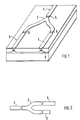
- a laser-active layer 6 extends without interruption along the entire Y-shaped structure, which is covered on its surface by a metal layer. This metal layer is electrically separated at certain points 5. The separate parts of the metal layer determine the lengths of a total of 4 individually controllable laser segments 1 to 4.
- essentially two resonators can be formed, each of which extends from the reflecting end face at the root of the Y-shaped structure to the likewise reflecting end face of one of the arms.
- a so-called gusset mode can also form to a lesser extent in a section of the Y structure that extends from the root to the branching.
- the root segment 1 and the segment 2 containing the beam splitter are thus to be regarded as common segments of the two resonator sections.
- the remaining segments 3 and 4 each influence one of the resonators.
- the current supply to the segments takes place via direct contacting of the metal layer, not shown in the figure.
- Fig. 2 shows schematically the arrangement of the segments in a semiconductor laser according to the invention.
- segment 3 is much shorter than segment 4. This leads to very different lengths of the coupled resonators.
- the laser shown therefore behaves like a Mach-Zehnder filter and modulates the flat gain curve of the laser material with a result that is much sharper than this curved Mach-Zehnder profit curve.
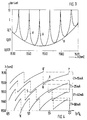
- FIG. 3 shows loss curves V of a semiconductor laser having different resonators, corresponding to the gain curves mentioned.
- the loss over the wavelength for a predetermined fixed length difference of the resonators is plotted here. If the segment currents are increased above a minimum value required for laser operation, those Fabry-Perot modes will oscillate, the wavelengths of which are at points where the losses are lowest (the gain is highest). Since the Mach-Zehnder loss curves are much more curved in the area of their minima than their envelope H, the loss curve of the laser material, there is a much higher selectivity here given the selection of individual Fabry-Perot modes and a much better side mode suppression is possible than the flat loss curve of the laser material would allow.
- a Fabry-Perot mode e.g. the ratio of the currents in the two non-common segments of the two interfering resonator sections varies.
- the envelope of the Mach-Zehnder loss curve the total current is kept constant.
- the wavelengths of the Mach-Zehnder loss curves V thus shift in their wavelength along the envelope H and the Fabry-Perot mode oscillates, which is in the range of the lowest minimum of all Mach-Zehnder loss curves. Due to the steeply increasing values of the Mach-Zehnder loss curves on both sides of their minima, closely neighboring Fabry-Perot modes cannot oscillate at the same time.
- a Fabry-Perot mode in the area of the next Mach-Zehnder loss curve only starts to oscillate when the loss curve V previously used for the mode selection has been shifted so far along the envelope curve H to higher loss values that the minimum of the next Mach-Zehnder loss curve is lower than that of the previously used loss curve and therefore has a lower loss.
- a Fabry-Perot mode with a very different wavelength then starts in the area of this next Mach-Zehnder loss curve.
- the tuning range can be chosen to be narrower or wider and so be adapted to the desired working conditions. How wide the tuning range can be set depends on the spacing of the Fabry-Perot modes and on the required effective side mode suppression, which becomes worse as the width of the tuning range increases with the sole variation of the current ratio while keeping the total current constant.
- Fig. 4 shows the result of such a laser control. Wavelengths of possible Fabry-Perot modes are shown here as a function of the ratio I3 / I4 of the currents passing through non-common segments of two resonators for different values of the total current ⁇ I1 - I4.
- I1 25 mA
- both the current ratio and the total current can be changed simultaneously.
- the changes in current ratio and total current can be coordinated with one another without problems, however, by controlling two segments, one of which only influences the total current.
- a particularly sensitive selection of individual Fabry-Perot modes with extraordinarily good side mode suppression is achieved if the distance between the Mach-Zehnder loss minima is set only slightly differently from the distance between the Fabry-Perot modes. Different Fabry-Perot modes can then be brought into coincidence with the Mach-Zehnder loss curves by slightly changing the distance between the Mach-Zehnder loss minima. These Fabry-Perot modes coinciding with Mach-Zehnder loss minima are further apart removed as immediately adjacent Fabry-Perot modes and are therefore easily selectable by shifting the loss curve of the laser material by changing the total laser current.
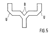
- FIG. 5 shows a central segment in which the beam is divided by a biprism B and in which curved segment parts are avoided by using beam deflecting mirrors U.
Landscapes
- Physics & Mathematics (AREA)
- Condensed Matter Physics & Semiconductors (AREA)
- General Physics & Mathematics (AREA)
- Electromagnetism (AREA)
- Optics & Photonics (AREA)
- Semiconductor Lasers (AREA)
Applications Claiming Priority (2)
| Application Number | Priority Date | Filing Date | Title |
|---|---|---|---|
| DE4212152 | 1992-04-10 | ||
| DE4212152A DE4212152A1 (de) | 1992-04-10 | 1992-04-10 | Durchstimmbarer Halbleiterlaser |
Publications (2)
| Publication Number | Publication Date |
|---|---|
| EP0565012A1 true EP0565012A1 (fr) | 1993-10-13 |
| EP0565012B1 EP0565012B1 (fr) | 1997-07-02 |
Family
ID=6456596
Family Applications (1)
| Application Number | Title | Priority Date | Filing Date |
|---|---|---|---|
| EP93105564A Expired - Lifetime EP0565012B1 (fr) | 1992-04-10 | 1993-04-03 | Laser à semi-conducteur accordable |
Country Status (4)
| Country | Link |
|---|---|
| US (1) | US5319667A (fr) |
| EP (1) | EP0565012B1 (fr) |
| JP (1) | JPH0645693A (fr) |
| DE (2) | DE4212152A1 (fr) |
Cited By (1)
| Publication number | Priority date | Publication date | Assignee | Title |
|---|---|---|---|---|
| CN105140613A (zh) * | 2015-09-12 | 2015-12-09 | 电子科技大学 | 一种单频段电调滤波型功分器 |
Families Citing this family (37)
| Publication number | Priority date | Publication date | Assignee | Title |
|---|---|---|---|---|
| DE4410780A1 (de) * | 1994-03-28 | 1995-10-05 | Siemens Ag | Integrierte Laseranordnung in Verbindung mit einem mitintegrierten Interferometer |
| DE4421043A1 (de) * | 1994-06-17 | 1995-12-21 | Sel Alcatel Ag | Interferometrischer Halbleiterlaser mit verlustarmer Lichtauskopplung und Anordung mit einem solchen Laser |
| DE4421346A1 (de) * | 1994-06-17 | 1995-12-21 | Sel Alcatel Ag | Wellenlängenwandler |
| JPH08255891A (ja) * | 1995-03-17 | 1996-10-01 | Mitsubishi Electric Corp | 光集積回路装置及びその駆動方法 |
| US6185258B1 (en) * | 1997-09-16 | 2001-02-06 | At&T Wireless Services Inc. | Transmitter diversity technique for wireless communications |
| DE10019826A1 (de) * | 2000-04-20 | 2001-10-31 | Infineon Technologies Ag | Laseranordnung |
| JP2001320127A (ja) * | 2000-05-02 | 2001-11-16 | Sumitomo Electric Ind Ltd | 半導体レーザ |
| EP1609221A4 (fr) * | 2003-03-19 | 2006-05-24 | Binoptics Corp | Lasers mordances unidirectionnels a fort smsr, et dispositif photonique a faible retroreflexion |
| CN100463312C (zh) * | 2006-11-09 | 2009-02-18 | 何建军 | V型耦合腔波长可切换半导体激光器 |
| GB2448162A (en) | 2007-04-03 | 2008-10-08 | Bookham Technology Plc | Tunable semiconductor laser |
| US9344196B1 (en) | 2009-05-28 | 2016-05-17 | Freedom Photonics, Llc. | Integrated interferometric optical transmitter |
| US8401405B2 (en) | 2009-05-28 | 2013-03-19 | Freedom Photonics, Llc. | Monolithic widely-tunable coherent receiver |
| US9316785B2 (en) | 2013-10-09 | 2016-04-19 | Skorpios Technologies, Inc. | Integration of an unprocessed, direct-bandgap chip into a silicon photonic device |
| US8615025B2 (en) * | 2009-10-13 | 2013-12-24 | Skorpios Technologies, Inc. | Method and system for hybrid integration of a tunable laser |
| US9923105B2 (en) | 2013-10-09 | 2018-03-20 | Skorpios Technologies, Inc. | Processing of a direct-bandgap chip after bonding to a silicon photonic device |
| US8368995B2 (en) | 2009-10-13 | 2013-02-05 | Skorpios Technologies, Inc. | Method and system for hybrid integration of an opto-electronic integrated circuit |
| US8611388B2 (en) | 2009-10-13 | 2013-12-17 | Skorpios Technologies, Inc. | Method and system for heterogeneous substrate bonding of waveguide receivers |
| US8630326B2 (en) * | 2009-10-13 | 2014-01-14 | Skorpios Technologies, Inc. | Method and system of heterogeneous substrate bonding for photonic integration |
| US9318868B2 (en) | 2011-09-07 | 2016-04-19 | Skorpios Technologies, Inc. | Tunable hybrid laser with carrier-induced phase control |
| US8605766B2 (en) | 2009-10-13 | 2013-12-10 | Skorpios Technologies, Inc. | Method and system for hybrid integration of a tunable laser and a mach zehnder modulator |
| US11181688B2 (en) | 2009-10-13 | 2021-11-23 | Skorpios Technologies, Inc. | Integration of an unprocessed, direct-bandgap chip into a silicon photonic device |
| US8559470B2 (en) | 2009-10-13 | 2013-10-15 | Skorpios Technologies, Inc. | Method and system for hybrid integration of a tunable laser and a phase modulator |
| US8867578B2 (en) | 2009-10-13 | 2014-10-21 | Skorpios Technologies, Inc. | Method and system for hybrid integration of a tunable laser for a cable TV transmitter |
| US9922967B2 (en) | 2010-12-08 | 2018-03-20 | Skorpios Technologies, Inc. | Multilevel template assisted wafer bonding |
| US9977188B2 (en) | 2011-08-30 | 2018-05-22 | Skorpios Technologies, Inc. | Integrated photonics mode expander |
| US9885832B2 (en) | 2014-05-27 | 2018-02-06 | Skorpios Technologies, Inc. | Waveguide mode expander using amorphous silicon |
| WO2013097200A1 (fr) * | 2011-12-30 | 2013-07-04 | 华为技术有限公司 | Laser réglable, dispositif de réseau optique et système de réseau optique |
| KR102162833B1 (ko) | 2013-01-02 | 2020-10-08 | 오이솔루션 아메리카 인코퍼레이티드 | 집적된 마하젠더 변조기를 구비한 튜너블 u-레이저 전송기 |
| US9461770B2 (en) | 2013-09-12 | 2016-10-04 | Skorpios Technologies, Inc. | Method and system for floating grid transceiver |
| US9664855B2 (en) | 2014-03-07 | 2017-05-30 | Skorpios Technologies, Inc. | Wide shoulder, high order mode filter for thick-silicon waveguides |
| US10003173B2 (en) | 2014-04-23 | 2018-06-19 | Skorpios Technologies, Inc. | Widely tunable laser control |
| JP6245656B2 (ja) * | 2015-02-16 | 2017-12-13 | 日本電信電話株式会社 | 半導体レーザ素子 |
| EP3286587A4 (fr) | 2015-04-20 | 2018-12-26 | Skorpios Technologies, Inc. | Coupleurs à sortie verticale pour des dispositifs photoniques |
| US10320152B2 (en) | 2017-03-28 | 2019-06-11 | Freedom Photonics Llc | Tunable laser |
| US10649148B2 (en) | 2017-10-25 | 2020-05-12 | Skorpios Technologies, Inc. | Multistage spot size converter in silicon photonics |
| CN108428982A (zh) * | 2018-02-28 | 2018-08-21 | 南京航空航天大学 | 一种腔体三通带滤波器 |
| US11360263B2 (en) | 2019-01-31 | 2022-06-14 | Skorpios Technologies. Inc. | Self-aligned spot size converter |
Citations (4)
| Publication number | Priority date | Publication date | Assignee | Title |
|---|---|---|---|---|
| WO1984003399A1 (fr) * | 1983-02-25 | 1984-08-30 | American Telephone & Telegraph | Dispositif optique a cavites multiples et ses applications |
| EP0162660A2 (fr) * | 1984-05-16 | 1985-11-27 | Sharp Kabushiki Kaisha | Dispositif laser semi-conducteur du type à résonateur composé |
| EP0418705A2 (fr) * | 1989-09-22 | 1991-03-27 | Alcatel SEL Aktiengesellschaft | Laser à semi-conducteur interférométrique |
| EP0516044A2 (fr) * | 1991-05-27 | 1992-12-02 | Fujitsu Limited | Source optique accordable pour créer un rayon optique cohérent à gamme d'accord large |
Family Cites Families (7)
| Publication number | Priority date | Publication date | Assignee | Title |
|---|---|---|---|---|
| US4461007A (en) * | 1982-01-08 | 1984-07-17 | Xerox Corporation | Injection lasers with short active regions |
| US4578791A (en) * | 1982-12-20 | 1986-03-25 | Trw Inc. | High-power injection laser diode structure |
| JPS62124791A (ja) * | 1985-11-25 | 1987-06-06 | Matsushita Electric Ind Co Ltd | 半導体レ−ザ |
| JPS62272579A (ja) * | 1986-05-20 | 1987-11-26 | Fujitsu Ltd | 半導体発光装置 |
| US4809288A (en) * | 1987-03-04 | 1989-02-28 | Spectra Diode Laboratories, Inc. | Hybrid Y-junction laser array |
| JPH01184892A (ja) * | 1988-01-13 | 1989-07-24 | Canon Inc | 半導体レーザ装置 |
| US4933301A (en) * | 1989-01-27 | 1990-06-12 | Spectra Diode Laboratories, Inc. | Method of forming a semiconductor laser |
-
1992
- 1992-04-10 DE DE4212152A patent/DE4212152A1/de not_active Withdrawn
-
1993
- 1993-03-22 US US08/035,918 patent/US5319667A/en not_active Expired - Lifetime
- 1993-04-03 DE DE59306825T patent/DE59306825D1/de not_active Expired - Fee Related
- 1993-04-03 EP EP93105564A patent/EP0565012B1/fr not_active Expired - Lifetime
- 1993-04-12 JP JP5084969A patent/JPH0645693A/ja active Pending
Patent Citations (4)
| Publication number | Priority date | Publication date | Assignee | Title |
|---|---|---|---|---|
| WO1984003399A1 (fr) * | 1983-02-25 | 1984-08-30 | American Telephone & Telegraph | Dispositif optique a cavites multiples et ses applications |
| EP0162660A2 (fr) * | 1984-05-16 | 1985-11-27 | Sharp Kabushiki Kaisha | Dispositif laser semi-conducteur du type à résonateur composé |
| EP0418705A2 (fr) * | 1989-09-22 | 1991-03-27 | Alcatel SEL Aktiengesellschaft | Laser à semi-conducteur interférométrique |
| EP0516044A2 (fr) * | 1991-05-27 | 1992-12-02 | Fujitsu Limited | Source optique accordable pour créer un rayon optique cohérent à gamme d'accord large |
Non-Patent Citations (3)
| Title |
|---|
| APPLIED PHYSICS LETTERS Bd. 41, Nr. 2, Juli 1982, NEW YORK, USA Seiten 112 - 114 H.A. ISMAIL 'Semiconductor Interferometric Laser' * |
| ELECTRONICS LETTERS Bd. 19, Nr. 22, Oktober 1983, LONDON, GB Seiten 926 - 927 H.A. FATAH ET AL. 'Electrical Tuning or Semiconductor Interferometric Laser' * |
| SCHILLING M., ET AL.: "INTEGRATED INTERFEROMETRIC INJECTION LASER: NOVEL FAST AND BROAD-BAND TUNABLE MONOLITHIC LIGHT SOURCE.", IEEE JOURNAL OF QUANTUM ELECTRONICS., IEEE SERVICE CENTER, PISCATAWAY, NJ., USA, vol. 27., no. 06., 1 June 1991 (1991-06-01), USA, pages 1616 - 1624., XP000229862, ISSN: 0018-9197, DOI: 10.1109/3.89985 * |
Cited By (2)
| Publication number | Priority date | Publication date | Assignee | Title |
|---|---|---|---|---|
| CN105140613A (zh) * | 2015-09-12 | 2015-12-09 | 电子科技大学 | 一种单频段电调滤波型功分器 |
| CN105140613B (zh) * | 2015-09-12 | 2018-02-13 | 电子科技大学 | 一种单频段电调滤波型功分器 |
Also Published As
| Publication number | Publication date |
|---|---|
| DE59306825D1 (de) | 1997-08-07 |
| EP0565012B1 (fr) | 1997-07-02 |
| DE4212152A1 (de) | 1993-10-14 |
| JPH0645693A (ja) | 1994-02-18 |
| US5319667A (en) | 1994-06-07 |
Similar Documents
| Publication | Publication Date | Title |
|---|---|---|
| EP0565012B1 (fr) | Laser à semi-conducteur accordable | |
| EP0890204B1 (fr) | Laser a semiconducteur declenche | |
| DE69620962T2 (de) | Wellenlängenabstimmbare Laserlichtquelle unter Verwendung eines Verbundresonators mit Halbleiterlaser | |
| EP0418705B1 (fr) | Laser à semi-conducteur interférométrique | |
| DE69407312T2 (de) | Integrierte optische Halbleiteranordnung und Herstellungsverfahren | |
| DE60222138T2 (de) | Abstimmbarer laser | |
| DE69331533T2 (de) | Verteilter Reflektor und Halbleiterlaser mit abstimmbarer Wellenlänge | |
| DE69514042T2 (de) | Wellenlängenabstimmbare Lichtquelle mit externem Resonator unter Verwendung eines Halbleiterlasers mit einer Region zur Einstellung der Phase | |
| DE69500401T2 (de) | Abstimmbarer DBR-Laser mit alternierenden Gittern | |
| DE69521157T2 (de) | Polarisationsselektiver Halbleiterlaser, Lichtsender und optisches Kommunikationssystem unter Verwendung dieses Lasers | |
| DE69505064T4 (de) | Wellenlängenabstimmbarer Halbleiterlaser | |
| DE69302749T2 (de) | Verfahren zum Justieren einer kontinuierlich abstimmbaren Lichtquelle | |
| DE69420156T2 (de) | Schnell abstimmbarer integrierter Laser | |
| DE4328777A1 (de) | Optische Filtervorrichtung | |
| DE19513198A1 (de) | Selbstpulsierender Mehrsektionslaser | |
| DE68913934T2 (de) | Verstimmbarer Halbleiterdiodenlaser mit verteilter Reflexion und Verfahren zum Herstellen eines derartigen Halbleiterdiodenlasers. | |
| DE2442652A1 (de) | Anordnung fuer durchstimmbare optische wellenleiter-komponenten | |
| DE3884503T2 (de) | Halbleiterlaser. | |
| DE69011921T2 (de) | Halbleiterlaser mit veränderbarer Emissionswellenlänge und selektives Wellenlängenfitter und Verfahren zum Betrieb derselben. | |
| DE69113100T2 (de) | Monofrequenter Laser. | |
| DE69116743T2 (de) | Phasenverschobener Halbleiterlaser mit verteilter Rückkoppelung | |
| DE69403580T2 (de) | Wellenlängenselektiver optischer Schalter | |
| DE4432410A1 (de) | Optoelektronisches Multi-Wellenlängen Bauelement | |
| DE10160502B4 (de) | Optische Mikrowellenquelle | |
| DE69632291T2 (de) | Lichtquelle mit variablen Wellenlänge unter Verwendung eines Lasers, Verfahren zur Wellenlängenregelung, optisches Kommunikationssystem und Verfahren zur optischen Kommunikation |
Legal Events
| Date | Code | Title | Description |
|---|---|---|---|
| PUAI | Public reference made under article 153(3) epc to a published international application that has entered the european phase |
Free format text: ORIGINAL CODE: 0009012 |
|
| AK | Designated contracting states |
Kind code of ref document: A1 Designated state(s): DE FR GB NL SE |
|
| 17P | Request for examination filed |
Effective date: 19940316 |
|
| 17Q | First examination report despatched |
Effective date: 19950405 |
|
| GRAG | Despatch of communication of intention to grant |
Free format text: ORIGINAL CODE: EPIDOS AGRA |
|
| GRAH | Despatch of communication of intention to grant a patent |
Free format text: ORIGINAL CODE: EPIDOS IGRA |
|
| GRAH | Despatch of communication of intention to grant a patent |
Free format text: ORIGINAL CODE: EPIDOS IGRA |
|
| GRAA | (expected) grant |
Free format text: ORIGINAL CODE: 0009210 |
|
| AK | Designated contracting states |
Kind code of ref document: B1 Designated state(s): DE FR GB NL SE |
|
| REF | Corresponds to: |
Ref document number: 59306825 Country of ref document: DE Date of ref document: 19970807 |
|
| GBT | Gb: translation of ep patent filed (gb section 77(6)(a)/1977) |
Effective date: 19971003 |
|
| ET | Fr: translation filed | ||
| PLBE | No opposition filed within time limit |
Free format text: ORIGINAL CODE: 0009261 |
|
| 26N | No opposition filed | ||
| REG | Reference to a national code |
Ref country code: FR Ref legal event code: CD |
|
| REG | Reference to a national code |
Ref country code: GB Ref legal event code: IF02 |
|
| PGFP | Annual fee paid to national office [announced via postgrant information from national office to epo] |
Ref country code: SE Payment date: 20020327 Year of fee payment: 10 |
|
| PGFP | Annual fee paid to national office [announced via postgrant information from national office to epo] |
Ref country code: NL Payment date: 20020328 Year of fee payment: 10 |
|
| PG25 | Lapsed in a contracting state [announced via postgrant information from national office to epo] |
Ref country code: SE Free format text: LAPSE BECAUSE OF NON-PAYMENT OF DUE FEES Effective date: 20030404 |
|
| PG25 | Lapsed in a contracting state [announced via postgrant information from national office to epo] |
Ref country code: NL Free format text: LAPSE BECAUSE OF NON-PAYMENT OF DUE FEES Effective date: 20031101 |
|
| NLV4 | Nl: lapsed or anulled due to non-payment of the annual fee |
Effective date: 20031101 |
|
| EUG | Se: european patent has lapsed | ||
| PGFP | Annual fee paid to national office [announced via postgrant information from national office to epo] |
Ref country code: GB Payment date: 20040414 Year of fee payment: 12 |
|
| PGFP | Annual fee paid to national office [announced via postgrant information from national office to epo] |
Ref country code: DE Payment date: 20040415 Year of fee payment: 12 |
|
| PGFP | Annual fee paid to national office [announced via postgrant information from national office to epo] |
Ref country code: FR Payment date: 20040419 Year of fee payment: 12 |
|
| PG25 | Lapsed in a contracting state [announced via postgrant information from national office to epo] |
Ref country code: GB Free format text: LAPSE BECAUSE OF NON-PAYMENT OF DUE FEES Effective date: 20050403 |
|
| PG25 | Lapsed in a contracting state [announced via postgrant information from national office to epo] |
Ref country code: DE Free format text: LAPSE BECAUSE OF NON-PAYMENT OF DUE FEES Effective date: 20051101 |
|
| GBPC | Gb: european patent ceased through non-payment of renewal fee |
Effective date: 20050403 |
|
| PG25 | Lapsed in a contracting state [announced via postgrant information from national office to epo] |
Ref country code: FR Free format text: LAPSE BECAUSE OF NON-PAYMENT OF DUE FEES Effective date: 20051230 |
|
| REG | Reference to a national code |
Ref country code: FR Ref legal event code: ST Effective date: 20051230 |