EP0565056A2 - Dispositif de détection d'information de déplacement - Google Patents
Dispositif de détection d'information de déplacement Download PDFInfo
- Publication number
- EP0565056A2 EP0565056A2 EP93105692A EP93105692A EP0565056A2 EP 0565056 A2 EP0565056 A2 EP 0565056A2 EP 93105692 A EP93105692 A EP 93105692A EP 93105692 A EP93105692 A EP 93105692A EP 0565056 A2 EP0565056 A2 EP 0565056A2
- Authority
- EP
- European Patent Office
- Prior art keywords
- light
- light beam
- light beams
- diffraction grating
- interference
- Prior art date
- Legal status (The legal status is an assumption and is not a legal conclusion. Google has not performed a legal analysis and makes no representation as to the accuracy of the status listed.)
- Granted
Links
Images








Classifications
-
- G—PHYSICS
- G01—MEASURING; TESTING
- G01D—MEASURING NOT SPECIALLY ADAPTED FOR A SPECIFIC VARIABLE; ARRANGEMENTS FOR MEASURING TWO OR MORE VARIABLES NOT COVERED IN A SINGLE OTHER SUBCLASS; TARIFF METERING APPARATUS; MEASURING OR TESTING NOT OTHERWISE PROVIDED FOR
- G01D5/00—Mechanical means for transferring the output of a sensing member; Means for converting the output of a sensing member to another variable where the form or nature of the sensing member does not constrain the means for converting; Transducers not specially adapted for a specific variable
- G01D5/26—Mechanical means for transferring the output of a sensing member; Means for converting the output of a sensing member to another variable where the form or nature of the sensing member does not constrain the means for converting; Transducers not specially adapted for a specific variable characterised by optical transfer means, i.e. using infrared, visible, or ultraviolet light
- G01D5/32—Mechanical means for transferring the output of a sensing member; Means for converting the output of a sensing member to another variable where the form or nature of the sensing member does not constrain the means for converting; Transducers not specially adapted for a specific variable characterised by optical transfer means, i.e. using infrared, visible, or ultraviolet light with attenuation or whole or partial obturation of beams of light
- G01D5/34—Mechanical means for transferring the output of a sensing member; Means for converting the output of a sensing member to another variable where the form or nature of the sensing member does not constrain the means for converting; Transducers not specially adapted for a specific variable characterised by optical transfer means, i.e. using infrared, visible, or ultraviolet light with attenuation or whole or partial obturation of beams of light the beams of light being detected by photocells
- G01D5/36—Forming the light into pulses
- G01D5/38—Forming the light into pulses by diffraction gratings
Definitions
- the present invention relates to a displacement information detection apparatus and, more particularly, to an apparatus suitable for optical displacement sensors such as an encoder, a speed sensor, an acceleration sensor, and the like, which measure a displacement and a speed of an object by utilizing the fact that when a light beam radiated onto an object being displaced is diffracted or scattered, the diffracted or scattered light beam is phase-modulated according to the displacement or the moving speed of the object.
- optical displacement sensors such as an encoder, a speed sensor, an acceleration sensor, and the like
- optical displacement sensors e.g., an optical encoder, a laser Doppler speedometer, a laser interferometer, and the like, for obtaining a physical quantity such as movement or displacement of an object with high precision by radiating light onto the object are widely used mainly in the fields of NC working machines, OA equipment, robots, and the like.
- a conventional displacement sensor for example, Japanese Laid-Open Utility Model Application No. 1-180615 and Japanese Laid-Open Patent Application No. 62-121314 disclose optical encoders.
- Japanese Laid-Open Patent Application No. 2-262064 discloses a laser Doppler speedometer.
- the displacement sensor In consideration of an application of the displacement sensor to wider fields, the displacement sensor is demanded to have a more compact structure (on the order of mm), and higher precision and resolution (on the order of 0.1 ⁇ m). If the displacement sensor has a size on the order of mm, it may be used while being directly adhered to an object to be measured by, e.g., an adhesive. For this reason, the displacement sensor can be used for smaller devices, and the application field range can be remarkably widened. However, it is difficult for the conventional displacement sensor to achieve both a compact structure and high-precision/high-resolution characteristics.
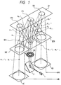
- Fig. 1 is a perspective view showing main part of an optical encoder according to the first embodiment of the present invention.
- a member 1 is a light-emitting element for emitting light, and has a size on the order of several hundreds of ⁇ m.
- the light-emitting element of this embodiment comprises a semiconductor laser element for generating a laser beam having a wavelength of 780 nm.
- the light-emitting element may comprise, e.g., a light-emitting diode in place of the semiconductor laser element.
- Light emitted from the light-emitting element 1 arranged on a horizontal plane is reflected by a mirror 2 whose mirror surface is formed to have an inclination of 45° so as to propagate in the vertical direction.
- a prism may be used in place of the mirror.
- a transparent glass plate (not shown) as a light transmission member is arranged in the propagation direction of the light.
- Three diffraction grating portions 32A, 32B, and 32C having the same pitch are formed on one surface of the glass plate.
- the pitch P of each diffraction grating portion is set to be 1.6 ⁇ m in this embodiment.
- Light-receiving elements 4B and 4C are arranged to receive light and to photoelectrically convert the received light.
- the light-receiving element includes a photodiode, an avalanche photodiode, a PIN photodiode, a CCD, or a light-receiving IC having such a light-receiving portion, and a circuit for amplifying or processing an output photocurrent.
- the light-receiving elements 4B and 4C detect signals having a phase difference therebetween.
- a divergent light beam emitted from the light-emitting element 1 is deflected by the mirror 2 in the vertical direction, and is converted into a divergent light beam R having a predetermined beam diameter by a mask 30 having a circular aperture.
- This light beam is transmission-diffracted by the diffraction grating 32A formed on one surface of the glass plate, and emerges as a plurality of split light beams including a 0th-order diffracted light beam R0, a +1st-order diffracted light beam R+1, and a -1st-diffracted light beam R ⁇ 1.
- the light beam R0 transmitted straight through the diffraction grating 32A is reflection-diffracted by a point P1 on a diffraction grating 21 formed on a scale, and is split into a +1st-order diffracted light beam R0+1 and a -1st-order diffracted light beam R0 ⁇ 1 so as to be phase-modulated.
- phase of the +1st-order diffracted light beam R0+1 is shifted by +2 ⁇ x/P
- the phase of the -1st-order diffracted light beam R0 ⁇ 1 is shifted by -2 ⁇ x/P (where x is the moving amount of the diffraction grating 21, and P is the pitch of the diffraction grating 21).
- the +1st-order diffracted light beam R0+1 is transmission-diffracted by the diffraction grating 32B formed on one surface of the glass plate, and is split into a 0th-order diffracted light beam R0+10, a -1st-order diffracted light beam R0+1 ⁇ 1, and other light beams. Of these light beams, the -1st-order diffracted light beam R0+1 ⁇ 1 is extracted in a direction perpendicular to the diffraction grating surface, and the phase of the wave surface at that time is +2 ⁇ x/P.
- the -1st-order diffracted light beam R0 ⁇ 1 is transmission-diffracted by the diffraction grating 32C formed on one surface of the glass plate, and is split into a 0th-order diffracted light beam R0 ⁇ 10, a +1st-order diffracted light beam R0 ⁇ 1+1, and other light beams.
- the +1st-order diffracted light beam R0 ⁇ 1+1 is extracted in a direction perpendicular to the diffraction grating surface, and the phase of the wave surface at that time is -2 ⁇ x/P.
- phase relationship of the grating arrangement of the diffraction grating 32B is shifted by P/4 from that of the diffraction grating 32C
- the light beam R+1 which is +1st-order-diffracted by the diffraction grating 32A formed on one surface of the glass plate, is reflection-diffracted by a point P2 on the diffraction grating 21 on the scale 20, and is split into a -1st-order diffracted light beam R+1 ⁇ 1, a 0th-order diffracted light R+10, and other light beams so as to be phase-modulated.
- the -1st-order diffracted light beam R+1 ⁇ 1 is incident on the diffraction grating 32B while its phase is shifted by -2 ⁇ x/P, and the phase of the wave surface of the 0th-order diffracted light R+10, which is transmitted straight through the diffraction grating, is -2 ⁇ x/P.
- the light beam R ⁇ 1 which is -1st-order-diffracted by the diffraction grating 32A formed on one surface of the glass plate 3, is reflection-diffracted by a point P3 on the diffraction grating 21 on the scale, and is split into a +1st-order diffracted light beam R ⁇ 1+1, a 0th-order diffracted light R ⁇ 10, and other light beams so as to be phase-modulated.
- the +1st-order diffracted light beam R ⁇ 1+1 is incident on the diffraction grating 32C while its phase is shifted by +2 ⁇ x/P, and the phase of the wave surface of the 0th-order diffracted light R ⁇ 10, which is transmitted straight through the diffraction grating, is +2 ⁇ x/P.
- a light/dark signal for one period is generated every time the diffraction grating 21 on the scale 20 is moved by a 1/2 pitch.
- a light/dark signal for one period is generated every time the diffraction grating 21 on the scale is moved by a 1/2 pitch, and the light/dark timing of this signal is shifted by a 1/4 period from that of the light-receiving element 4B.
- the arrangement for forming a divergent light beam is not limited to that shown in Fig. 1.
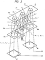
- a lens 31 may be used in place of the mask, as shown in Fig. 2 so as to form a proper divergent light beam.
- a divergent light beam i.e., a spherical wave is incident on the light-receiving element.
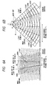
- Figs. 6A and 6B are views for comparing a case wherein a light beam is a parallel light beam (plane wave) and a case wherein a light beam is a divergent light beam (spherical wave).
- the light beam is a parallel light beam, i.e., a plane wave
- a pitch P2 of interference fringes upon interference of two parallel light beams is determined by an angle ⁇ 2 between the two light beams. Therefore, as shown in Fig.
- the interference state undesirably changes. More specifically, in the case of the plane wave, the scale is required to have high mounting precision with respect to the encoder head.
- a pitch P1 of interference fringes depends on the ratio ( ⁇ X/R) of a separation amount ⁇ X at light-emitting points A and B and a distance R from each light-emitting point to the observation surface (the spherical wave on the observation surface has a curvature 1/R) independently of an angle ⁇ 1 formed between main rays of the light beams A and B.
- the ratio ⁇ X/R becomes close to 0, the pitch P1 of the interference fringes is increased, and consequently, a change in interference state becomes small.
- the spherical wave can decrease a variation in output caused by mounting errors of the scale in the rotational direction, as shown in Fig. 5, as compared to the plane wave.
- Fig. 3 shows an arrangement of an encoder according to the second embodiment of the present invention, wherein spherical waves are incident on light-receiving elements like in the first embodiment.
- a lens 31A converts light emitted from a light-emitting element into a convergent light beam or a parallel light beam
- lenses 31B and 31C are arranged to convert the convergent or parallel light beam into a proper divergent light beam, and to cause them to be incident on the light-receiving elements 4B and 4C.
- These lenses 31A, 31B, and 31C, and the diffraction gratings 32A, 32B, and 32C are respectively formed on the front and rear surfaces of a transparent glass plate.
- a divergent light beam emitted from the light-emitting element 1 is deflected by the mirror 2, and is converted into a convergent or substantially parallel light beam R by the lens 31A.
- the convergent or parallel light beam R is radiated onto the diffraction grating 32A.
- the detection principle itself of the encoder is the same as that of the above embodiment. In this embodiment, however, convergent or parallel light beams R+1 ⁇ 10 and R0+1 ⁇ 1 whose optical paths are caused to overlap each other by the diffraction grating 32B are converted by the lens 31B into proper divergent interference light (spherical wave), and the interference light is incident on the photoelectric element 4B.
- convergent or parallel light beams R ⁇ 1+10 and R0 ⁇ 1+1 whose optical paths are caused to overlap each other by the diffraction grating 32C are converted by the lens 31C into proper divergent interference light (spherical wave), and the interference light is incident on the photoelectric element 4C.
- the interference light beams are converted into divergent light beams immediately before the photoelectric elements 4B and 4C, the amounts of light beams incident on the photoelectric elements 4B and 4C can be increased. Therefore, a stable signal having a good S/N ratio can be obtained in addition to the effect of the first embodiment.
- Fig. 4 shows an arrangement of an encoder according to the third embodiment of the present invention, wherein spherical waves are incident on light-receiving elements like in the first and second embodiments.
- the lens 31A focuses light emitted from the light-emitting element 1.
- the converged light is temporarily focused near the scale diffraction grating 21, and is then incident on the photoelectric elements 4B and 4C as divergent light.
- Fig. 7 shows an arrangement of an encoder according to the fourth embodiment of the present invention, wherein spherical waves are incident on light-receiving elements like in the first to third embodiments.
- a light beam is caused to converge on a middle point along an optical path extending between a split diffraction grating and a synthesizing diffraction grating, so that a change in interference state caused by the mounting error can be suppressed.
- a variation in output caused by the change in interference state on the light-receiving surface is minimized, and a signal less influenced by mounting errors and having a good S/N ratio can be obtained.
- the encoder is constituted by one light-emitting element, at least one mask or lens, three diffraction gratings provided to a measurement head, a diffraction grating provided to a scale, and two photoelectric elements, a compact, high-precision, and low-cost encoder, which allows easy mounting and assembling processes, has a simple structure, and is easy to handle, can be constituted.
- Fig. 7 is a perspective view showing an arrangement of an optical encoder according to this embodiment.
- the same reference numerals in Fig. 7 denote the same parts as in the above embodiments.
- a divergent light beam emitted from the light-emitting element 1 is deflected by the mirror 2, and is converted into a proper convergent light beam by the lens 31A.
- the convergent light beam is transmission-diffracted by the diffraction grating 32A, and emerges therefrom as three split beams, i.e., a 0th-order diffracted light beam R0, a +1st-order diffracted light beam R+1, and a -1st-order diffracted light beam R ⁇ 1.
- the light beam R0 transmitted straight through the diffraction grating 32A is reflection-diffracted by a point P1 on the diffraction grating 21 formed on the scale, and is split into a +1st-order diffracted light beam R0+1 and a -1st-order diffracted light beam R0 ⁇ 1 so as to be phase-modulated. These light beams respectively converge on points 011 and 012 near the diffraction grating 21.
- phase of the +1st-order diffracted light beam R0+1 is shifted by +2 ⁇ x/P
- the phase of the 1st-order diffracted light beam R0 ⁇ 1 is shifted by -2 ⁇ x/P (where x is the moving amount of the diffraction grating 21, and P is the pitch of the diffraction grating 21).
- the +1st-order diffracted light beam R0+1 is transmission-diffracted by the diffraction grating 32B, and is split into a 0th-order diffracted light beam R0+10, a -1st-order diffracted light beam R0 ⁇ 1 ⁇ 1, and other light beams. Of these light beams, the -1st-order diffracted light beam R0 ⁇ 1 ⁇ 1 is extracted in a direction perpendicular to the diffraction grating surface. The phase shift of the wave surface of this light beam is +2 ⁇ x/P unless the diffraction grating 32B suffers from a phase shift.
- the -1st-order diffracted light beam R0 ⁇ 1 is transmission-diffracted by the diffraction grating 32C, and is split into a 0th-order diffracted light beam R0 ⁇ 10, a +1st-order diffracted light beam R0 ⁇ 1+1, and other light beams. Of these light beams, the +1st-order diffracted light beam R0 ⁇ 1+1 is extracted in a direction perpendicular to the diffraction grating surface.
- the phase shift of the wave surface of this light beam is -2 ⁇ x/P unless the diffraction grating 32C suffers from a phase shift.
- phase relationship of the grating arrangement of the diffraction grating 32B is shifted by P/4 from that of the diffraction grating 32C
- the light beam R+1 which is +1st-order-diffracted by the diffraction grating 32A, converges on a point 02 near the diffraction grating 21. Thereafter, the light beam R+1 is reflection-diffracted by a point P2 on the diffraction grating 21 on the scale, and is split into a -1st-order diffracted light beam R+1 ⁇ 1, a 0th-order diffracted light beam R+10, and other light beams so as to be phase-modulated.
- the -1st-order diffracted light beam R+1 ⁇ 1 is incident on the diffraction grating 32B while its phase is shifted by -2 ⁇ x/P, and the phase of the wave surface of the 0th-order diffracted light R+10, which is transmitted straight through the diffraction grating, is -2 ⁇ x/P.
- the light beam R ⁇ 1 which is -1st-order-diffracted by the diffraction grating 32A, converges on a point 03 near the diffraction grating 21. Thereafter, the light beam R ⁇ 1 is reflection-diffracted by a point P3 on the diffraction grating 21 on the scale, and is split into a +1st-order diffracted light beam R ⁇ 1+1, a 0th-order diffracted light R ⁇ 10, and other light beams so as to be phase-modulated.
- the +1st-order diffracted light beam R ⁇ 1+1 is incident on the diffraction grating 32C while its phase is shifted by +2 ⁇ x/P, and the phase of the wave surface of the 0th-order diffracted light R ⁇ 10, which is transmitted straight through the diffraction grating, is +2 ⁇ x/P.
- the above-mentioned convergence point of each light beam is set at a middle optical path length position of the optical path length of the optical path from the grating 32A to the grating 32B or 32C of the corresponding light beam. More specifically, if the optical path lengths of the light beams R+1 ⁇ 1 and R0+1 from the diffraction grating 21 to the diffraction grating 32B are respectively represented by L and L', the convergence points of the light beam R+1 ⁇ 1(i.e., the light beam R+1 ) and the light beam R0+1 are set to be formed at positions having an optical path length of about (L + L')/2 from the diffraction grating 32B. The same applies to the light beams R ⁇ 1+1 and R0 ⁇ 1.
- a light/dark signal for one period is generated every time the diffraction grating 21 on the scale is moved by a 1/2 pitch.
- a light/dark signal for one period is generated every time the diffraction grating 21 on the scale is moved by a 1/2 pitch, and the light/dark timing of this signal is shifted by a 1/4 period from that of the photoelectric element 4B.
- the above-mentioned apparatus has a very simple interference optical system, when the lenses and the diffraction gratings are formed on two surfaces of a glass plate by, e.g., a replica manufacturing method, a compact and low-cost encoder can be realized.
- the following merits can be particularly expected.
- Fig. 8 shows the principle of the apparatus shown in Fig. 7, and the mirror 2 is not illustrated.
- the main rays of the two interfered light beams coincide with each other, and the spherical waves of these light beams always define a concentric state.
- an azimuth angular displacement ⁇ shown in Fig. 8 is given to the scale, an angular difference ( ⁇ 1) is formed between the main rays of the two light beams, as shown in Fig. 9.
- interference nonuniformity may slightly occur on the sensor surfaces due to the displacement between the spherical waves of the two light beams although its level is considerably smaller than that caused by plane waves.
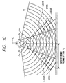
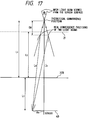
- Fig. 10 illustrates a state wherein the main rays of two light beams A and B having spherical waves have an angular difference therebetween.
- Points O A and O B respectively represent convergence points of the two light beams A and B
- a A and A B represent the main rays of the two light beams A and B
- W represents the wave surface.
- the main rays seem to cross at a specific position (a point C in Fig. 10).
- the position where the main rays seem to cross will be referred to as a crossing position hereinafter. If the convergence positions of the light beams do not coincide with the crossing position, two point light sources (convergence points) are undesirably separated from each other.
- a pitch P1 of the interference fringes on the sensor surface depends on the ratio ( ⁇ X/R) of a separation amount ⁇ X of the convergence points O A and O B to a distance R from the point light source to the observation surface (the spherical wave on the observation surface has a curvature 1/R) independently of an angle ⁇ 1 formed between the main rays of the light beams A and B.
- the pitch P1 of the interference fringes is increased, and as a result, a change in interference state is decreased.
- ⁇ X 0
- the pitch P1 of the interference fringes becomes an infinity and the interference state is left unchanged, regardless of the value of ⁇ 1.
- an inter-grating distance L2 is defined as a unit length (the crossing position of the main rays of the two interfered light beams is expressed by the distances from the gratings 32B and 32C for synthesizing the light beams: when the sign is negative, it represents a direction to separate away from the gratings 32B and 32C when viewed from sensor surfaces 4b and 4c; when the sign is positive, it represents a direction to approach the gratings 32B and 32C).
- the sign when the sign is negative, it represents a direction to separate away from the gratings 32B and 32C when viewed from sensor surfaces 4b and 4c; when the sign is positive, it represents a direction to approach the gratings 32B and 32C).
- the crossing position of the two interfered light beams is almost constant independently of the wavelength ⁇ , the grating pitch P, and the azimuth angle ⁇ in this optical system, and is a middle optical path length position of an optical path between the gratings 32A and 32B (an optical path of light split by the grating 32A until it is incident on the grating 32B after it is reflection-diffracted by the scale 21) or an optical path between the gratings 32A and 32C (an optical path of light split by the grating 32A until it is incident on the grating 32C after it is reflection-diffracted by the scale 20), i.e., a position corresponding to an optical path length half the optical path length of the optical path from the grating 32A to the grating 32B or 32C.
- each convergence point is set at an optical path length position half the optical path length of the optical path from the grating 32A to the grating 32B or 32C (i.e., a position separated by an optical path length of about (L + L')/2 from the diffraction grating 32B or 32C where L and L' are the optical path lengths of the two interfered diffracted light beams from the diffraction grating 21 to the diffraction grating 32B or 32C), the crossing position of the two interfered light beams substantially coincides with the convergence position, the spherical waves of the two light beams define a concentric state, and no interference fringes are theoretically generated on the sensor surface.
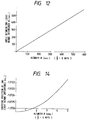
- Fig. 14 is a graph showing the relationship between the azimuth angle ⁇ and the crossing position.
- the crossing position finely moves in a direction to approach the scale 20 in practice as the azimuth angle ⁇ is increased.
- the reason for this is as follows.
- the direction of reflection diffraction begins to be displaced in the Y-and X-axis directions in Fig. 8.
- the displacement in the Y-axis direction can be ignored when the azimuth angle ⁇ is small or when the diffraction angle is small.
- the crossing position of the two interfered light beams can be calculated according to the displacement in the X-axis direction alone, and almost coincides with the above-mentioned middle position of the optical path between the gratings.
- the azimuth angle ⁇ or the diffraction angle is increased from the above-mentioned case, the displacement in the Y-axis direction cannot be ignored, and the crossing position of the two interfered light beams moves in the direction to approach the scale.
- the moving amount of the crossing position is negligible as compared to the inter-grating distance, as can be understood from Fig. 14.
- the relative angle (azimuth angle) between the scale and the diffraction gratings 32A, 32B, and 32C for splitting and synthesizing the light beams can be suppressed.
- the inter-grating distance is set to be 1 mm
- P 1.6 ⁇ m
- ⁇ 0.78 ⁇ m
- the theoretical convergence position is a position separated by -1.072657 mm from the diffraction grating 32B or 32C for synthesizing the light beams.
- the crossing position of the main rays of the two interfered light beams R0+1 ⁇ 1 and R+1 ⁇ 10 when viewed from the sensor surface is calculated.
- the vectors of the light beams emerging from the synthesizing grating 32B of these two light beams are respectively given by equations (6) and (7).
- equations (5) and the interval between the diffraction gratings are used, crossing points between the two light beams and each diffraction grating can be obtained.
- the crossing points between the two beams and the grating 32B i.e., exit positions P0 and P+1 of rays on the grating 32B, can be calculated.
- a line passing the point P0 and parallel to the vector (U2) given by equations (6), and a line passing the point P+1 and parallel to the vector (U2') given by equations (7) can be calculated.
- the calculated position is the crossing position to be obtained.
- the crossing position will be considered to have the grating 32B for synthesizing the two light beams as the origin of the Z-axis and the direction of the scale 20 as a negative direction.
- the position in the X- and Y-directions can be considered as follows.
- Angles formed between a perpendicular to the grating 32B and the two light beams R0+1 ⁇ 1 and R+1 ⁇ 10 separated by an azimuth are almost equal to each other in opposite directions.
- the crossing position, in the X- and Y-directions, of the two lines is near the optical axis when there is no azimuth. More specifically, as the crossing position of the two lines, the optical axis direction when there is no azimuth, i.e., the position in the Z-direction need only be considered. In the following description, only the position in the Z-direction will be considered.
- the number of interference fringes on the entire sensor surface is one.
- the number H 0n of interference fringes on the sensor surface is given by:
- V (I max - I min )/(I max + I min ) where I max and I min are the maximum and minimum amplitudes of the light-receiving element output.
- n s the number of interference fringes in a sensor region
- V max and V min the maximum and minimum outputs of the light-receiving element
- the inter-grating distance is set to be 1 mm
- P 1.6 ⁇ m
- ⁇ 0.78 ⁇ m
- the theoretical convergence position is a position separated by -1.072657 mm from the diffraction gratings 32B and 32C for synthesizing the light beams.
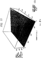
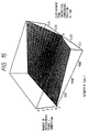
- the relationship among the azimuth angle ⁇ , the number n of interference fringes, and the displacement D z from the theoretical convergence position is as shown in Figs. 15 and 16 from equation (12). If a decrease in output is within 20%, the maximum number of interference fringes generated on the sensor surface can be defined from equation (13). If the diameter of the sensor is assumed to be 1 mm, the maximum allowable number of fringes is 0.36. If the allowable range of the azimuth angle is defined to be a maximum of 480 seconds (8 minutes), the corresponding region of the displacement D z from the theoretical convergence position is determined from Fig. 16, and the region satisfying the above-mentioned conditions is indicated by hatching in Fig. 16. As can be understood from Fig.
- target stability can be obtained by constituting an optical system which focuses light beams within a range satisfying: -0.29 mm ⁇ D z ⁇ 0.22 mm In this manner, with the arrangement shown in Fig. 7, an encoder in which the output is less influenced by mounting errors of the scale, and easy mounting and assembling processes are allowed, can be realized.
- the phases of signals output from the sensors 4C and 4B are shifted by 90°, and two-phase signals can be obtained as signal outputs.
- Fig. 19 is a block diagram showing an embodiment corresponding to an application of the above-mentioned encoder, i.e., a driving system using the encoder.
- An encoder 101 is attached to a driving output portion of or a moving portion of an object to be driven by a driving means 100 having a driving source such as a motor, an actuator, an engine, or the like, and detects a displacement state such as a displacement amount, a displacement speed, and the like.
- a driving source such as a motor, an actuator, an engine, or the like
- a displacement state such as a displacement amount, a displacement speed, and the like.
- the detection output of the encoder 101 is fed back to a controlling means 102, and the controlling means 102 supplies a driving signal to the driving means 100 so as to attain a state set by a setting up means 103.
- the driving state set by the setting up means 103 can be obtained.
- a driving system can be widely applied to, e.g., OA equipment such as typewriters, printers, copying machines, facsimile systems, and the like, video equipment such as cameras, video apparatuses, and the like, information recording/reproduction apparatuses, robots, working machines, manufacturing machines, transport machines, and also to any other apparatuses having driving means.
- a displacement information detection apparatus for detecting relative displacement information between itself and an object to be detected including an illumination system for rediating coherent light; a first diffraction grating for splitting the coherent light from said illumination system into first and second light beams, the first and second light beams being radiated onto the object; a second diffraction grating for synthesizing the first and second light beams emerging from the object, an interfernce light beam being generated by the synthesizing operation of said second diffraction grating; and a light-receiving element for detecting the interference light beam, the relative displacement information between said apparatus and the object being detected upon reception of the interference light beam by said light-receiving element, wherein said apparatus is arranged, so that a wave surface of the interference light beam incident on said light-receiving element has a convex spherical shape with respect to a propagation direction of the light beam.
Landscapes
- Physics & Mathematics (AREA)
- General Physics & Mathematics (AREA)
- Optical Transform (AREA)
Applications Claiming Priority (4)
| Application Number | Priority Date | Filing Date | Title |
|---|---|---|---|
| JP8544792 | 1992-04-07 | ||
| JP85447/92 | 1992-04-07 | ||
| JP33740392A JP2862448B2 (ja) | 1991-12-20 | 1992-12-17 | 光学式変位センサ及びこれを用いた駆動システム |
| JP337403/92 | 1992-12-17 |
Publications (3)
| Publication Number | Publication Date |
|---|---|
| EP0565056A2 true EP0565056A2 (fr) | 1993-10-13 |
| EP0565056A3 EP0565056A3 (en) | 1995-05-17 |
| EP0565056B1 EP0565056B1 (fr) | 1998-09-02 |
Family
ID=26426451
Family Applications (1)
| Application Number | Title | Priority Date | Filing Date |
|---|---|---|---|
| EP93105692A Expired - Lifetime EP0565056B1 (fr) | 1992-04-07 | 1993-04-06 | Dispositif de détection d'information de déplacement |
Country Status (3)
| Country | Link |
|---|---|
| US (1) | US5390022A (fr) |
| EP (1) | EP0565056B1 (fr) |
| DE (1) | DE69320678T2 (fr) |
Cited By (2)
| Publication number | Priority date | Publication date | Assignee | Title |
|---|---|---|---|---|
| EP0651232A1 (fr) * | 1993-10-29 | 1995-05-03 | Canon Kabushiki Kaisha | Codeur rotatif |
| EP0679870A3 (fr) * | 1994-04-27 | 1997-04-16 | Canon Kk | Capteur optique de déplacement. |
Families Citing this family (24)
| Publication number | Priority date | Publication date | Assignee | Title |
|---|---|---|---|---|
| JPH074993A (ja) * | 1993-03-23 | 1995-01-10 | Ricoh Co Ltd | エンコーダ装置 |
| JP3028716B2 (ja) * | 1993-09-29 | 2000-04-04 | キヤノン株式会社 | 光学式変位センサ |
| DE69530757T2 (de) * | 1994-01-24 | 2004-03-18 | Asml Holding, N.V. | Gitter-gitter interferometrisches ausrichtsystem |
| JPH08210814A (ja) * | 1994-10-12 | 1996-08-20 | Canon Inc | 光学式変位測定装置 |
| JPH08210824A (ja) * | 1995-02-07 | 1996-08-20 | Canon Inc | 回転検出装置及び回転制御装置 |
| JPH08219812A (ja) * | 1995-02-15 | 1996-08-30 | Canon Inc | 変位情報検出装置、変位情報検出用スケール及びこれを用いたドライブ制御装置 |
| EP0729013B1 (fr) * | 1995-02-21 | 2002-07-17 | Canon Kabushiki Kaisha | Appareil de détection de déplacement et système de commande utilisant celui-ci |
| US6229140B1 (en) | 1995-10-27 | 2001-05-08 | Canon Kabushiki Kaisha | Displacement information detection apparatus |
| US6151185A (en) * | 1996-09-05 | 2000-11-21 | Canon Kabushiki Kaisha | Position detecting apparatus, positioning apparatus, and information recording apparatus using the same |
| US6631047B2 (en) | 1997-09-22 | 2003-10-07 | Canon Kabushiki Kaisha | Interference device, position detecting device, positioning device and information recording apparatus using the same |
| JPH11351813A (ja) | 1998-06-08 | 1999-12-24 | Canon Inc | 干渉装置及びそれを用いた位置検出装置 |
| US6407815B2 (en) * | 1998-07-02 | 2002-06-18 | Sony Precision Technology Inc. | Optical displacement measurement system |
| JP4365927B2 (ja) | 1999-03-12 | 2009-11-18 | キヤノン株式会社 | 干渉計測装置及び格子干渉式エンコーダ |
| DE60033075T3 (de) | 1999-04-16 | 2012-08-30 | Canon K.K. | Kodierer |
| JP2000321021A (ja) | 1999-05-10 | 2000-11-24 | Canon Inc | 干渉装置、変位測定装置、及びそれを用いた情報記録又は/及び再生装置 |
| JP4846909B2 (ja) | 2000-02-15 | 2011-12-28 | キヤノン株式会社 | 光学式エンコーダ及び回折格子の変位測定方法 |
| JP2001336952A (ja) | 2000-05-26 | 2001-12-07 | Canon Inc | 測定装置 |
| GB0413710D0 (en) * | 2004-06-21 | 2004-07-21 | Renishaw Plc | Scale reading apparatus |
| DE102005053787B4 (de) * | 2005-11-09 | 2019-11-28 | Dr. Johannes Heidenhain Gmbh | Optische Abtasteinheit sowie Verfahren zur Montage |
| KR101624505B1 (ko) * | 2009-09-24 | 2016-05-26 | 삼성전자주식회사 | 3-d 포인팅 감지 장치 및 방법 |
| DE102010003157B4 (de) * | 2010-03-23 | 2019-10-24 | Dr. Johannes Heidenhain Gmbh | Vorrichtung zur interferentiellen Abstandsmessung |
| NL2006743A (en) * | 2010-06-09 | 2011-12-12 | Asml Netherlands Bv | Position sensor and lithographic apparatus. |
| US8604413B2 (en) * | 2011-06-13 | 2013-12-10 | Mitutoyo Corporation | Optical encoder including displacement sensing normal to the encoder scale grating surface |
| DE102013203713A1 (de) * | 2013-03-05 | 2014-02-13 | Carl Zeiss Smt Gmbh | Inkrementalgeber und Lithographievorrichtung |
Citations (3)
| Publication number | Priority date | Publication date | Assignee | Title |
|---|---|---|---|---|
| JPS62121314A (ja) | 1985-11-21 | 1987-06-02 | ドクトル・ヨハネス・ハイデンハイン・ゲゼルシヤフト・ミト・ベシユレンクテル・ハフツング | 光電位置測定装置 |
| JPH01180615U (fr) | 1988-02-22 | 1989-12-26 | ||
| JPH02262064A (ja) | 1989-03-31 | 1990-10-24 | Canon Inc | レーザードップラー速度計 |
Family Cites Families (14)
| Publication number | Priority date | Publication date | Assignee | Title |
|---|---|---|---|---|
| US4049965A (en) * | 1975-03-06 | 1977-09-20 | National Research Development Corporation | Measurement apparatus |
| CH626169A5 (fr) * | 1976-11-25 | 1981-10-30 | Leitz Ernst Gmbh | |
| GB8413955D0 (en) * | 1984-05-31 | 1984-07-04 | Pa Consulting Services | Displacement measuring apparatus |
| GB8432574D0 (en) * | 1984-12-22 | 1985-02-06 | Renishaw Plc | Opto-electronic scale-reading apparatus |
| GB8615196D0 (en) * | 1986-06-21 | 1986-07-23 | Renishaw Plc | Opto-electronic scale reading apparatus |
| US4732483A (en) * | 1987-03-19 | 1988-03-22 | Zygo Corporation | Interferometric surface profiler |
| FR2620244B1 (fr) * | 1987-09-08 | 1990-01-12 | Micro Controle | Systeme pour le positionnement rigoureux d'un objet le long d'un axe |
| JPH01180615A (ja) * | 1988-01-12 | 1989-07-18 | Nec Corp | クロック供給方式 |
| GB2247313B (en) * | 1988-02-22 | 1992-08-19 | Mitutoyo Corp | Optical encoder. |
| GB2216257B (en) * | 1988-02-26 | 1992-06-24 | Okuma Machinery Works Ltd | Optical linear encoder |
| US5098190A (en) * | 1989-08-07 | 1992-03-24 | Optra, Inc. | Meterology using interferometric measurement technology for measuring scale displacement with three output signals |
| JPH04229702A (ja) * | 1990-06-20 | 1992-08-19 | Canon Inc | 信号処理方法及び装置、並びにこれを用いた変位検出装置等のシステム |
| JP3066923B2 (ja) * | 1991-07-29 | 2000-07-17 | キヤノン株式会社 | エンコーダ及びこれを有するシステム |
| US5283434A (en) * | 1991-12-20 | 1994-02-01 | Canon Kabushiki Kaisha | Displacement detecting device with integral optics |
-
1993
- 1993-04-05 US US08/042,589 patent/US5390022A/en not_active Expired - Lifetime
- 1993-04-06 DE DE69320678T patent/DE69320678T2/de not_active Expired - Lifetime
- 1993-04-06 EP EP93105692A patent/EP0565056B1/fr not_active Expired - Lifetime
Patent Citations (3)
| Publication number | Priority date | Publication date | Assignee | Title |
|---|---|---|---|---|
| JPS62121314A (ja) | 1985-11-21 | 1987-06-02 | ドクトル・ヨハネス・ハイデンハイン・ゲゼルシヤフト・ミト・ベシユレンクテル・ハフツング | 光電位置測定装置 |
| JPH01180615U (fr) | 1988-02-22 | 1989-12-26 | ||
| JPH02262064A (ja) | 1989-03-31 | 1990-10-24 | Canon Inc | レーザードップラー速度計 |
Cited By (3)
| Publication number | Priority date | Publication date | Assignee | Title |
|---|---|---|---|---|
| EP0651232A1 (fr) * | 1993-10-29 | 1995-05-03 | Canon Kabushiki Kaisha | Codeur rotatif |
| US5661296A (en) * | 1993-10-29 | 1997-08-26 | Canon Kabushiki Kaisha | Rotary encoder measuring substantially coinciding phases of interference light components |
| EP0679870A3 (fr) * | 1994-04-27 | 1997-04-16 | Canon Kk | Capteur optique de déplacement. |
Also Published As
| Publication number | Publication date |
|---|---|
| EP0565056B1 (fr) | 1998-09-02 |
| DE69320678D1 (de) | 1998-10-08 |
| EP0565056A3 (en) | 1995-05-17 |
| US5390022A (en) | 1995-02-14 |
| DE69320678T2 (de) | 1999-03-25 |
Similar Documents
| Publication | Publication Date | Title |
|---|---|---|
| EP0565056B1 (fr) | Dispositif de détection d'information de déplacement | |
| US5151754A (en) | Method and an apparatus for measuring a displacement between two objects and a method and an apparatus for measuring a gap distance between two objects | |
| US5959724A (en) | Distance measuring apparatus | |
| EP0603905B1 (fr) | Appareil de détection de déplacement | |
| US4938595A (en) | Diffraction photoelectric displacement measuring device | |
| US7259863B2 (en) | Grating interference type optical encoder | |
| EP0548848A1 (fr) | Dispositif pour mesurer un déplacement | |
| US7196780B2 (en) | Velocimeter, displacement meter, vibrometer and electronic device | |
| US5327218A (en) | Method and apparatus for measuring displacement by using a diffracted inverted image projected on a diffraction grating | |
| US4955718A (en) | Photoelectric measuring system with integrated optical circuit including and illuminating system | |
| EP0534758A1 (fr) | Méthode et appareil pour la mesure des écarts de position | |
| US5127733A (en) | Integrated optical precision measuring device | |
| EP0397202B1 (fr) | Codeur | |
| EP1286139B1 (fr) | Unite combinee emetteur/recepteur de lumiere et capteur de deplacement l'utilisant | |
| US20250279321A1 (en) | Surface position detection device, exposure apparatus, substrate-processing system, and device-manufacturing method | |
| US5500734A (en) | Photoelectric position measuring system with integral optical circuit having phase shifted interference gratings | |
| US6956654B2 (en) | Displacement measuring device with interference grating | |
| JPH1038517A (ja) | 光学式変位測定装置 | |
| JPH048724B2 (fr) | ||
| US5187545A (en) | Integrated optical position measuring device and method with reference and measurement signals | |
| EP0672891B2 (fr) | Capteur optique de déplacement | |
| JP3937596B2 (ja) | 変位情報測定装置 | |
| US12055636B2 (en) | Techniques for adjusting a beam pattern in a LIDAR system | |
| JP3038860B2 (ja) | エンコーダ | |
| EP0486050B1 (fr) | Méthode et appareil pour mesurer un déplacement |
Legal Events
| Date | Code | Title | Description |
|---|---|---|---|
| PUAI | Public reference made under article 153(3) epc to a published international application that has entered the european phase |
Free format text: ORIGINAL CODE: 0009012 |
|
| AK | Designated contracting states |
Kind code of ref document: A2 Designated state(s): CH DE FR GB IT LI NL |
|
| PUAL | Search report despatched |
Free format text: ORIGINAL CODE: 0009013 |
|
| RHK1 | Main classification (correction) |
Ipc: G01D 5/38 |
|
| AK | Designated contracting states |
Kind code of ref document: A3 Designated state(s): CH DE FR GB IT LI NL |
|
| 17P | Request for examination filed |
Effective date: 19951004 |
|
| 17Q | First examination report despatched |
Effective date: 19960704 |
|
| GRAG | Despatch of communication of intention to grant |
Free format text: ORIGINAL CODE: EPIDOS AGRA |
|
| GRAG | Despatch of communication of intention to grant |
Free format text: ORIGINAL CODE: EPIDOS AGRA |
|
| GRAH | Despatch of communication of intention to grant a patent |
Free format text: ORIGINAL CODE: EPIDOS IGRA |
|
| GRAH | Despatch of communication of intention to grant a patent |
Free format text: ORIGINAL CODE: EPIDOS IGRA |
|
| GRAA | (expected) grant |
Free format text: ORIGINAL CODE: 0009210 |
|
| AK | Designated contracting states |
Kind code of ref document: B1 Designated state(s): CH DE FR GB IT LI NL |
|
| REG | Reference to a national code |
Ref country code: CH Ref legal event code: EP |
|
| REF | Corresponds to: |
Ref document number: 69320678 Country of ref document: DE Date of ref document: 19981008 |
|
| ET | Fr: translation filed | ||
| REG | Reference to a national code |
Ref country code: CH Ref legal event code: NV Representative=s name: BOVARD AG PATENTANWAELTE |
|
| PLBE | No opposition filed within time limit |
Free format text: ORIGINAL CODE: 0009261 |
|
| 26N | No opposition filed | ||
| REG | Reference to a national code |
Ref country code: GB Ref legal event code: IF02 |
|
| PGFP | Annual fee paid to national office [announced via postgrant information from national office to epo] |
Ref country code: NL Payment date: 20090427 Year of fee payment: 17 Ref country code: IT Payment date: 20090420 Year of fee payment: 17 Ref country code: FR Payment date: 20090424 Year of fee payment: 17 |
|
| PGFP | Annual fee paid to national office [announced via postgrant information from national office to epo] |
Ref country code: CH Payment date: 20090407 Year of fee payment: 17 |
|
| REG | Reference to a national code |
Ref country code: NL Ref legal event code: V1 Effective date: 20101101 |
|
| REG | Reference to a national code |
Ref country code: CH Ref legal event code: PL |
|
| REG | Reference to a national code |
Ref country code: FR Ref legal event code: ST Effective date: 20101230 |
|
| PG25 | Lapsed in a contracting state [announced via postgrant information from national office to epo] |
Ref country code: NL Free format text: LAPSE BECAUSE OF NON-PAYMENT OF DUE FEES Effective date: 20101101 |
|
| PG25 | Lapsed in a contracting state [announced via postgrant information from national office to epo] |
Ref country code: LI Free format text: LAPSE BECAUSE OF NON-PAYMENT OF DUE FEES Effective date: 20100430 Ref country code: CH Free format text: LAPSE BECAUSE OF NON-PAYMENT OF DUE FEES Effective date: 20100430 |
|
| PG25 | Lapsed in a contracting state [announced via postgrant information from national office to epo] |
Ref country code: IT Free format text: LAPSE BECAUSE OF NON-PAYMENT OF DUE FEES Effective date: 20100406 |
|
| PGFP | Annual fee paid to national office [announced via postgrant information from national office to epo] |
Ref country code: DE Payment date: 20110430 Year of fee payment: 19 |
|
| PGFP | Annual fee paid to national office [announced via postgrant information from national office to epo] |
Ref country code: GB Payment date: 20110413 Year of fee payment: 19 |
|
| PG25 | Lapsed in a contracting state [announced via postgrant information from national office to epo] |
Ref country code: FR Free format text: LAPSE BECAUSE OF NON-PAYMENT OF DUE FEES Effective date: 20100430 |
|
| GBPC | Gb: european patent ceased through non-payment of renewal fee |
Effective date: 20120406 |
|
| PG25 | Lapsed in a contracting state [announced via postgrant information from national office to epo] |
Ref country code: GB Free format text: LAPSE BECAUSE OF NON-PAYMENT OF DUE FEES Effective date: 20120406 |
|
| REG | Reference to a national code |
Ref country code: DE Ref legal event code: R119 Ref document number: 69320678 Country of ref document: DE Effective date: 20121101 |
|
| PG25 | Lapsed in a contracting state [announced via postgrant information from national office to epo] |
Ref country code: DE Free format text: LAPSE BECAUSE OF NON-PAYMENT OF DUE FEES Effective date: 20121101 |