EP0565104A2 - Annuleur d'interférence avec un filtre transversal ayant de coefficients de prises commutés - Google Patents
Annuleur d'interférence avec un filtre transversal ayant de coefficients de prises commutés Download PDFInfo
- Publication number
- EP0565104A2 EP0565104A2 EP93105821A EP93105821A EP0565104A2 EP 0565104 A2 EP0565104 A2 EP 0565104A2 EP 93105821 A EP93105821 A EP 93105821A EP 93105821 A EP93105821 A EP 93105821A EP 0565104 A2 EP0565104 A2 EP 0565104A2
- Authority
- EP
- European Patent Office
- Prior art keywords
- signal
- delay
- output
- feedforward
- multipliers
- Prior art date
- Legal status (The legal status is an assumption and is not a legal conclusion. Google has not performed a legal analysis and makes no representation as to the accuracy of the status listed.)
- Granted
Links
Images
Classifications
-
- H—ELECTRICITY
- H04—ELECTRIC COMMUNICATION TECHNIQUE
- H04B—TRANSMISSION
- H04B1/00—Details of transmission systems, not covered by a single one of groups H04B3/00 - H04B13/00; Details of transmission systems not characterised by the medium used for transmission
- H04B1/06—Receivers
- H04B1/10—Means associated with receiver for limiting or suppressing noise or interference
- H04B1/12—Neutralising, balancing, or compensation arrangements
- H04B1/123—Neutralising, balancing, or compensation arrangements using adaptive balancing or compensation means
Definitions
- the present invention relates generally to interference cancellers, and more specifically to an interference canceller for cancelling wideband frequency interferences from an undesired signal source and adaptive equalization of signal affected by multipath distortions.
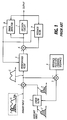
- a prior art interference canceller includes primary and auxiliary antenna systems. As shown in Fig. 1, an input signal from the primary antenna system is applied to a subtractor 1. The primary input contains a desired signal S and a wideband interference component J , both of which are affected by multipath distortions. An input signal J' from the auxiliary antenna is filtered by an adaptive linear transversal filter 2 and subtracted from the primary input by subtractor 1, whose output is coupled to a subtractor 3 where it is subtracted from a training sequence supplied from a reference pulse generator 4. The training sequence is a series of pulses that occur at the same rate as burst signals that appear at periodic intervals in the desired signal.
- the subtractors 1, 3, the linear filter 2 and the reference pulse generator 4 constitute a circuit known as an adaptive noise canceller and a detailed description of the canceller is given in "Adaptive Signal Processing" by Bernard Widrow and Samual D. Stearns, Prentice-Hall, Inc, 1985.
- Signals J and J' are considered as different versions of the same signal transmitted from a common undesired source as they have travelled over different propagation paths and therefore affected by different channel impulse response characteristics.
- the tap-gain coefficients of linear transversal filter 2 are constantly updated with the output of subtractor 3 according to the least mean square (LMS) algorithm and the filter output is applied to subtractor 1 as an estimate of the wideband interference J .
- LMS least mean square
- a decision feedback equalizer comprising a feedforward filter 5, a subtractor 6, a decision circuit 7, an error detector 8 and a feedback transversal filter 9, where it is adaptively equalized to remove intersymbol interference caused by multipath fading.
- the operation of the prior art interference canceller is satisfactory only when the auxiliary input does not contain a component of the desired signal. If a desired component is contained in the auxiliary input, it would cause an additional multipath distortion or a reduction of the desired signal of the primary input by mutual cancellation.
- Due to the use of a linear transversal filter for filtering the auxiliary input receiver noises are distributed along the taps of the linear filter and are mixed with the primary input and the amplification of the noises prevents its tap-gain coefficients from converging to a value sufficient to provide interference cancellation.
- the use of the trailing sequence at burst intervals prevents high speed updating of the tap gain coefficients if the multipath fading of an interference signal varies at a rate higher than the rate at which the training sequence is generated.
- the object of the present invention is obtained by detecting an interference signal transmitted from an undesired source by taking the difference between a received signal and a replica of the desired signal.
- a feedforward equalizer operates on a signal received by an antenna and produces an equalized feedforward output signal.
- the feedforward equalizer comprises (N - 1) delay-line elements connected in series to define N delay-line taps for producing successively delayed versions of the received signal at the N delay-line taps, N multipliers for operating on the delayed signals at the delay-line taps, N correlators responsive to a first error control signal for modifying signals at the delay-line taps for respectively supplying tap-gain signals to the multipliers, summing means for combining outputs from the N multipliers into the equalized feedforward output signal, and means for nullifying the outputs of (N - 1) ones of the N multipliers in response to the gate control signal.
- a data recovery, or decision circuit makes a decision on an equalized desired signal to recover the transmitted data.
- First and second feedback equalizers are provided.
- the first feedback equalizer operates on decision output signals from the data recovery circuit in accordance with the first error control signal and the second feedback (replica filter) equalizer nonlinearly filters decision output signals from the data recovery circuit in accordance with a second error control signal and generate an estimate of a desired component of the equalized feedforward output signal.
- a first combiner combines outputs from the second feedback equalizer and the feedforward equalizer to supply an estimate of an undesired component of the equalized feedforward output signal to the second feedback equalizer as the second error control signal.
- a second combiner combines outputs from the first combiner, the feedforward equalizer and the first feedback equalizer to produce a signal corresponding to the equalized desired signal for the data recovery circuit.
- An error detector is responsive to a difference between the outputs of the second combiner and the data recovery circuit for generating the first error control signal for the feedforward equalizer and the first feedback equalizer.
- a gate circuit is provided for establishing a connection between the output of the first combiner and an input of the second combiner in response to the presence of the gate control signal and clearing the connection in response to the absence of the gate control signal.
- the canceller of the present invention operates to cancel minimum phase shift fading distortions and interference distortions, and in the absence of the interference, the canceller operates to cancel non-minimum phase shift fading distortions as well as minimum phase shift fading distortions.
- the first feedback equalizer comprises N delay-line elements connected in series to the output of the data recovery circuit to define N delay-line taps at the outputs of the N delay-line elements for producing N successively delayed versions of the decision output signal, N multipliers for operating on the delayed decision output signals at the N delay-line taps, N correlators responsive to the first error control signal for updating tap-gain coefficients supplied to the N multipliers, and a summing circuit for combining outputs from the N multipliers into a signal for coupling to the second combiner.
- the second feedback equalizer comprises N delay-line elements connected in series to the output of the data recovery circuit to define (N + 1) delay-line taps for producing (N + 1) successively delayed versions of the decision output signal at the (N + 1) delay-line taps, (N + 1) multipliers for operating on the delayed decision output signals at the (N + 1) delay-line taps, (N + 1) correlators responsive to the second error control signal for modifying signals at the (N + 1) delay-line taps for respectively supplying tap-gain signals to the (N + 1) multipliers, and a summing circuit for combining outputs from the (N + 1) multipliers into a signal for coupling to the first combiner.
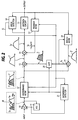
- the interference canceller of the present invention receives a QPSK modulated signal by a single antenna, not shown, and converted to an intermediate frequency signal which is amplified by an IF amplifier 10 whose amplification gain is controlled by an automatic gain control circuit 11.
- the IF signal is applied to a feedforward transversal filter 12 as a signal containing a desired signal S n and an interference signal J n . It should be noted that the interference canceller operates equally when the baseband of a transmitted signal is applied to the feedforward filter 12.
- the signal (symbol) is transmitted at sampling intervals T and affected by multipath fading and as a result the communication channel from the transmitter to the receiver has a particular channel impulse response as typically shown in Fig. 4.
- the channel response contains the dominant response h0 and delayed components h1, h2, and h3. No components preceding the dominant response H0 are contained since the channel response of long-span multipath fading channels has delayed components.
- the channel response can be approximated on a two-ray (path) propagation model. Therefore, the two-path model is usually used for approximating the effect of multipath fades on different components of a transmitted signal.
- phase shift fading In which the stronger, primary component of the signal arrives earlier than a weaker, secondary component, and the channel impulse response produce postcursors (previous pulses, i.e., samples to the right of reference sample).
- the other is termed a non-minimum phase shift fading in which the later-arriving, secondary component has a higher signal strength than the earlier-arriving component.
- the later-arriving component is treated as a primary signal and the earlier-arriving component as an advanced, secondary (undesired) signal, and the channel impulse response produces precursors (future pulses, i.e., samples to the left).
- the spectral components of the signal S n is affected to produce a spectral notch as indicated at 30 in Fig. 2. If the interference signal J from a different transmission source is also affected by multipath fading, a similar spectral notch may appear in the frequency spectrum of the interference signal.
- the feedforward filter 12 has a variable number of delay-line taps and operates in a multitap mode or a single tap mode. During a multitap mode, the feedforward filter 12 compensates for precursor distortion that arise when the communication channel is of non-minimum phase shift fading, and during a single tap mode it compensates for postcursors that arise when the communication channel is of minimum phase shift fading.
- Feedforward filter 12 produces an output signal S' + J' , which applied to the positive input of a subtractor 13 the negative input of which receives an interference estimate from a subtractor 19 via a gate circuit 20 to produce a replica S' of the desired signal.
- the output of subtractor 13 is connected to the positive input of a subtractor 14, the output of subtractor 14 being coupled to a data recovery, or decision circuit 15 where the original signal is recovered.
- a feedback transversal filter 17 is connected to the output of decision circuit 15 to compensate for postcursor distortion by supplying an error signal S e to the subtractor 14.
- the output of subtractor 14 is an equalized desired signal S d that is applied to a data recovery, or decision circuit 15 for recovering quantized data signals.
- the difference between the input and output of the decision circuit 15 is taken by an error detector 16 to produce an error signal ⁇ 1. This error signal is applied to the feedforward filter 12 and feedback filter 17 to adaptively update their tap-gain coefficients.
- a second feedback filter, or replica filter 18 of transversal structure is connected to the output of the decision circuit 15 for nonlinearly filtering the recovered output signal to produce an estimate ' of the desired signal S' appearing at the output of subtractor 13.
- the estimate ' is subtracted by subtractor 19 from the output signal S' + J' of the feedforward filter 12 to provide the interference estimate to subtractor 13 when the gate circuit 20 is closed.
- the output of subtractor 19 is further applied to replica filter 18 as an error signal ⁇ 2 to update its tap gain coefficients.
- an interference detector 21 which receives the gain control voltage of AGC 11 and the output of error detector 16 to detect the presence of an interfering signal, when the received signal level is high and, at the same time, a substantial amount of error is detected by error detector 16, and produces an interference detect signal. This signal is applied as a gate control signal to both gate circuit 20 and feedforward filter 12.
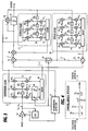
- feedforward filter 12 comprises complex delay-line units 401 and 402, each with unit delay time T, connected in series to the output of IF amplifier 10 to define three taps, complex multipliers or weighting devices 410, 411 and 412 for weighting the delayed tap signal samples at the taps of the delay-line 40 with tap-gain signals C 0 , C 1 and C 2 .
- These tap-gain signals are respectively derived from complex correlators 420, 421 and 422 by correlations between the error signal ⁇ 1 and the delayed tap signal samples.
- the output of multiplier 410 is delivered to an adder 43 and the outputs of multipliers 411 and 412 are coupled through a normally-closed gate circuit 44 to adder 43.
- Gate circuit 44 responds to the gate control signal from interference detector 21 by disconnecting the circuits between multipliers 411 and 412 and adder 43.
- the output of adder 43 is connected to the positive input of both subtractors 13 and 19.
- Feedback filter 17 is made up of complex delay-line units 501, 502 and 503 connected in series to the output of decision circuit 15, complex multipliers 511, 512 and 513 for weighting the delayed tap signal samples at the outputs of delay-line units 50 with tap-gain signals d 1 , d 2 and d 3 which are respectively derived from complex correlators 521, 522 and 523 by correlations between the error signal ⁇ 1 and the delayed tap signal samples.
- the output of multipliers 51 are delivered to an adder 53 whose output is coupled to the negative input of subtractor 14.
- Replica filter 18 includes complex delay-line units 601, 602 and 603 connected in series to the output of decision circuit 15 to define four successive taps, complex multipliers 610, 611, 612, and 613 for weighting the delayed tap signal samples at the taps of delay-line 60 with tap-gain signals w0, w1, w2 and w3 which are respectively derived from complex correlators 620, 621, 622 and 623 by correlations between the error signal ⁇ 2 and the delayed tap signal samples.
- the output of multipliers 61 are delivered to an adder 63 whose output is coupled to the negative input of subtractor 19.
- gate circuit 20 In the absence of an interference from an undesired signal source, gate circuit 20 is open and feedforward filter 12 is in a three-tap mode to compensate for precursors arising from non-minimum phase shift fading.
- the interference detector 21 In the presence of an interference from an undesired source, the interference detector 21 produces a gate signal, causing gate circuit 20 to establish a circuit between subtractors 19 and 13 and gate circuit 44 to nullify the outputs of complex multipliers 411 and 412.
- Feedforward filter 12 is thus switched to a single-tap mode in which its precursor-cancelling capability is reduced to a practically minimum level and the only active tap gain coefficient is c 0 .
- interference cancellation proceeds as follows to minimize the mean square value of the first error signal ⁇ 2 according to the LMS algorithm.
- the interference is first estimated by taking the difference between the replica filter 18 output and the feedforward filter 12 output by subtractor 19. The value of this estimate is then applied to subtractor 13 where the interference is cancelled, and the intersymbol interference caused by minimum phase shift fading (postcursor distortion) is finally eliminated by feedback filter 17.
- the desired symbol S i of the input signal of the feedforward filter 12 is given by: where, h i is the impulse response for a symbol a i of a transmitted symbol sequence ⁇ a n ⁇ and m is index of filter delay-line taps.
- h i is the impulse response for a symbol a i of a transmitted symbol sequence ⁇ a n ⁇ and m is index of filter delay-line taps.
- the recovered clock timing tends to deviate from the optimum timing and the received signal is impaired as if it were affected by precursors. Therefore, the feedforward filter 12 operates in a single-tap (practically minimum tap count) mode to cancel such precursors.
- the output of the filter 12 would appear as consisting of a desired symbol S' plus an interference component J' and the symbol at sample instant i is given as follows.
- the output of the replica filter 18 is represented as: If the relation i ⁇ a i holds, from Equations (2), (3) and (4), the error signal ⁇ 2 is obtained as follows:
- feedforward filter 12 could be operated in a three-tap mode in the presence of interference, it would produce an output containing a component contributed from convolution of symbols a +1 and a +2 that are transmitted after symbol a0 and precursors with tap-gain coefficients c 1 and c 2 .
- no symbols would appear at every tap of replica filter 18 corresponding to symbols a +1 and a +2 .
- a substantial amount of error between component S' and the symbol estimate ' would be fed into decision circuit 15.
- the transmission path may have non-minimum phase shift fading characteristic giving rise to precursors in the received signal which is also contaminated by an interference from an undesired signal source, a certain amount of such precursors may not be cancelled.
- the cancellation of both postcursors (minimum phase shift fading distortion) and wideband interference distortion with a minimum feedforward filter tap outweighs the loss of cancellation of some precursors.
- the present invention eliminates the need for an auxiliary antenna or a diversity antenna. Since only one antenna is used for cancelling interference, undesired cancellation of desired signals is avoided. Since the replica filter provides nonlinear filtering of recovered symbols, the undesired effect of noise enhancement is completely eliminated. Furthermore, the transmission efficiency can be improved by the elimination of training sequence.
Landscapes
- Engineering & Computer Science (AREA)
- Computer Networks & Wireless Communication (AREA)
- Signal Processing (AREA)
- Cable Transmission Systems, Equalization Of Radio And Reduction Of Echo (AREA)
- Noise Elimination (AREA)
Applications Claiming Priority (2)
| Application Number | Priority Date | Filing Date | Title |
|---|---|---|---|
| JP4089061A JP2762836B2 (ja) | 1992-04-09 | 1992-04-09 | 干渉波除去装置 |
| JP89061/92 | 1992-04-09 |
Publications (3)
| Publication Number | Publication Date |
|---|---|
| EP0565104A2 true EP0565104A2 (fr) | 1993-10-13 |
| EP0565104A3 EP0565104A3 (en) | 1993-12-08 |
| EP0565104B1 EP0565104B1 (fr) | 1998-01-07 |
Family
ID=13960343
Family Applications (1)
| Application Number | Title | Priority Date | Filing Date |
|---|---|---|---|
| EP93105821A Expired - Lifetime EP0565104B1 (fr) | 1992-04-09 | 1993-04-08 | Annuleur d'interférence avec un filtre transversal ayant de coefficients de prises commutés |
Country Status (4)
| Country | Link |
|---|---|
| US (1) | US5345476A (fr) |
| EP (1) | EP0565104B1 (fr) |
| JP (1) | JP2762836B2 (fr) |
| DE (1) | DE69316065T2 (fr) |
Cited By (7)
| Publication number | Priority date | Publication date | Assignee | Title |
|---|---|---|---|---|
| EP0680154A3 (fr) * | 1994-04-28 | 1996-07-24 | Nec Corp | Suppression d'interférence utilisant un système d'antennes adaptif à inversion de puissance et un égalisateur adaptif selon le procédé à erreur quadratique minimale. |
| EP0720334A3 (fr) * | 1994-12-26 | 1998-08-05 | Nec Corporation | Egaliseur à décision récursive, pour l'annulation des composantes multivoies courtes et longues, utilisant des symboles de décision retardés en correspondance |
| WO1998042089A3 (fr) * | 1997-03-14 | 1998-10-29 | At & T Corp | Egalisation spatio-temporelle pour systemes amrt is-136 a evanouissement dispersif rapide et brouillage dans un meme canal |
| WO2002045282A1 (fr) * | 2000-11-30 | 2002-06-06 | Alexandr Vasilievich Garmonov | Procede pour recevoir des signaux a voies multiples dans des systemes de communication radio a acces multiple par code de repartition et dispositif de mise en oeuvre de ce procede |
| EP1260025A2 (fr) * | 2000-02-24 | 2002-11-27 | Veridian Engineering, Inc. | Eliminateur d'interferences |
| EP3214760B1 (fr) * | 2016-03-01 | 2019-08-28 | MediaTek Inc. | Dispositif de filtrage à action directe et procédé associé |
| CN112564733A (zh) * | 2019-09-25 | 2021-03-26 | 瑞昱半导体股份有限公司 | 具射频干扰消除机制的电子系统及相关射频干扰消除方法 |
Families Citing this family (35)
| Publication number | Priority date | Publication date | Assignee | Title |
|---|---|---|---|---|
| US5517527A (en) * | 1992-12-11 | 1996-05-14 | Industrial Technology Research Institute | Adaptive equalizer for ISDN U-interface transceiver |
| US5513216A (en) * | 1994-10-13 | 1996-04-30 | At&T Corp. | Hybrid equalizer arrangement for use in data communications equipment |
| US5550596A (en) * | 1994-11-25 | 1996-08-27 | Thomson Multimedia Sa | Digital television signal processing system including a co-channel rejection filter |
| US5572262A (en) * | 1994-12-29 | 1996-11-05 | Philips Electronics North America Corporation | Receiver based methods and devices for combating co-channel NTSC interference in digital transmission |
| KR0162340B1 (ko) * | 1995-04-28 | 1998-12-01 | 구자홍 | 디지탈 통신 시스템의 고스트 제거 등화기 |
| FI98177C (fi) * | 1995-06-01 | 1997-04-25 | Nokia Mobile Phones Ltd | Menetelmä ja piirijärjestely häiriöllisen signaalin käsittelemiseksi |
| US5694437A (en) * | 1995-10-10 | 1997-12-02 | Motorola, Inc. | Device and method for data signal detection in the presence of distortion and interference in communication systems |
| US6233272B1 (en) | 1996-03-19 | 2001-05-15 | Yrp Mobile Telecommunications Key Technology Research Laboratories Co., Ltd. | Spread spectrum communication receiver |
| US5901173A (en) * | 1996-12-09 | 1999-05-04 | Raytheon Company | Noise Estimator |
| US6173021B1 (en) * | 1997-06-23 | 2001-01-09 | Paradyne Corporation | Method and apparatus for reducing interference in a twisted wire pair transmission system |
| US6330275B1 (en) | 1997-06-23 | 2001-12-11 | Paradyne Corporation | Method and apparatus for overcoming periodic disturbances in digital subscriber loops |
| US6285709B1 (en) * | 1997-10-31 | 2001-09-04 | 3 Com Corporation | Error filtering in a hybrid equalizer system |
| US6144697A (en) * | 1998-02-02 | 2000-11-07 | Purdue Research Foundation | Equalization techniques to reduce intersymbol interference |
| US6249518B1 (en) * | 1998-08-07 | 2001-06-19 | Nortel Networks Limited | TDMA single antenna co-channel interference cancellation |
| US6535554B1 (en) | 1998-11-17 | 2003-03-18 | Harris Corporation | PCS signal separation in a one dimensional channel |
| US6870881B1 (en) | 2000-08-24 | 2005-03-22 | Marvell International Ltd. | Feedforward equalizer for DFE based detector |
| US7010069B2 (en) * | 2000-12-04 | 2006-03-07 | Trellisware Technologies, Inc. | Method for co-channel interference identification and mitigation |
| US20020168972A1 (en) * | 2001-05-11 | 2002-11-14 | Justiss James E. | Antenna feedforward interference cancellation system |
| US20020181575A1 (en) * | 2001-05-29 | 2002-12-05 | Koninklijke Philips Electronics N.V. | Circuitry for Mitigating performance loss associated with feedback loop delay in decision feedback equalizer and method therefor |
| US7302023B2 (en) * | 2002-07-25 | 2007-11-27 | Yang George L | Application of multipath combiner and equalizer in a multi-channel direct sequence spread spectrum communication system |
| JP2005537747A (ja) * | 2002-08-30 | 2005-12-08 | コーニンクレッカ フィリップス エレクトロニクス エヌ ヴィ | 周波数領域判定フィードバック等化デバイス及び方法 |
| WO2005060655A2 (fr) * | 2003-12-16 | 2005-07-07 | California Institute Of Technology | Egaliseur de gigue deterministe |
| EP1929649A4 (fr) * | 2005-09-26 | 2012-06-13 | Lg Electronics Inc | Procede et dispositif de suppression des interferences |
| JP5084051B2 (ja) * | 2006-09-06 | 2012-11-28 | シャープ株式会社 | 送受信装置、送受信システムおよび送受信方法 |
| US8184686B2 (en) * | 2007-01-10 | 2012-05-22 | Cortina Systems, Inc. | System and method for recovering data received over a communication channel |
| US8406356B2 (en) | 2007-06-06 | 2013-03-26 | Micron Technology, Inc. | Self-calibrating continuous-time equalization |
| US8249540B1 (en) | 2008-08-07 | 2012-08-21 | Hypres, Inc. | Two stage radio frequency interference cancellation system and method |
| US8743940B1 (en) | 2010-01-07 | 2014-06-03 | Marvell International Ltd. | Method and apparatus for adaptively determining settings of a transmit equalizer |
| US8811464B1 (en) | 2010-01-21 | 2014-08-19 | Marvell International Ltd. | Method and apparatus for adaptively determining equalizer settings for 10GBASE-KR transmitter |
| US8548108B2 (en) * | 2011-02-14 | 2013-10-01 | Fujitsu Limited | Adaptive phase equalizer |
| US8891607B2 (en) | 2012-09-06 | 2014-11-18 | Avago Technologies General Ip (Singapore) Pte. Ltd. | Feed forward equalizer tap weight adaptation based on channel estimation |
| US8964827B2 (en) | 2013-03-07 | 2015-02-24 | Avago Technologies General Ip (Singapore) Pte. Ltd. | Adaptation of equalizer settings using error signals sampled at several different phases |
| WO2019048903A1 (fr) * | 2017-09-06 | 2019-03-14 | Telefonaktiebolaget Lm Ericsson (Publ) | Procédé et appareil d'étalonnage de réseau d'antennes avec réduction des interférences |
| US11184065B2 (en) | 2017-10-31 | 2021-11-23 | Telefonaktiebolaget Lm Ericsson (Publ) | Orthogonal training signals for transmission in an antenna array |
| US10826731B2 (en) * | 2018-09-28 | 2020-11-03 | Huawei Technologies Co., Ltd. | Efficient implementation of noise whitening post-compensation for narrowband-filtered signals |
Family Cites Families (5)
| Publication number | Priority date | Publication date | Assignee | Title |
|---|---|---|---|---|
| NL8700125A (nl) * | 1987-01-20 | 1988-08-16 | Philips Nv | Inrichting voor het bestrijden van intersymboolinterferentie en ruis. |
| NL8701333A (nl) * | 1987-06-09 | 1989-01-02 | Philips Nv | Inrichting voor het bestrijden van intersymboolinterferentie en ruis. |
| NL8701332A (nl) * | 1987-06-09 | 1989-01-02 | Philips Nv | Systeem voor transmissie van datasignalen met gebruikmaking van beslissingsteruggekoppelde egalisatie. |
| US5031194A (en) * | 1989-08-11 | 1991-07-09 | Bell Communications Research, Inc. | Wideband digital equalizers for subscriber loops |
| US5119401A (en) * | 1989-11-17 | 1992-06-02 | Nec Corporation | Decision feedback equalizer including forward part whose signal reference point is shiftable depending on channel response |
-
1992
- 1992-04-09 JP JP4089061A patent/JP2762836B2/ja not_active Expired - Fee Related
-
1993
- 1993-04-08 EP EP93105821A patent/EP0565104B1/fr not_active Expired - Lifetime
- 1993-04-08 DE DE69316065T patent/DE69316065T2/de not_active Expired - Fee Related
- 1993-04-09 US US08/045,555 patent/US5345476A/en not_active Expired - Fee Related
Cited By (10)
| Publication number | Priority date | Publication date | Assignee | Title |
|---|---|---|---|---|
| EP0680154A3 (fr) * | 1994-04-28 | 1996-07-24 | Nec Corp | Suppression d'interférence utilisant un système d'antennes adaptif à inversion de puissance et un égalisateur adaptif selon le procédé à erreur quadratique minimale. |
| EP0720334A3 (fr) * | 1994-12-26 | 1998-08-05 | Nec Corporation | Egaliseur à décision récursive, pour l'annulation des composantes multivoies courtes et longues, utilisant des symboles de décision retardés en correspondance |
| WO1998042089A3 (fr) * | 1997-03-14 | 1998-10-29 | At & T Corp | Egalisation spatio-temporelle pour systemes amrt is-136 a evanouissement dispersif rapide et brouillage dans un meme canal |
| EP1260025A2 (fr) * | 2000-02-24 | 2002-11-27 | Veridian Engineering, Inc. | Eliminateur d'interferences |
| WO2002045282A1 (fr) * | 2000-11-30 | 2002-06-06 | Alexandr Vasilievich Garmonov | Procede pour recevoir des signaux a voies multiples dans des systemes de communication radio a acces multiple par code de repartition et dispositif de mise en oeuvre de ce procede |
| GB2385760A (en) * | 2000-11-30 | 2003-08-27 | Alexandr Vasilievich Garmonov | Method for receiving multipath signals in a radio communications system with a code division multiple access and device for carrying out said method |
| GB2385760B (en) * | 2000-11-30 | 2004-03-24 | Alexandr Vasilievich Garmonov | Method and device of multipath signal reception in CDMA system |
| US7103375B2 (en) | 2000-11-30 | 2006-09-05 | Alexandr Vasilievich Garmonov | Method for receiving multipath signals in a radio communications system with a code division multiple access and device for carrying out said method |
| EP3214760B1 (fr) * | 2016-03-01 | 2019-08-28 | MediaTek Inc. | Dispositif de filtrage à action directe et procédé associé |
| CN112564733A (zh) * | 2019-09-25 | 2021-03-26 | 瑞昱半导体股份有限公司 | 具射频干扰消除机制的电子系统及相关射频干扰消除方法 |
Also Published As
| Publication number | Publication date |
|---|---|
| EP0565104A3 (en) | 1993-12-08 |
| DE69316065D1 (de) | 1998-02-12 |
| JPH05291972A (ja) | 1993-11-05 |
| DE69316065T2 (de) | 1998-08-27 |
| JP2762836B2 (ja) | 1998-06-04 |
| EP0565104B1 (fr) | 1998-01-07 |
| US5345476A (en) | 1994-09-06 |
Similar Documents
| Publication | Publication Date | Title |
|---|---|---|
| EP0565104B1 (fr) | Annuleur d'interférence avec un filtre transversal ayant de coefficients de prises commutés | |
| US5349609A (en) | Adaptive interference cancellation and equalization using equalizer decision error as a common corrective factor | |
| US5692018A (en) | Time-diversity interference canceler with add/subtract/select circuit responsive to decision error | |
| US6751255B1 (en) | Decision feedback analyzer with filter compensation | |
| Qureshi | Adaptive equalization | |
| EP0720334B1 (fr) | Egaliseur à décision récursive, pour l'annulation des composantes multivoies courtes et longues, utilisant des symboles de décision retardés en correspondance | |
| US5524125A (en) | Interference cancellation apparatus capable of adaptive equalization and interference cancellation at a high speed on fading diversity channels | |
| US5031194A (en) | Wideband digital equalizers for subscriber loops | |
| US5539774A (en) | Dual decision equalization method and device | |
| US5119401A (en) | Decision feedback equalizer including forward part whose signal reference point is shiftable depending on channel response | |
| US5524023A (en) | Interference cancellation using power-inversion adaptive array and LMS adaptive equalizer | |
| US4328585A (en) | Fast adapting fading channel equalizer | |
| US7120193B2 (en) | Decision feedback equalizer with dynamic feedback control | |
| US20020150155A1 (en) | Convergence speed, lowering the excess noise and power consumption of equalizers | |
| US5335359A (en) | Diversity receiver using matched filter and decision feedback equalizer | |
| AU739837B2 (en) | A data transmission/reception unit | |
| US5398259A (en) | Decision-feedback equalizer for cancelling CW interference | |
| US7039104B2 (en) | Adaptive coefficient signal generator for adaptive signal equalizers with fractionally-spaced feedback | |
| EP0276511B1 (fr) | Filtre adaptatif en temps discret pour former un signal d'annulation de symboles synchrones de données | |
| US4982428A (en) | Arrangement for canceling interference in transmission systems | |
| US5440583A (en) | Decision feedback equalizer with second-order recursive filter controlled with two feedback coefficients | |
| US6940898B2 (en) | Adaptive coefficient signal generator for adaptive signal equalizers with fractionally-spaced feedback | |
| KR100202944B1 (ko) | 에러 궤환을 이용한 결정 궤환 등화기 | |
| JPH0744515B2 (ja) | 干渉波除去方式 | |
| JPH0435547A (ja) | 干渉波除去装置 |
Legal Events
| Date | Code | Title | Description |
|---|---|---|---|
| PUAI | Public reference made under article 153(3) epc to a published international application that has entered the european phase |
Free format text: ORIGINAL CODE: 0009012 |
|
| AK | Designated contracting states |
Kind code of ref document: A2 Designated state(s): DE FR GB IT |
|
| PUAL | Search report despatched |
Free format text: ORIGINAL CODE: 0009013 |
|
| AK | Designated contracting states |
Kind code of ref document: A3 Designated state(s): DE FR GB IT |
|
| 17P | Request for examination filed |
Effective date: 19931111 |
|
| GRAG | Despatch of communication of intention to grant |
Free format text: ORIGINAL CODE: EPIDOS AGRA |
|
| 17Q | First examination report despatched |
Effective date: 19961216 |
|
| GRAG | Despatch of communication of intention to grant |
Free format text: ORIGINAL CODE: EPIDOS AGRA |
|
| GRAG | Despatch of communication of intention to grant |
Free format text: ORIGINAL CODE: EPIDOS AGRA |
|
| GRAH | Despatch of communication of intention to grant a patent |
Free format text: ORIGINAL CODE: EPIDOS IGRA |
|
| GRAH | Despatch of communication of intention to grant a patent |
Free format text: ORIGINAL CODE: EPIDOS IGRA |
|
| GRAA | (expected) grant |
Free format text: ORIGINAL CODE: 0009210 |
|
| AK | Designated contracting states |
Kind code of ref document: B1 Designated state(s): DE FR GB IT |
|
| REF | Corresponds to: |
Ref document number: 69316065 Country of ref document: DE Date of ref document: 19980212 |
|
| ITF | It: translation for a ep patent filed | ||
| ET | Fr: translation filed | ||
| PLBE | No opposition filed within time limit |
Free format text: ORIGINAL CODE: 0009261 |
|
| 26N | No opposition filed | ||
| REG | Reference to a national code |
Ref country code: GB Ref legal event code: IF02 |
|
| PGFP | Annual fee paid to national office [announced via postgrant information from national office to epo] |
Ref country code: GB Payment date: 20030402 Year of fee payment: 11 |
|
| PGFP | Annual fee paid to national office [announced via postgrant information from national office to epo] |
Ref country code: FR Payment date: 20030408 Year of fee payment: 11 |
|
| PGFP | Annual fee paid to national office [announced via postgrant information from national office to epo] |
Ref country code: DE Payment date: 20030417 Year of fee payment: 11 |
|
| PG25 | Lapsed in a contracting state [announced via postgrant information from national office to epo] |
Ref country code: GB Free format text: LAPSE BECAUSE OF NON-PAYMENT OF DUE FEES Effective date: 20040408 |
|
| PG25 | Lapsed in a contracting state [announced via postgrant information from national office to epo] |
Ref country code: DE Free format text: LAPSE BECAUSE OF NON-PAYMENT OF DUE FEES Effective date: 20041103 |
|
| GBPC | Gb: european patent ceased through non-payment of renewal fee |
Effective date: 20040408 |
|
| PG25 | Lapsed in a contracting state [announced via postgrant information from national office to epo] |
Ref country code: FR Free format text: LAPSE BECAUSE OF NON-PAYMENT OF DUE FEES Effective date: 20041231 |
|
| REG | Reference to a national code |
Ref country code: FR Ref legal event code: ST |
|
| PG25 | Lapsed in a contracting state [announced via postgrant information from national office to epo] |
Ref country code: IT Free format text: LAPSE BECAUSE OF NON-PAYMENT OF DUE FEES;WARNING: LAPSES OF ITALIAN PATENTS WITH EFFECTIVE DATE BEFORE 2007 MAY HAVE OCCURRED AT ANY TIME BEFORE 2007. THE CORRECT EFFECTIVE DATE MAY BE DIFFERENT FROM THE ONE RECORDED. Effective date: 20050408 |