EP0565330B1 - Procédé et cellule d'électrolyse pour la production de fluor - Google Patents
Procédé et cellule d'électrolyse pour la production de fluor Download PDFInfo
- Publication number
- EP0565330B1 EP0565330B1 EP93302660A EP93302660A EP0565330B1 EP 0565330 B1 EP0565330 B1 EP 0565330B1 EP 93302660 A EP93302660 A EP 93302660A EP 93302660 A EP93302660 A EP 93302660A EP 0565330 B1 EP0565330 B1 EP 0565330B1
- Authority
- EP
- European Patent Office
- Prior art keywords
- anode
- cathode
- cell
- fluorine
- electrolyte
- Prior art date
- Legal status (The legal status is an assumption and is not a legal conclusion. Google has not performed a legal analysis and makes no representation as to the accuracy of the status listed.)
- Expired - Lifetime
Links
- 239000011737 fluorine Substances 0.000 title claims description 55
- 229910052731 fluorine Inorganic materials 0.000 title claims description 55
- 238000000034 method Methods 0.000 title claims description 17
- 238000004519 manufacturing process Methods 0.000 title claims description 9
- PXGOKWXKJXAPGV-UHFFFAOYSA-N Fluorine Chemical compound FF PXGOKWXKJXAPGV-UHFFFAOYSA-N 0.000 title 1
- 239000003792 electrolyte Substances 0.000 claims description 62
- YCKRFDGAMUMZLT-UHFFFAOYSA-N Fluorine atom Chemical compound [F] YCKRFDGAMUMZLT-UHFFFAOYSA-N 0.000 claims description 54
- 239000001257 hydrogen Substances 0.000 claims description 30
- 229910052739 hydrogen Inorganic materials 0.000 claims description 30
- UFHFLCQGNIYNRP-UHFFFAOYSA-N Hydrogen Chemical compound [H][H] UFHFLCQGNIYNRP-UHFFFAOYSA-N 0.000 claims description 28
- 230000001939 inductive effect Effects 0.000 claims description 5
- 239000007789 gas Substances 0.000 description 19
- 238000013461 design Methods 0.000 description 16
- OKTJSMMVPCPJKN-UHFFFAOYSA-N Carbon Chemical compound [C] OKTJSMMVPCPJKN-UHFFFAOYSA-N 0.000 description 5
- 229910052799 carbon Inorganic materials 0.000 description 5
- 229920002313 fluoropolymer Polymers 0.000 description 5
- 239000000047 product Substances 0.000 description 5
- 229910000831 Steel Inorganic materials 0.000 description 4
- 230000000694 effects Effects 0.000 description 4
- 239000010959 steel Substances 0.000 description 4
- 230000005587 bubbling Effects 0.000 description 3
- 238000005260 corrosion Methods 0.000 description 3
- 230000007797 corrosion Effects 0.000 description 3
- 239000002245 particle Substances 0.000 description 3
- 238000005215 recombination Methods 0.000 description 3
- 230000006798 recombination Effects 0.000 description 3
- XLYOFNOQVPJJNP-UHFFFAOYSA-N water Substances O XLYOFNOQVPJJNP-UHFFFAOYSA-N 0.000 description 3
- IJGRMHOSHXDMSA-UHFFFAOYSA-N Atomic nitrogen Chemical compound N#N IJGRMHOSHXDMSA-UHFFFAOYSA-N 0.000 description 2
- PXHVJJICTQNCMI-UHFFFAOYSA-N Nickel Chemical compound [Ni] PXHVJJICTQNCMI-UHFFFAOYSA-N 0.000 description 2
- 230000015572 biosynthetic process Effects 0.000 description 2
- 238000006243 chemical reaction Methods 0.000 description 2
- 238000001816 cooling Methods 0.000 description 2
- 238000006056 electrooxidation reaction Methods 0.000 description 2
- 150000002431 hydrogen Chemical class 0.000 description 2
- 230000002706 hydrostatic effect Effects 0.000 description 2
- 238000012423 maintenance Methods 0.000 description 2
- 239000000463 material Substances 0.000 description 2
- 229920000642 polymer Polymers 0.000 description 2
- 239000004810 polytetrafluoroethylene Substances 0.000 description 2
- 229920001343 polytetrafluoroethylene Polymers 0.000 description 2
- 239000007787 solid Substances 0.000 description 2
- TXEYQDLBPFQVAA-UHFFFAOYSA-N tetrafluoromethane Chemical compound FC(F)(F)F TXEYQDLBPFQVAA-UHFFFAOYSA-N 0.000 description 2
- 238000012546 transfer Methods 0.000 description 2
- ZAMOUSCENKQFHK-UHFFFAOYSA-N Chlorine atom Chemical compound [Cl] ZAMOUSCENKQFHK-UHFFFAOYSA-N 0.000 description 1
- KRHYYFGTRYWZRS-UHFFFAOYSA-N Fluorane Chemical compound F KRHYYFGTRYWZRS-UHFFFAOYSA-N 0.000 description 1
- 229910000792 Monel Inorganic materials 0.000 description 1
- 239000004698 Polyethylene Substances 0.000 description 1
- 239000000443 aerosol Substances 0.000 description 1
- 239000010406 cathode material Substances 0.000 description 1
- 238000003889 chemical engineering Methods 0.000 description 1
- 239000000460 chlorine Substances 0.000 description 1
- 229910052801 chlorine Inorganic materials 0.000 description 1
- 150000001875 compounds Chemical class 0.000 description 1
- 238000011161 development Methods 0.000 description 1
- 238000005868 electrolysis reaction Methods 0.000 description 1
- 238000005516 engineering process Methods 0.000 description 1
- 230000003628 erosive effect Effects 0.000 description 1
- 238000004880 explosion Methods 0.000 description 1
- 239000000706 filtrate Substances 0.000 description 1
- 238000010438 heat treatment Methods 0.000 description 1
- 229910000040 hydrogen fluoride Inorganic materials 0.000 description 1
- 239000000411 inducer Substances 0.000 description 1
- 230000000670 limiting effect Effects 0.000 description 1
- 239000012528 membrane Substances 0.000 description 1
- 229910052759 nickel Inorganic materials 0.000 description 1
- 229910052757 nitrogen Inorganic materials 0.000 description 1
- 239000004033 plastic Substances 0.000 description 1
- 229920003023 plastic Polymers 0.000 description 1
- -1 polyethylene Polymers 0.000 description 1
- 229920000573 polyethylene Polymers 0.000 description 1
- 229920006254 polymer film Polymers 0.000 description 1
- POHFBTRVASILTB-UHFFFAOYSA-M potassium;fluoride;dihydrofluoride Chemical compound F.F.[F-].[K+] POHFBTRVASILTB-UHFFFAOYSA-M 0.000 description 1
- 238000000926 separation method Methods 0.000 description 1
Images


Classifications
-
- C—CHEMISTRY; METALLURGY
- C25—ELECTROLYTIC OR ELECTROPHORETIC PROCESSES; APPARATUS THEREFOR
- C25B—ELECTROLYTIC OR ELECTROPHORETIC PROCESSES FOR THE PRODUCTION OF COMPOUNDS OR NON-METALS; APPARATUS THEREFOR
- C25B1/00—Electrolytic production of inorganic compounds or non-metals
- C25B1/01—Products
- C25B1/24—Halogens or compounds thereof
- C25B1/245—Fluorine; Compounds thereof
Definitions
- This invention relates to a process and to an electrolytic cell for the production of fluorine.
- the space/time yield for fluorine is inherently low due to the poor ratio of unscreened anode area to cell volume.
- the thickness of the anodes (>30mm), and the large anode and cathode gap mentioned above compound the problem.
- the end result is that an electrolytic plant for the production of modest quantities of fluorine occupies a vast area (compared with analogues such as chlorine).
- Anode failures are well known to those "skilled in the art", such failures including: “Polarisation” (the development of an unusually high anode overvoltage), anode breakage, failure of the electrical connections, and burning in fluorine.
- the fluorine off-gas pressure can be no greater than the hydrostatic head provided by the submerged gas separating skirts when the evolved hydrogen off-gas pressure is at atmospheric pressure. In practice this effectively limits the evolved fluorine pressure to a maximum of approximately 10cm water gauge. Operation above this pressure is theoretically possible if the hydrogen and fluorine pressures are kept in perfect balance, but a sudden failure of an external seal or joint could then result in a fluorine/hydrogen explosion within the electrolytic cell.
- US-A-4950370 discloses an electrolyte cell for fluorine generation.
- the cell is provided with a separator in the form of a membrane (such as perfluorinated polyethylene) along the length of the electrode to maintain the separation of the gases.
- a separator in the form of a membrane (such as perfluorinated polyethylene) along the length of the electrode to maintain the separation of the gases.
- Equally FR-A-2368550 and EP-A-150285 describe fluorine generating electrolyte cells again with gas separators.
- a process for the production of fluorine comprising the steps of passing a single stream of fluorine-containing electrolyte in non-turbulent flow between an anode and a cathode of an electrolytic cell, dividing the single stream of electrolyte emerging from between the anode and the cathode into two streams, one said stream emerging adjacent to the anode having fluorine entrained therein, and the other said stream emerging adjacent to the cathode having hydrogen entrained therein, and subsequently separating the fluorine and the hydrogen from the respective said streams, characterised in that the cell is without a separator extending the length of the cell between the anode and the cathode.
- an electrolytic cell for the production of fluorine comprises an anode and a cathode in relatively close juxtaposition, means for inducing a single stream of electrolyte to pass in non-turbulent flow between the anode and the cathode, and means for dividing the single stream of electrolyte emerging from between the anode and the cathode into two streams, one said stream emerging adjacent to the anode and the other said stream emerging adjacent to the cathode characterised in that the cell is without a separator extending the length of the cell between the anode and the cathode.
- the anode and the cathode have flat surfaces in parallel opposing relationship, and said flat surfaces desirably define a gap of 20mm or less.
- the inducing means may include a foraminuous element, or baffles, or a plurality of channels (eg a bundle to tubes), and or parallel plates located at an entry to the space between the anode and the cathode.
- the non-turbulent flow is streamline flow, or laminar flow, and desirably the flow is at a Reynold's Number of less 2000, eg 500.
- the flow conditions are selected to constrain the fluorine and hydrogen produced to flow substantially adjacent to the anode and the cathode respectively.
- the dividing means may comprise a knife-edged flow divider, and may be located mid-way between the anode and the cathode.
- the flow divider may be located in offset-relationship between the anode and the cathode, preferably offset towards the anode to increase the volume of the stream containing the hydrogen.
- the electrolytic cell of the invention may be incorporated in a system in which disengagement of the fluorine and hydrogen from their respective streams can be performed by means of separate vessels that may also serve to cool and filter the electrolyte.
- the two streams of gas-free electrolyte from the disengagement vessels may then be combined and recycled to the electrolytic cell inlet.
- the hydrogen fluoride in the electrolyte consumed during the electrolysis can be replaced by continuous addition to the streams at any stage after they have left the electrolytic cell.
- the effect achieved by the invention is that most of the fluorine evolved at the anode slides up the surface of the anode. Although some of the fluorine will break away from the surface of the anode, the fluorine should remain in close proximity to the anode surface as it flows upwardly in the stream of the electrolyte.
- the hydrogen evolved at the surface of the cathode does break away from the cathode surface, but it should still remain close to the cathode surface as it rises upwardly in the stream of electrolyte. In this way the product gases are inhibited from meeting and recombining despite the anode and cathode surfaces being in close juxtaposition.
- the single stream of electrolyte in the cell containing both hydrogen and fluorine is then split into two streams, one stream containing the greater part of the hydrogen and the other stream containing the greater part of the fluorine.
- FIG. 1 the system shown comprises an electrolytic cell unit 10 having outlet ducts 12, 14 connected to a fluorine disengagement section 16 and a hydrogen disengagement section 18 respectively of conventional designs.
- the sections 16, 18 have gas outlets 22, 24, and have bottom discharge ducts 26, 28 with non-return valves 27, 29 respectively, the ducts 26, 28 being joined to a common duct 30 leading to a filter unit 32.
- the filter unit 32 has a bottom discharge duct 34 connected to a cooler 36 which discharges to a dosing tank 38 having a feed inlet 40.
- the tank 38 has a discharge duct 42 connected to a pump 44 which is connected by a duct 45 to discharge to the cell unit 10.
- the cell unit 10 shown comprises a vessel 46 which may be of fluoroplastic material (eg PTFE) or plastic polymer coated steel, and has a base 47, sides 48, and a roof 49.
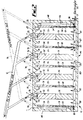
- a bank of eight electrolytic cells 50 are disposed in parallel in the vessel 46, each cell 50 having a carbon anode 52 and a steel cathode 54 each of plate form and in parallel opposing relationship to define a relatively narrow space 55, adjacent cells 50 sharing a common anode 52 or cathode 54.
- the lower portion of each anode 52 and cathode 54 is joined to a fluoroplastic (eg PTFE) portion 56, 58 respectively of the same cross-sectional dimensions as the respective anode 52 or cathode 54.
- a fluoroplastic (eg PTFE) portion 56, 58 respectively of the same cross-sectional dimensions as the respective anode 52 or cathode 54.
- a foraminuous member in the form of a steel sieve plate 60 extends parallel to the base 47 at the bottom of the fluoroplastic portions 56, 58.
- Cathodic electrical connections 64 are made to the sieve plate 60 at locations 66 at each side 48 of the vessel 46, and electrical connections 68 extend between each cathode 54 and the sieve plate 60 through the fluoroplastic portions 58.
- Anodic electric connections are made to each anode 52 at 70.
- An entry port 72 for electrolyte from the duct 45 of Figure 1 (not shown) is provided at one side 48 of the vessel 46 below the sieve plate 60.
- the roof 49 of the vessel 46 is shaped to form vee-shaped flow dividers 74 extending from mid-way between each anode 52 and cathode 54 so as to split electrolyte flowing upwardly between adjacent anodes 52 and cathodes 54 into two streams, each stream being diverted into a respective duct 76, 78 (shown in broken line) joined to the outlet ducts 12, 14 respectively of Figure 1.
- the pump 44 In operation with KF. 2HF electrolyte at about 100°C, the pump 44 circulates the electrolyte through the system of Figure 1. Electrolyte enters the vessel 46 of Figure 2 through the port 72 and passes through the sieve plate 60 into the spaces 55. The flow of the electrolyte is controlled so as to be non-turbulent, a Reynolds Number below 2000 being preferred, the sieve plate 60 and the fluoroplastic portions 56, 58 assisting in inducing this non-turbulent flow of the electrolyte. The known chemical reaction occurs in each cell 50, viz: 2HF ⁇ F 2 + H 2
- the fluorine liberated is entrained as bubbles 82 (see Figure 3) in that portion of the electrolyte flowing over the anodes 52, and into the ducts 76, whilst the hydrogen liberated is entrained as bubbles 84 in that portion of the electrolyte flowing over the cathodes 54 and into the ducts 78.
- the fluorine is disengaged at the section 16 by known methods whilst hydrogen is disengaged by known methods in the section 18.
- Electrolyte residues from the sections 16, 18 flow to the filter unit 32 for the removal of abrasive solids (eg carbon particles) which would otherwise cause erosion of the system.
- the electrolyte filtrate from the filter unit 32 passes to the cooler 36 to maintain the temperature of the electrolyte at about 100°C.
- the electrolyte is replenished with HF (eg from storage vessels) to maintain the concentration of HF in the electrolyte at about 45 v/o, the electrolyte then being circulated by the pump 44 into the cell unit 10.
- the fluorine and hydrogen entrained in the electrolyte may each comprise about 10 v/o, and when liberated at the sections 16, 18 may contain some HF - possibly between 15-20 v/o. This HF can be removed to a considerable extent (eg to less than 2 v/o) by known cryogenic techniques.
- the anode 52 and cathode 54 have an optimum spacing apart of about 20mm or less, eg 15mm. Additional flow inducers, for example adjacent parallel plates may be disposed in the cell unit 10 to constrain the non-turbulent flow conditions, for example between the portions 56, 58.
- the non-turbulent flow required may allow a flow rate of up to about 0.8m/sec of the electrolyte in the space 55, but 0.2m/sec is the optimum flow rate. It is desirable that the non-turbulent flow of the electrolyte commences between the portions 56, 58 before it reaches the anode 52 and the cathode 54.
- the direction of the flow of the electrolyte is designed to assist the removal of the fluorine and hydrogen from the space 55.
- the non-turbulent flow of the electrolyte allows a more narrow gap to be used between the anode and the cathode for a given level of product recombination than in current designs where turbulent flow patterns require a larger gap.
- the non-turbulent flow may be streamline flow or laminar flow, preferably below Reynold's Number 2000, for example 500.
- the cell unit 10 may be operated at a selected pressure to reduce the volume occupied by the fluorine and the hydrogen, for example at a pressure of about 15 psig or higher (eg 400 psi) as an alternative to a pressure of a few inches wg or some intermediate pressure.
- One advantage of the invention is that seals should not be necessary between adjacent cells 50 in the cell unit 10.
- the anode 52 and the cathode 54 may be located in slots in the vessel 46 to maintain control of the gap between opposing anodes 52 and cathodes 54.
- the flow dividers 74 may be positioned so as to divide the electrolyte into unequal streams, preferably with the stream adjacent to the cathode being the larger stream.
- FIG. 4 A preferred system incorporating an electrolytic cell of the invention is shown in Figure 4 to which reference is now made.
- the system 86 shown comprises an electrolytic cell 88 having an inlet duct 89 for electrolyte and outlet ducts 90, 91.
- the outlet duct 90 emerges from the anode region of the cell 88 and is joined to the lower portion of a disengagement vessel 92.
- the outlet duct 91 emerges from the cathode region of the cell 88 and is joined to the lower portion of a disengagement vessel 94.
- a return duct 96 connects the vessel 92 to the inlet duct 89, and a return duct 98 connects the vessel 94 to the inlet duct 89.
- the cell 88 is similar in many respects to the individual cells 50 of Figure 2 in having a space 100 between a flat anode 102 and a flat cathode 104.
- a flow-straightener 106 at the base of the space 100 constrains electrolyte to flow in non-turbulent flow through the space 100.
- the flow-straightener 106 defines a large number of evenly spaced channels 107 (eg about 3mm square) for flow of the electrolyte therethrough.
- a knife-edged flow divider 108 at the top of the space 100 diverts the electrolyte flowing in the space 100 into the outlet ducts 90, 91 respectively.
- Branch ducts 110, 111 connect with respective outlet ducts 90, 91.
- a carbon filter 112, 114 respectively is disposed near the base of each vessel 92, 94, and a gas outlet 116, 118 respectively is provided at the top of each vessel 92, 94.
- the cell 88 In operation with KF.2HF electrolyte at an operating potential of between 5.5 and 6.0 volts, the cell 88 operates in a similar manner to the cells 50 of Figure 2. Electrolyte flows from the inlet duct 89 through the channels 107 of the flow-straightener 106 into the space 100 where it is subsequently divided by the flow divider 108 to flow into the outlet ducts 90, 91 and the respective vessel 92, 94. The electrolyte occupies about one third of the height of each vessel 92, 94, fluorine being evolved in the vessel 92 and discharged through the outlet 116, and hydrogen being evolved in the vessel 94 and discharged through the outlet 118.
- the electrolyte flows into the respective return ducts 96, 98 to rejoin the inlet duct 89. Addition of nitrogen and HF can be made through the branch ducts 110, 111 as necessary.
- the evolution of bubbles of fluorine and hydrogen in the space 100 provides an "air-lift pump" effect on the electrolyte in the space 100 such that the system 86 should operate without the constant need for a pump to circulate the electrolyte.
- electrolytic cell of the invention may be incorporated in a suitable plate and frame design.
- FIG. 7 An example of a suitable disengagement vessel 92 is shown in Figure 7.
- the vessel 92 is cylindrical in longitudinal form, and has a weir plate 126 defining a gas bubbling space 127 and a bottom gap 128 through which electrolyte can pass to the carbon filter 114 held in a stub housing 130. Fluorine bubbling from the electrolyte flows towards the outlet 116.
- the size of the vessel 92 and the position of the weir plate 126 are selected so that electrolyte occupies about one third of the height of the vessel 92 which with the location of the gas bubbling space 127 minimises the risk of particles of electrolyte being carried towards the outlet 116.
- the vessel 94 may be of similar form.
- the design of the system 86 can be such that the inherently safe maximum off-gas pressure is that provided by the hydrostatic head between the base of the disengagement vessels 92, 94 and the lower point of the flow divider 108. This is the maximum operating pressure for which the reservoirs of fluorine and hydrogen will be kept apart in the event of a catastrophic failure of either a hydrogen or fluorine gas line. Since the disengagement vessels 92, 94 can be mounted several metres above the cell 88, this pressure equates to 5000cm water gauge or more, compared with 5-10cm for present cell designs.
Landscapes
- Chemical & Material Sciences (AREA)
- Inorganic Chemistry (AREA)
- Engineering & Computer Science (AREA)
- Chemical Kinetics & Catalysis (AREA)
- Electrochemistry (AREA)
- Materials Engineering (AREA)
- Metallurgy (AREA)
- Organic Chemistry (AREA)
- Electrolytic Production Of Non-Metals, Compounds, Apparatuses Therefor (AREA)
Claims (15)
- Procédé de production de fluor, le procédé comprenant les étapes consistant à passer un écoulement unique d'électrolyte contenant du fluor sous forme de flux non turbulent circulant entre une anode et une cathode d'une cellule électrolytique, à diviser l'écoulement unique d'électrolyte sortant entre l'anode et la cathode en deux écoulements, l'un desdits écoulements émergeant au voisinage de l'anode entraînant du fluor avec lui, et l'autre desdits écoulements émergeant au voisinage de la cathode entraînant de l'hydrogène avec lui, puis ensuite à séparer le fluor et l'hydrogène de leurs dits écoulements respectifs, caractérisé en ce que la cellule est sans séparateur s'étendant sur toute la longueur de la cellule, entre l'anode et la cathode.
- Cellule électrolytique destinée à être utilisée dans le procédé de production de fluor selon la revendication 1, la cellule comprenant une anode et une cathode juxtaposées de manière relativement rapprochée, des moyens pour induire un écoulement unique d'électrolyte sous forme de flux non turbulent circulant entre l'anode et la cathode, et des moyens pour diviser l'écoulement unique d'électrolyte sortant entre l'anode et la cathode en deux écoulements, l'un desdits écoulements émergeant au voisinage de l'anode et l'autre desdits écoulements émergeant au voisinage de la cathode, caractérisée en ce que la cellule est sans séparateur s'étendant sur toute la longueur de la cellule, entre l'anode et la cathode.
- Cellule électrolytique selon la revendication 2, et dans laquelle l'anode et la cathode ont des surfaces sensiblement planes opposées l'une à l'autre à la parallèle, et lesdites surfaces sensiblement planes définissant un espace de 20 mm ou moins.
- Cellule électrolytique selon la revendication 2, et dans laquelle les moyens d'induction de flux comprennent au moins un élément parmi un élément foramineux, des déflecteurs, une pluralité de canaux, et/ou des plaques parallèles, placé à une entrée de l'espace entre l'anode et la cathode.
- Cellule électrolytique selon la revendication 2, et dans laquelle les moyens de division comprennent un diviseur de flux situé sensiblement à mi-chemin entre l'anode et la cathode.
- Cellule électrolytique selon la revendication 2, et dans laquelle le diviseur de flux est situé avec un décalage entre l'anode et la cathode.
- Cellule électrolytique selon la revendication 6, et dans laquelle le diviseur de flux présente un décalage en direction de l'anode afin d'augmenter le volume de l'écoulement contenant l'hydrogène.
- Cellule électrolytique selon l'une quelconque des revendications 2 à 7, caractérisée en ce que la cellule est incorporée dans un système qui comprend des récipients séparés pour permettre, en utilisation, le dégagement du fluor et de l'hydrogène de leurs écoulements respectifs.
- Cellule électrolytique selon la revendication 8, et dans laquelle la cellule comprend une admission au niveau de laquelle, en utilisation, deux écoulements recombinés d'électrolyte débarrassé des gaz provenant des récipients de dégagement sont réadmis vers la cellule.
- Procédé selon la revendication 1, et dans lequel le flux non turbulent est un flux à écoulement sans tourbillonnement ou un flux à écoulement laminaire, et le flux se situe à un nombre de Reynolds de moins de 2000.
- Procédé selon la revendication 10, et dans lequel le flux se situe à un nombre de Reynolds situé entre 400 et 600.
- Procédé selon la revendication 10 ou la revendication 11, et dans lequel les conditions de flux sont choisies afin de forcer le fluor et l'hydrogène produits à s'écouler sensiblement au voisinage, respectivement, de l'anode et de la cathode.
- Procédé selon l'une quelconque des revendications 10 à 12, et dans lequel le flux non turbulent présente un débit allant jusqu'à environ 0,8 m/s de l'électrolyte entre les électrodes.
- Procédé selon l'une quelconque des revendications 10 à 13, et dans lequel le flux non turbulent de l'électrolyte débute avant qu'il n'atteigne l'anode et la cathode. 15.Procédé selon la revendication 1, et dans lequel on fait fonctionner la cellule à une pression choisie afin de réduire le volume occupé par le fluor et l'hydrogène.
Applications Claiming Priority (2)
| Application Number | Priority Date | Filing Date | Title |
|---|---|---|---|
| GB9207424 | 1992-04-04 | ||
| GB929207424A GB9207424D0 (en) | 1992-04-04 | 1992-04-04 | A process and an electrolytic cell for the production of fluorine |
Publications (2)
| Publication Number | Publication Date |
|---|---|
| EP0565330A1 EP0565330A1 (fr) | 1993-10-13 |
| EP0565330B1 true EP0565330B1 (fr) | 1997-07-09 |
Family
ID=10713483
Family Applications (1)
| Application Number | Title | Priority Date | Filing Date |
|---|---|---|---|
| EP93302660A Expired - Lifetime EP0565330B1 (fr) | 1992-04-04 | 1993-04-05 | Procédé et cellule d'électrolyse pour la production de fluor |
Country Status (8)
| Country | Link |
|---|---|
| US (1) | US5378324A (fr) |
| EP (1) | EP0565330B1 (fr) |
| JP (1) | JPH0673587A (fr) |
| CA (1) | CA2093299A1 (fr) |
| DE (1) | DE69311946T2 (fr) |
| ES (1) | ES2105107T3 (fr) |
| GB (1) | GB9207424D0 (fr) |
| ZA (1) | ZA932405B (fr) |
Cited By (1)
| Publication number | Priority date | Publication date | Assignee | Title |
|---|---|---|---|---|
| US6210549B1 (en) | 1998-11-13 | 2001-04-03 | Larry A. Tharp | Fluorine gas generation system |
Families Citing this family (17)
| Publication number | Priority date | Publication date | Assignee | Title |
|---|---|---|---|---|
| US20030010354A1 (en) * | 2000-03-27 | 2003-01-16 | Applied Materials, Inc. | Fluorine process for cleaning semiconductor process chamber |
| US6500356B2 (en) * | 2000-03-27 | 2002-12-31 | Applied Materials, Inc. | Selectively etching silicon using fluorine without plasma |
| US6843258B2 (en) * | 2000-12-19 | 2005-01-18 | Applied Materials, Inc. | On-site cleaning gas generation for process chamber cleaning |
| US20090001524A1 (en) * | 2001-11-26 | 2009-01-01 | Siegele Stephen H | Generation and distribution of a fluorine gas |
| US20030121796A1 (en) * | 2001-11-26 | 2003-07-03 | Siegele Stephen H | Generation and distribution of molecular fluorine within a fabrication facility |
| US20040037768A1 (en) * | 2001-11-26 | 2004-02-26 | Robert Jackson | Method and system for on-site generation and distribution of a process gas |
| US20040151656A1 (en) * | 2001-11-26 | 2004-08-05 | Siegele Stephen H. | Modular molecular halogen gas generation system |
| US6902629B2 (en) * | 2002-04-12 | 2005-06-07 | Applied Materials, Inc. | Method for cleaning a process chamber |
| US20050191225A1 (en) * | 2004-01-16 | 2005-09-01 | Hogle Richard A. | Methods and apparatus for disposal of hydrogen from fluorine generation, and fluorine generators including same |
| US20060054183A1 (en) * | 2004-08-27 | 2006-03-16 | Thomas Nowak | Method to reduce plasma damage during cleaning of semiconductor wafer processing chamber |
| US20060090773A1 (en) * | 2004-11-04 | 2006-05-04 | Applied Materials, Inc. | Sulfur hexafluoride remote plasma source clean |
| US20060266288A1 (en) * | 2005-05-27 | 2006-11-30 | Applied Materials, Inc. | High plasma utilization for remote plasma clean |
| JP5699576B2 (ja) * | 2010-12-08 | 2015-04-15 | ソニー株式会社 | 積層型微多孔膜、電池用セパレータおよび非水電解質電池 |
| US10907262B2 (en) | 2014-10-20 | 2021-02-02 | Ecole Polytechnique Federale De Lausanne (Epfl) | Membrane-less electrolyzer |
| JP6369489B2 (ja) * | 2016-02-26 | 2018-08-08 | コベルコ建機株式会社 | 作業機械 |
| CN111005032A (zh) * | 2019-12-26 | 2020-04-14 | 福建德尔科技有限公司 | 一种便携式全自动高纯氟气生产装置系统 |
| ES3061708T3 (en) * | 2022-06-03 | 2026-04-07 | Univ Antwerpen | Electrolysis reactor |
Family Cites Families (3)
| Publication number | Priority date | Publication date | Assignee | Title |
|---|---|---|---|---|
| GB1570004A (en) * | 1976-10-19 | 1980-06-25 | British Nuclear Fuels Ltd | Electrolytic production of fluorine |
| US4511440A (en) * | 1983-12-22 | 1985-04-16 | Allied Corporation | Process for the electrolytic production of fluorine and novel cell therefor |
| US4950370A (en) * | 1988-07-19 | 1990-08-21 | Liquid Air Corporation | Electrolytic gas generator |
-
1992
- 1992-04-04 GB GB929207424A patent/GB9207424D0/en active Pending
-
1993
- 1993-04-02 ZA ZA932405A patent/ZA932405B/xx unknown
- 1993-04-02 CA CA002093299A patent/CA2093299A1/fr not_active Abandoned
- 1993-04-02 US US08/042,263 patent/US5378324A/en not_active Expired - Fee Related
- 1993-04-02 JP JP5100235A patent/JPH0673587A/ja active Pending
- 1993-04-05 EP EP93302660A patent/EP0565330B1/fr not_active Expired - Lifetime
- 1993-04-05 DE DE69311946T patent/DE69311946T2/de not_active Expired - Fee Related
- 1993-04-05 ES ES93302660T patent/ES2105107T3/es not_active Expired - Lifetime
Cited By (1)
| Publication number | Priority date | Publication date | Assignee | Title |
|---|---|---|---|---|
| US6210549B1 (en) | 1998-11-13 | 2001-04-03 | Larry A. Tharp | Fluorine gas generation system |
Also Published As
| Publication number | Publication date |
|---|---|
| GB9207424D0 (en) | 1992-05-20 |
| EP0565330A1 (fr) | 1993-10-13 |
| JPH0673587A (ja) | 1994-03-15 |
| ES2105107T3 (es) | 1997-10-16 |
| CA2093299A1 (fr) | 1993-10-05 |
| DE69311946D1 (de) | 1997-08-14 |
| ZA932405B (en) | 1994-06-14 |
| US5378324A (en) | 1995-01-03 |
| DE69311946T2 (de) | 1998-02-26 |
Similar Documents
| Publication | Publication Date | Title |
|---|---|---|
| EP0565330B1 (fr) | Procédé et cellule d'électrolyse pour la production de fluor | |
| US4139447A (en) | Electrolyzer for industrial production of fluorine | |
| US6409895B1 (en) | Electrolytic cell and method for electrolysis | |
| EP0212240A1 (fr) | Dispositif pour l'électrolyse de solutions | |
| EP0582192A1 (fr) | Cellule bipolaire à passage et procédé électrochimique de fluoration | |
| HU183256B (en) | Bipolar diaphragm electrolyzer and bipolar cell | |
| US20070261954A1 (en) | Device for Producing Anodic Oxidaton Products of an Alkali or Alkali-Earth Metal Chloride Solution | |
| US3766044A (en) | Electrolytic cell system including upper and lower reacting chambers | |
| AU2001257097A1 (en) | Electrolytic cell and method for electrolysis | |
| US4950370A (en) | Electrolytic gas generator | |
| US4375400A (en) | Electrolyte circulation in an electrolytic cell | |
| JPS582275B2 (ja) | デンカイホウホウ オヨビ デンカイソウ | |
| US4372827A (en) | Novel horizontal diaphragmless electrolyzer | |
| US4236983A (en) | Process and apparatus for electrolysis of hydrochloric acid | |
| CA1041036A (fr) | Appareil electrochimique et mode de fabrication d'halogenures | |
| US3785951A (en) | Electrolyzer comprising diaphragmless cell spaces flowed through by the electrolyte | |
| US4059495A (en) | Method of electrolyte feeding and recirculation in an electrolysis cell | |
| US5296121A (en) | Target electrode for preventing corrosion in electrochemical cells | |
| US3450623A (en) | Electrolytic apparatus for the regeneration of chromium salt solutions | |
| US3180810A (en) | Electrolytic cell and method of operation | |
| US4725341A (en) | Process for performing HCl-membrane electrolysis | |
| US3203882A (en) | Method of operating an alkali chlorate cell | |
| US3463722A (en) | Electrolysis system for chlorate manufacture | |
| EP0039046B1 (fr) | Electrode pour cellules monopolaires de type filtre-presse et utilisation d'une telle électrode dans une cellule filtre-presse monopolaire | |
| CN1065104A (zh) | 从电解池中除去气-液混合物的设备 |
Legal Events
| Date | Code | Title | Description |
|---|---|---|---|
| PUAI | Public reference made under article 153(3) epc to a published international application that has entered the european phase |
Free format text: ORIGINAL CODE: 0009012 |
|
| AK | Designated contracting states |
Kind code of ref document: A1 Designated state(s): BE DE ES FR GB IT |
|
| 17P | Request for examination filed |
Effective date: 19931030 |
|
| 17Q | First examination report despatched |
Effective date: 19950517 |
|
| GRAG | Despatch of communication of intention to grant |
Free format text: ORIGINAL CODE: EPIDOS AGRA |
|
| GRAH | Despatch of communication of intention to grant a patent |
Free format text: ORIGINAL CODE: EPIDOS IGRA |
|
| GRAH | Despatch of communication of intention to grant a patent |
Free format text: ORIGINAL CODE: EPIDOS IGRA |
|
| GRAA | (expected) grant |
Free format text: ORIGINAL CODE: 0009210 |
|
| AK | Designated contracting states |
Kind code of ref document: B1 Designated state(s): BE DE ES FR GB IT |
|
| REF | Corresponds to: |
Ref document number: 69311946 Country of ref document: DE Date of ref document: 19970814 |
|
| ET | Fr: translation filed | ||
| REG | Reference to a national code |
Ref country code: ES Ref legal event code: FG2A Ref document number: 2105107 Country of ref document: ES Kind code of ref document: T3 |
|
| PLBE | No opposition filed within time limit |
Free format text: ORIGINAL CODE: 0009261 |
|
| STAA | Information on the status of an ep patent application or granted ep patent |
Free format text: STATUS: NO OPPOSITION FILED WITHIN TIME LIMIT |
|
| 26N | No opposition filed | ||
| PGFP | Annual fee paid to national office [announced via postgrant information from national office to epo] |
Ref country code: GB Payment date: 20000321 Year of fee payment: 8 |
|
| PGFP | Annual fee paid to national office [announced via postgrant information from national office to epo] |
Ref country code: FR Payment date: 20001009 Year of fee payment: 8 |
|
| PGFP | Annual fee paid to national office [announced via postgrant information from national office to epo] |
Ref country code: DE Payment date: 20001020 Year of fee payment: 8 |
|
| PGFP | Annual fee paid to national office [announced via postgrant information from national office to epo] |
Ref country code: ES Payment date: 20001030 Year of fee payment: 8 |
|
| PGFP | Annual fee paid to national office [announced via postgrant information from national office to epo] |
Ref country code: BE Payment date: 20001107 Year of fee payment: 8 |
|
| PG25 | Lapsed in a contracting state [announced via postgrant information from national office to epo] |
Ref country code: GB Free format text: LAPSE BECAUSE OF NON-PAYMENT OF DUE FEES Effective date: 20010405 |
|
| PG25 | Lapsed in a contracting state [announced via postgrant information from national office to epo] |
Ref country code: ES Free format text: LAPSE BECAUSE OF NON-PAYMENT OF DUE FEES Effective date: 20010406 |
|
| PG25 | Lapsed in a contracting state [announced via postgrant information from national office to epo] |
Ref country code: FR Free format text: THE PATENT HAS BEEN ANNULLED BY A DECISION OF A NATIONAL AUTHORITY Effective date: 20010430 Ref country code: BE Free format text: LAPSE BECAUSE OF NON-PAYMENT OF DUE FEES Effective date: 20010430 |
|
| BERE | Be: lapsed |
Owner name: BRITISH NUCLEAR FUELS P.L.C. Effective date: 20010430 |
|
| GBPC | Gb: european patent ceased through non-payment of renewal fee |
Effective date: 20010405 |
|
| PG25 | Lapsed in a contracting state [announced via postgrant information from national office to epo] |
Ref country code: DE Free format text: LAPSE BECAUSE OF NON-PAYMENT OF DUE FEES Effective date: 20020201 |
|
| REG | Reference to a national code |
Ref country code: FR Ref legal event code: ST |
|
| REG | Reference to a national code |
Ref country code: ES Ref legal event code: FD2A Effective date: 20030303 |
|
| PG25 | Lapsed in a contracting state [announced via postgrant information from national office to epo] |
Ref country code: IT Free format text: LAPSE BECAUSE OF NON-PAYMENT OF DUE FEES Effective date: 20050405 |