EP0565594B1 - Appareil servant a effectuer une analyse chimique seche de fluides - Google Patents
Appareil servant a effectuer une analyse chimique seche de fluides Download PDFInfo
- Publication number
- EP0565594B1 EP0565594B1 EP92902939A EP92902939A EP0565594B1 EP 0565594 B1 EP0565594 B1 EP 0565594B1 EP 92902939 A EP92902939 A EP 92902939A EP 92902939 A EP92902939 A EP 92902939A EP 0565594 B1 EP0565594 B1 EP 0565594B1
- Authority
- EP
- European Patent Office
- Prior art keywords
- filter
- base member
- retaining means
- depression
- mesh
- Prior art date
- Legal status (The legal status is an assumption and is not a legal conclusion. Google has not performed a legal analysis and makes no representation as to the accuracy of the status listed.)
- Expired - Lifetime
Links
- 239000000126 substance Substances 0.000 title claims abstract description 16
- 239000012530 fluid Substances 0.000 title claims abstract description 13
- 239000007788 liquid Substances 0.000 claims description 15
- 239000007787 solid Substances 0.000 claims description 15
- 239000003153 chemical reaction reagent Substances 0.000 claims description 10
- 239000000463 material Substances 0.000 claims description 6
- 239000004033 plastic Substances 0.000 claims description 6
- 229920003023 plastic Polymers 0.000 claims description 6
- 238000002347 injection Methods 0.000 claims description 4
- 239000007924 injection Substances 0.000 claims description 4
- 238000004891 communication Methods 0.000 claims description 2
- 238000009826 distribution Methods 0.000 claims description 2
- 210000004369 blood Anatomy 0.000 description 8
- 239000008280 blood Substances 0.000 description 8
- 239000004677 Nylon Substances 0.000 description 4
- 239000003365 glass fiber Substances 0.000 description 4
- 239000012528 membrane Substances 0.000 description 4
- 229920001778 nylon Polymers 0.000 description 4
- 230000000717 retained effect Effects 0.000 description 3
- 239000003292 glue Substances 0.000 description 2
- 230000001788 irregular Effects 0.000 description 2
- 239000011159 matrix material Substances 0.000 description 2
- 239000000243 solution Substances 0.000 description 2
- 239000000758 substrate Substances 0.000 description 2
- LFQSCWFLJHTTHZ-UHFFFAOYSA-N Ethanol Chemical compound CCO LFQSCWFLJHTTHZ-UHFFFAOYSA-N 0.000 description 1
- 239000004743 Polypropylene Substances 0.000 description 1
- 239000004793 Polystyrene Substances 0.000 description 1
- 239000002250 absorbent Substances 0.000 description 1
- 230000002745 absorbent Effects 0.000 description 1
- 229920000122 acrylonitrile butadiene styrene Polymers 0.000 description 1
- 238000000071 blow moulding Methods 0.000 description 1
- 230000001627 detrimental effect Effects 0.000 description 1
- 235000019329 dioctyl sodium sulphosuccinate Nutrition 0.000 description 1
- 239000003814 drug Substances 0.000 description 1
- 210000003743 erythrocyte Anatomy 0.000 description 1
- 230000005484 gravity Effects 0.000 description 1
- 238000007654 immersion Methods 0.000 description 1
- 238000001746 injection moulding Methods 0.000 description 1
- 238000005304 joining Methods 0.000 description 1
- 238000004519 manufacturing process Methods 0.000 description 1
- 238000000034 method Methods 0.000 description 1
- 239000000203 mixture Substances 0.000 description 1
- -1 polypropylene Polymers 0.000 description 1
- 229920001155 polypropylene Polymers 0.000 description 1
- 229920002223 polystyrene Polymers 0.000 description 1
- APSBXTVYXVQYAB-UHFFFAOYSA-M sodium docusate Chemical compound [Na+].CCCCC(CC)COC(=O)CC(S([O-])(=O)=O)C(=O)OCC(CC)CCCC APSBXTVYXVQYAB-UHFFFAOYSA-M 0.000 description 1
- 238000003860 storage Methods 0.000 description 1
- 239000004094 surface-active agent Substances 0.000 description 1
- XLYOFNOQVPJJNP-UHFFFAOYSA-N water Substances O XLYOFNOQVPJJNP-UHFFFAOYSA-N 0.000 description 1
Images


Classifications
-
- G—PHYSICS
- G01—MEASURING; TESTING
- G01N—INVESTIGATING OR ANALYSING MATERIALS BY DETERMINING THEIR CHEMICAL OR PHYSICAL PROPERTIES
- G01N33/00—Investigating or analysing materials by specific methods not covered by groups G01N1/00 - G01N31/00
- G01N33/48—Biological material, e.g. blood, urine; Haemocytometers
- G01N33/50—Chemical analysis of biological material, e.g. blood, urine; Testing involving biospecific ligand binding methods; Immunological testing
- G01N33/53—Immunoassay; Biospecific binding assay; Materials therefor
- G01N33/543—Immunoassay; Biospecific binding assay; Materials therefor with an insoluble carrier for immobilising immunochemicals
- G01N33/54366—Apparatus specially adapted for solid-phase testing
-
- G—PHYSICS
- G01—MEASURING; TESTING
- G01N—INVESTIGATING OR ANALYSING MATERIALS BY DETERMINING THEIR CHEMICAL OR PHYSICAL PROPERTIES
- G01N33/00—Investigating or analysing materials by specific methods not covered by groups G01N1/00 - G01N31/00
- G01N33/48—Biological material, e.g. blood, urine; Haemocytometers
- G01N33/50—Chemical analysis of biological material, e.g. blood, urine; Testing involving biospecific ligand binding methods; Immunological testing
- G01N33/52—Use of compounds or compositions for colorimetric, spectrophotometric or fluorometric investigation, e.g. use of reagent paper and including single- and multilayer analytical elements
- G01N33/528—Atypical element structures, e.g. gloves, rods, tampons, toilet paper
Definitions
- the invention relates to apparatus for dry chemical analysis of fluids.
- Test devices for dry chemical analysis of fluids typically include one or more reagent matrix areas retained in a holder or attached to a substrate. These reagent matrix areas detect chemical components of sample liquids by a color reaction formed when the reagent contacts the liquid sample.
- Test devices or strips for dry chemical analysis of fluids are well established in the art and used in agriculture, industry and medicine. For these applications it is desirable that the test devices be simple and inexpensive to produce.
- apparatus for dry chemical analysis of fluids comprising a filter, a filter holder apparatus including a base member defining a filter supporting location and a filter retaining apparatus including a mesh arranged to retain the filter at the filter supporting location in spaced relationship with respect to the mesh.
- the base member is generally rigid.
- the filter supporting location includes a depression.
- the base member is elongated and comprises first and second ends and wherein the depression in the base member is located at the first end.
- the filter retaining apparatus abuts the base member and the base member and the filter retaining apparatus are mechanically joined.
- the filter retaining apparatus has an outer side surface and the base member has an inner side surface which encloses the side surface of the filter retaining apparatus.
- a portion of the side surface of the filter retaining apparatus is formed with flange and a portion of the side surface of the base member is formed with a notch and wherein the flange engages the notch to mechanically join the filter retaining apparatus to the base member.
- the filter retaining apparatus additionally includes an outer solid portion surrounding the mesh.
- the filter retaining apparatus additionally includes protuberances depending perpendicularly from the mesh and wherein the protuberances abut the filter for retaining the filter within the depression and for providing even distribution of a sample liquid on a surface of the filter.
- the filter retaining apparatus additionally includes protuberances depending perpendicularly from a part of the solid portion adjacent the mesh and wherein the protuberances abut the filter for retaining the filter within the depression.
- the filter retaining apparatus additionally includes a flange depending perpendicularly from the solid portion adjacent the mesh and wherein the flange is spaced from the filter for increasing the rate of flow of sample liquid to the filter and for reducing the seepage of sample liquid from the depression along an interface between the base member and the solid portion of the filter retaining apparatus.
- the filter holder apparatus is fabricated from a hydrophilic material.
- At least one surface of the base member is treated to induce hydrophilousity.
- At least one surface of the filter retaining apparatus is treated to induce hydrophilousity.
- the filter retaining apparatus is formed from an injection moldable plastic.
- the base member is formed from an injection moldable plastic.
- the filter holder apparatus does not exceed 5 cm in length, 2 cm in width and 0.5 cm in depth.
- the base member includes an aperture disposed between the depression and a bottom surface of the base member to permit fluid communication between the depression and the bottom surface of the base member.
- the filter is a multilayer filter.
- one layer of the multilayer filter includes a reagent impregnated material.
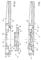
- FIGs. 1A, 1B, 1C, 3 and 4A illustrate apparatus for dry chemical analysis of fluids constructed and operative in accordance with a preferred embodiment of the present invention and comprising a generally elongated shaped filter holder 10 having a base member 12 approximately 5cm long, 2 cm wide and 0.5 cm thick with a top surface 20 and a bottom surface 22.
- One end of the base member 12 has a typically circular depression 14 extending from top surface 20 toward bottom surface 22.
- the diameter of depression 14 is approximately 1.2 cm at the level of top surface of 20.
- At a depth of 0.10 cm depression 14 sharply narrows to a diameter of 0.70 cm forming a ledge 24.
- Ledge 24 separates upper portion 25 of depression 14 from a lower portion 26.
- At the level of ledge 24 depression 14 has a wall in which a notch 40 is formed.
- Lower portion 26 has a base 44 which is approximately 0.20 cm from top surface 20 and 0.1 cm from ledge 24 and from which a bore 46 extends to the bottom surface 22 of base member 12.
- Filter 16 is disposed in the lower portion 26 of depression 14. Filter 16 is typically 0.1 mm - 1.0 mm thick and has approximately the same diameter as the lower portion 26 of depression 14.
- Filter 16 is retained in depression 14 by filter retaining apparatus 18.
- Filter retaining apparatus 18 has a solid portion 34 surrounding an irregular mesh surface portion 32.
- Irregular mesh surface portion 32 has an average mesh opening of approximately 2 - 4 mm.
- Filter retaining apparatus 18 additionally has an upper portion 28 and a lower portion 30.
- the solid portion 34 of filter retaining apparatus 18 has a side surface from which a flange 38 laterally extends.
- the lower portion 30 of filter retaining apparatus 18 includes protuberances 42 depending perpendicularly from the mesh surface portion 32 and from a part of the solid portion 34 of filter retaining apparatus 18.
- Lower portion 30 of filter retaining apparatus 18 is sized to fit tightly into lower portion 26 of depression 14 with the protuberances 42 abutting filter 16.
- Upper portion 28 of filter retaining apparatus 18 is sized to fit tightly into upper portion 25 of depression 14.
- the solid portion 34 of filter retaining apparatus 18 rests on ledge 24 and flange 38 engages notch 40 to mechanically join filter retaining apparatus 18 to base member 12. Filter 16 is thus securely retained in depression 14.
- Filter 16 is typically a multilayer filter in which the top layer is a glass fiber filter and the bottom layer is a reagent impregnated nylon membrane.
- Filter retaining apparatus 18 and base member 12 are typically fabricated from a plastic material which although generally rigid is flexible enough to permit flange 38 to flex during assembly of apparatus 10.
- filter 16 is first placed in depression 14. Retaining apparatus 18 is then inserted in depression 14 and gently pressed toward bottom surface 22 of base member 12. Flange 38 is deformed until solid portion 34 abuts ledge 24 releasing the pressure on flange 38. Flange 38 then returns to its original shape and engages notch 40.
- Filter retaining apparatus 18 and base member 12 are typically fabricated by injection molding from ABS plastic.
- Other plastics, however, such as polystyrene or polypropylene may alternatively be used as well as other fabrication methods such as blow molding.
- filter retaining apparatus 18 and base member 12 are treated to make their surfaces hydrophilic.
- This treatment typically includes first exposing filter retaining apparatus 18 and base member 12 to a corona discharge for approximately 1 - 5 seconds at a distance of 1mm from the electrode.
- the treatment additionally typically includes a brief complete immersion in a surfactant solution such as a 0.01 - 0.5M solution of dioctyl sulfosuccinate sodium salt dissolved in a 4:6 alcohol water mixture.
- filter retaining apparatus 18 and base member 12 may be fabricated from a hydrophilic material.
- a sample liquid typically whole blood
- the blood is generally evenly distributed in the space over the glass fiber filter layer by the mesh surface portion 32 and the protuberances 42.
- the blood is then drawn through the glass fiber filter by gravity and capillary action.
- the glass fiber filter separates the formed portion of the blood, such as erythrocytes, from the liquid portion which is passed on to the reagent impregnated nylon membrane.
- FIG. 2A, 2B, 2C and 5 illustrate an alternative preferred embodiment of the present invention.
- This embodiment of apparatus for dry chemical analysis of fluids differs from the embodiment of Figs 1A, 1B, 1C, 3 and 4A only in that filter retaining apparatus 118 and base member 112 have respective bottom surfaces 119 and top surfaces 113 which are congruent at all points except depression 114.
- Retaining member 118 and base member 112 are joined mechanically in apparatus similar to that illustrated in the embodiment of Figs. 1A, 1B, 1C, 3 and 5.
- Base member 112 has a perimeter surface 121 formed with a notch 142.
- Retaining member 118 has a perimeter surface 123 formed with a flange 138.
- flange 138 engages notch 142 mechanically joining filter retaining apparatus 118 to base member 112.
- Fig. 4B illustrates an alternative embodiment of the invention in which a flange 43 depends perpendicularly from the solid portion of the filter retaining apparatus 18 and is spaced from filter 16.
- Flange 43 which is adjacent to and surrounding the mesh surface portion 32 is spaced from the filter 16 to increase the rate of flow of sample liquid to filter 16 and to reduce seepage of the sample liquid from depression 14 along the interface between base member 12 and the solid portion 34 of filter retaining apparatus 18.
Landscapes
- Health & Medical Sciences (AREA)
- Life Sciences & Earth Sciences (AREA)
- Immunology (AREA)
- Engineering & Computer Science (AREA)
- Hematology (AREA)
- Urology & Nephrology (AREA)
- Molecular Biology (AREA)
- Chemical & Material Sciences (AREA)
- Biomedical Technology (AREA)
- Physics & Mathematics (AREA)
- Biochemistry (AREA)
- Cell Biology (AREA)
- Food Science & Technology (AREA)
- Medicinal Chemistry (AREA)
- Biotechnology (AREA)
- Analytical Chemistry (AREA)
- Microbiology (AREA)
- General Health & Medical Sciences (AREA)
- General Physics & Mathematics (AREA)
- Pathology (AREA)
- Sampling And Sample Adjustment (AREA)
- Investigating Or Analysing Biological Materials (AREA)
- Investigating Or Analyzing Non-Biological Materials By The Use Of Chemical Means (AREA)
Abstract
Claims (20)
- Appareil pour l'analyse chimique sèche de fluides, comprenant :
un filtre ; et
un moyen de support du filtre incluant :
un élément de base définissant un emplacement de support du filtre ; et
un moyen de maintien du filtre incluant un treillis arrangé pour maintenir ledit filtre audit emplacement de support du filtre en relation espacée par rapport audit treillis. - Appareil selon la revendication 1, dans lequel ledit élément de base est rigide.
- Appareil selon la revendication 1, dans lequel ledit emplacement de support du filtre inclut une dépression.
- Appareil selon la revendication 3, dans lequel ledit élément de base est allongé et comprend des première et seconde extrémités, et dans lequel ladite dépression dans ledit élément de base est situé à ladite première extrémité.
- Appareil selon l'une quelconque des revendications précédentes, dans lequel une partie dudit moyen de maintien du filtre bute contre ledit élément de base, et ledit élément de base et ledit moyen de maintien du filtre sont joints mécaniquement.
- Appareil selon l'une quelconque des revendications précédentes, dans lequel ledit moyen de maintien du filtre a une surface latérale extérieure et ledit élément de base a une surface latérale intérieure qui inclut ladite surface latérale dudit moyen de maintien du filtre.
- Appareil selon l'une quelconque des revendications précédentes, dans lequel une partie de ladite surface latérale dudit moyen de maintien du filtre est munie d'un épaulement, et une partie de ladite surface latérale dudit élément de base est munie d'une encoche, et dans lequel ledit épaulement s'engage avec ladite encoche pour joindre mécaniquement ledit moyen de maintien du filtre audit élément de base.
- Appareil selon l'une quelconque des revendications 1 à 6, dans lequel ledit moyen de maintien de filtre inclut en plus une partie extérieure solide entourant ledit treillis.
- Appareil selon l'une quelconque des revendications 3 à 8, dans lequel ledit moyen de maintien du filtre inclut en outre des protubérances dépendant verticalement dudit treillis, et dans lequel lesdites protubérances butent contre ledit filtre pour maintenir ledit filtre dans ladite dépression et pour obtenir une distribution régulière d'un échantillon liquide sur la surface dudit filtre.
- Appareil selon les revendications 8 et 9, dans lequel ledit moyen de maintien du filtre inclut en plus des protubérances dépendant perpendiculairement d'une partie de ladite partie solide de façon adjacente audit treillis, et dans lequel lesdites protubérances butent contre ledit filtre pour maintenir ledit filtre dans ladite dépression.
- Appareil selon les revendications 8 et 9, dans lequel ledit moyen de maintien du filtre inclut en plus un épaulement dépendant perpendiculairement de ladite partie solide de façon adjacente audit treillis, et dans lequel ledit épaulement est espacé dudit filtre pour accroître la vitesse de flux de l'échantillon liquide audit filtre et pour réduire une infiltration de l'échantillon liquide à partir de ladite dépression, le long une interface entre ledit élément de base et ladite partie solide dudit moyen de maintien du filtre.
- Appareil selon l'une quelconque des revendications précédentes, dans lequel ledit moyen de support du filtre est fabriqué à partir d'un matériau hydrophile.
- Appareil selon l'une quelconque des revendications 1 à 7, ou 12, dans lequel au moins une surface dudit élément de base est traitée pour conférer une hydrophilie.
- Appareil selon l'une quelconque des revendications 1, ou 4 à 12, dans lequel au moins une surface dudit moyen de maintien du filtre est traité pour conférer une hydrophilie.
- Appareil selon l'une quelconque des revendications 1, 4 à 12, ou 14, dans lequel ledit moyen de maintien du filtre est formé à partir d'une matière plastique moulable par injection.
- Appareil selon l'une quelconque des revendications 1 à 7, 12 ou 13, dans lequel ledit élément de base est formé à partir d'une matière plastique moulable par injection.
- Appareil selon la revendication 1, dans lequel ledit moyen de support du filtre ne dépasse pas 5 cm de longueur, 2 cm de largeur et 0,5 cm de profondeur.
- Appareil selon l'une quelconque des revendications 3 à 7, ou 12 et 13, dans lequel ledit élément de base inclut une ouverture disposée entre ladite dépression et la surface inférieure dudit élément de base pour permettre une communication fluide entre ladite dépression et la surface inférieure dudit élément de base.
- Appareil selon la revendication 1, dans lequel ledit filtre est un filtre à couches multiples.
- Appareil selon la revendication 19, dans lequel une couche dudit filtre à couches multiples inclut un matériau imprégné de réactif.
Applications Claiming Priority (3)
| Application Number | Priority Date | Filing Date | Title |
|---|---|---|---|
| IL9688791A IL96887A (en) | 1991-01-06 | 1991-01-06 | Apparatus for dry chemical analysis of fluids |
| IL96887 | 1991-01-06 | ||
| PCT/NL1992/000002 WO1992012425A1 (fr) | 1991-01-06 | 1992-01-06 | Appareil servant a effectuer une analyse chimique seche de fluides |
Publications (2)
| Publication Number | Publication Date |
|---|---|
| EP0565594A1 EP0565594A1 (fr) | 1993-10-20 |
| EP0565594B1 true EP0565594B1 (fr) | 1995-06-07 |
Family
ID=11061943
Family Applications (1)
| Application Number | Title | Priority Date | Filing Date |
|---|---|---|---|
| EP92902939A Expired - Lifetime EP0565594B1 (fr) | 1991-01-06 | 1992-01-06 | Appareil servant a effectuer une analyse chimique seche de fluides |
Country Status (6)
| Country | Link |
|---|---|
| EP (1) | EP0565594B1 (fr) |
| JP (1) | JP2958115B2 (fr) |
| DE (1) | DE69202855T2 (fr) |
| ES (1) | ES2073285T3 (fr) |
| IL (1) | IL96887A (fr) |
| WO (1) | WO1992012425A1 (fr) |
Families Citing this family (6)
| Publication number | Priority date | Publication date | Assignee | Title |
|---|---|---|---|---|
| US5104619A (en) * | 1990-01-24 | 1992-04-14 | Gds Technology, Inc. | Disposable diagnostic system |
| US5658801A (en) * | 1994-05-03 | 1997-08-19 | Spectral Diagnostics Inc. | Medical test kit |
| EP1043588A4 (fr) * | 1997-12-25 | 2001-08-22 | Mochida Pharm Co Ltd | Analyseur pour echantillons liquides |
| WO2001071341A1 (fr) * | 2000-03-24 | 2001-09-27 | Arkray, Inc. | Dispositif auxiliaire d'introduction d'echantillons |
| JP4656992B2 (ja) * | 2005-04-14 | 2011-03-23 | 積水化学工業株式会社 | マイクロフィルターユニット |
| JP5586842B2 (ja) * | 2006-10-19 | 2014-09-10 | デンカ生研株式会社 | 試料ろ過フィルターを用いる簡易メンブレンアッセイ方法及びキット |
Family Cites Families (3)
| Publication number | Priority date | Publication date | Assignee | Title |
|---|---|---|---|---|
| EP0269876B1 (fr) * | 1986-11-24 | 1993-08-18 | Abbott Laboratories | Dispositif de concentration d'échantillon pour un appareil analytique de phase solide |
| US4912034A (en) * | 1987-09-21 | 1990-03-27 | Biogenex Laboratories | Immunoassay test device and method |
| NL8800796A (nl) * | 1988-03-29 | 1989-10-16 | X Flow Bv | Werkwijze voor de chemische analyse van bestanddelen van een lichaamsvloeistof, alsmede een testinrichting en testpakket voor een dergelijke analyse. |
-
1991
- 1991-01-06 IL IL9688791A patent/IL96887A/en not_active IP Right Cessation
-
1992
- 1992-01-06 DE DE69202855T patent/DE69202855T2/de not_active Expired - Lifetime
- 1992-01-06 JP JP4503110A patent/JP2958115B2/ja not_active Expired - Lifetime
- 1992-01-06 WO PCT/NL1992/000002 patent/WO1992012425A1/fr not_active Ceased
- 1992-01-06 ES ES92902939T patent/ES2073285T3/es not_active Expired - Lifetime
- 1992-01-06 EP EP92902939A patent/EP0565594B1/fr not_active Expired - Lifetime
Also Published As
| Publication number | Publication date |
|---|---|
| DE69202855D1 (de) | 1995-07-13 |
| DE69202855T2 (de) | 1995-10-26 |
| JP2958115B2 (ja) | 1999-10-06 |
| IL96887A0 (en) | 1992-03-29 |
| IL96887A (en) | 1996-08-04 |
| ES2073285T3 (es) | 1995-08-01 |
| EP0565594A1 (fr) | 1993-10-20 |
| JPH06504621A (ja) | 1994-05-26 |
| WO1992012425A1 (fr) | 1992-07-23 |
Similar Documents
| Publication | Publication Date | Title |
|---|---|---|
| CA2263976C (fr) | Dispositif a filtres integres destine au filtrage d'echantillons fluides | |
| JP3387649B2 (ja) | 点着チップ | |
| EP0478459B1 (fr) | Aiguille de prélèvement de sang | |
| US6045757A (en) | Membrane filter pipette tip | |
| US5800785A (en) | Testing device for liquid and liquid suspended samples | |
| JP2937568B2 (ja) | 自己計測式流体分析器具 | |
| US4088448A (en) | Apparatus for sampling, mixing the sample with a reagent and making particularly optical analyses | |
| US8431092B2 (en) | Biochip holder and method of collecting fluid | |
| JPS61144571A (ja) | 液体標本の細胞状成分と非細胞状成分の自動分離装置 | |
| KR840006852A (ko) | 단일체의 시약 분배기 | |
| US5204063A (en) | Eluent release system and automated assay device | |
| JP2005177749A (ja) | サンプルを処理するためのマイクロタイタ・プレート、システム及び方法 | |
| US5409832A (en) | Membrane holder for use in an assay device | |
| JP2001525553A (ja) | 支持体と被覆に挟まれた中間層を備える毛管活性試験要素 | |
| JPH0664062B2 (ja) | ウエル型診断用プレート装置 | |
| KR970058731A (ko) | 혈액 여과 장치 | |
| EP0565594B1 (fr) | Appareil servant a effectuer une analyse chimique seche de fluides | |
| US5389338A (en) | Apparatus for dry chemical analysis of fluids | |
| CN107036848B (zh) | 一种样本收集及检测的装置 | |
| KR100244016B1 (ko) | 액체표본 수집장치 | |
| EP0321145A3 (fr) | Dispositif immunodiagnostique | |
| CN114859068A (zh) | 试剂盒及poct血细胞分析仪 | |
| JPH04228062A (ja) | 接種器及び組立体 | |
| CN112218580B (zh) | 生物流体微量样品管理装置 | |
| JP3833830B2 (ja) | 血液成分分離器 |
Legal Events
| Date | Code | Title | Description |
|---|---|---|---|
| PUAI | Public reference made under article 153(3) epc to a published international application that has entered the european phase |
Free format text: ORIGINAL CODE: 0009012 |
|
| 17P | Request for examination filed |
Effective date: 19930617 |
|
| AK | Designated contracting states |
Kind code of ref document: A1 Designated state(s): CH DE ES FR LI NL |
|
| 17Q | First examination report despatched |
Effective date: 19940114 |
|
| RAP1 | Party data changed (applicant data changed or rights of an application transferred) |
Owner name: ORGENICS LTD. |
|
| GRAA | (expected) grant |
Free format text: ORIGINAL CODE: 0009210 |
|
| AK | Designated contracting states |
Kind code of ref document: B1 Designated state(s): CH DE ES FR LI NL |
|
| REF | Corresponds to: |
Ref document number: 69202855 Country of ref document: DE Date of ref document: 19950713 |
|
| REG | Reference to a national code |
Ref country code: ES Ref legal event code: FG2A Ref document number: 2073285 Country of ref document: ES Kind code of ref document: T3 |
|
| ET | Fr: translation filed | ||
| PLBE | No opposition filed within time limit |
Free format text: ORIGINAL CODE: 0009261 |
|
| STAA | Information on the status of an ep patent application or granted ep patent |
Free format text: STATUS: NO OPPOSITION FILED WITHIN TIME LIMIT |
|
| 26N | No opposition filed | ||
| PGFP | Annual fee paid to national office [announced via postgrant information from national office to epo] |
Ref country code: NL Payment date: 20030131 Year of fee payment: 12 |
|
| PG25 | Lapsed in a contracting state [announced via postgrant information from national office to epo] |
Ref country code: NL Free format text: LAPSE BECAUSE OF NON-PAYMENT OF DUE FEES Effective date: 20040801 |
|
| NLV4 | Nl: lapsed or anulled due to non-payment of the annual fee |
Effective date: 20040801 |
|
| PGFP | Annual fee paid to national office [announced via postgrant information from national office to epo] |
Ref country code: CH Payment date: 20110112 Year of fee payment: 20 Ref country code: DE Payment date: 20101230 Year of fee payment: 20 Ref country code: FR Payment date: 20110128 Year of fee payment: 20 |
|
| PGFP | Annual fee paid to national office [announced via postgrant information from national office to epo] |
Ref country code: ES Payment date: 20110216 Year of fee payment: 20 |
|
| REG | Reference to a national code |
Ref country code: DE Ref legal event code: R071 Ref document number: 69202855 Country of ref document: DE |
|
| REG | Reference to a national code |
Ref country code: DE Ref legal event code: R071 Ref document number: 69202855 Country of ref document: DE |
|
| REG | Reference to a national code |
Ref country code: CH Ref legal event code: PL |
|
| REG | Reference to a national code |
Ref country code: ES Ref legal event code: FD2A Effective date: 20120411 |
|
| PG25 | Lapsed in a contracting state [announced via postgrant information from national office to epo] |
Ref country code: ES Free format text: LAPSE BECAUSE OF EXPIRATION OF PROTECTION Effective date: 20120107 Ref country code: DE Free format text: LAPSE BECAUSE OF EXPIRATION OF PROTECTION Effective date: 20120107 |