EP0565921A2 - Installation de traitement et de manutention d'eau pluviale pour l'utilisation comme eau industrielle ou de traitement en vue d'infiltration ou d'introduction dans un évacuateur - Google Patents
Installation de traitement et de manutention d'eau pluviale pour l'utilisation comme eau industrielle ou de traitement en vue d'infiltration ou d'introduction dans un évacuateur Download PDFInfo
- Publication number
- EP0565921A2 EP0565921A2 EP93104881A EP93104881A EP0565921A2 EP 0565921 A2 EP0565921 A2 EP 0565921A2 EP 93104881 A EP93104881 A EP 93104881A EP 93104881 A EP93104881 A EP 93104881A EP 0565921 A2 EP0565921 A2 EP 0565921A2
- Authority
- EP
- European Patent Office
- Prior art keywords
- filter
- water
- plant according
- rainwater
- overflow
- Prior art date
- Legal status (The legal status is an assumption and is not a legal conclusion. Google has not performed a legal analysis and makes no representation as to the accuracy of the status listed.)
- Withdrawn
Links
Images


Classifications
-
- E—FIXED CONSTRUCTIONS
- E03—WATER SUPPLY; SEWERAGE
- E03F—SEWERS; CESSPOOLS
- E03F5/00—Sewerage structures
- E03F5/10—Collecting-tanks; Equalising-tanks for regulating the run-off; Laying-up basins
- E03F5/105—Accessories, e.g. flow regulators or cleaning devices
-
- C—CHEMISTRY; METALLURGY
- C02—TREATMENT OF WATER, WASTE WATER, SEWAGE, OR SLUDGE
- C02F—TREATMENT OF WATER, WASTE WATER, SEWAGE, OR SLUDGE
- C02F1/00—Treatment of water, waste water, or sewage
- C02F1/001—Processes for the treatment of water whereby the filtration technique is of importance
- C02F1/004—Processes for the treatment of water whereby the filtration technique is of importance using large scale industrial sized filters
-
- E—FIXED CONSTRUCTIONS
- E03—WATER SUPPLY; SEWERAGE
- E03B—INSTALLATIONS OR METHODS FOR OBTAINING, COLLECTING, OR DISTRIBUTING WATER
- E03B11/00—Arrangements or adaptations of tanks for water supply
-
- E—FIXED CONSTRUCTIONS
- E03—WATER SUPPLY; SEWERAGE
- E03B—INSTALLATIONS OR METHODS FOR OBTAINING, COLLECTING, OR DISTRIBUTING WATER
- E03B3/00—Methods or installations for obtaining or collecting drinking water or tap water
- E03B3/02—Methods or installations for obtaining or collecting drinking water or tap water from rain-water
- E03B3/03—Special vessels for collecting or storing rain-water for use in the household, e.g. water-butts
-
- E—FIXED CONSTRUCTIONS
- E03—WATER SUPPLY; SEWERAGE
- E03F—SEWERS; CESSPOOLS
- E03F5/00—Sewerage structures
- E03F5/14—Devices for separating liquid or solid substances from sewage, e.g. sand or sludge traps, rakes or grates
-
- C—CHEMISTRY; METALLURGY
- C02—TREATMENT OF WATER, WASTE WATER, SEWAGE, OR SLUDGE
- C02F—TREATMENT OF WATER, WASTE WATER, SEWAGE, OR SLUDGE
- C02F1/00—Treatment of water, waste water, or sewage
- C02F1/28—Treatment of water, waste water, or sewage by sorption
- C02F1/281—Treatment of water, waste water, or sewage by sorption using inorganic sorbents
-
- C—CHEMISTRY; METALLURGY
- C02—TREATMENT OF WATER, WASTE WATER, SEWAGE, OR SLUDGE
- C02F—TREATMENT OF WATER, WASTE WATER, SEWAGE, OR SLUDGE
- C02F1/00—Treatment of water, waste water, or sewage
- C02F1/28—Treatment of water, waste water, or sewage by sorption
- C02F1/283—Treatment of water, waste water, or sewage by sorption using coal, charred products, or inorganic mixtures containing them
-
- C—CHEMISTRY; METALLURGY
- C02—TREATMENT OF WATER, WASTE WATER, SEWAGE, OR SLUDGE
- C02F—TREATMENT OF WATER, WASTE WATER, SEWAGE, OR SLUDGE
- C02F1/00—Treatment of water, waste water, or sewage
- C02F1/30—Treatment of water, waste water, or sewage by irradiation
- C02F1/32—Treatment of water, waste water, or sewage by irradiation with ultraviolet light
-
- C—CHEMISTRY; METALLURGY
- C02—TREATMENT OF WATER, WASTE WATER, SEWAGE, OR SLUDGE
- C02F—TREATMENT OF WATER, WASTE WATER, SEWAGE, OR SLUDGE
- C02F1/00—Treatment of water, waste water, or sewage
- C02F1/72—Treatment of water, waste water, or sewage by oxidation
- C02F1/78—Treatment of water, waste water, or sewage by oxidation with ozone
-
- C—CHEMISTRY; METALLURGY
- C02—TREATMENT OF WATER, WASTE WATER, SEWAGE, OR SLUDGE
- C02F—TREATMENT OF WATER, WASTE WATER, SEWAGE, OR SLUDGE
- C02F2103/00—Nature of the water, waste water, sewage or sludge to be treated
- C02F2103/001—Runoff or storm water
-
- C—CHEMISTRY; METALLURGY
- C02—TREATMENT OF WATER, WASTE WATER, SEWAGE, OR SLUDGE
- C02F—TREATMENT OF WATER, WASTE WATER, SEWAGE, OR SLUDGE
- C02F2201/00—Apparatus for treatment of water, waste water or sewage
- C02F2201/002—Construction details of the apparatus
- C02F2201/003—Coaxial constructions, e.g. a cartridge located coaxially within another
-
- Y—GENERAL TAGGING OF NEW TECHNOLOGICAL DEVELOPMENTS; GENERAL TAGGING OF CROSS-SECTIONAL TECHNOLOGIES SPANNING OVER SEVERAL SECTIONS OF THE IPC; TECHNICAL SUBJECTS COVERED BY FORMER USPC CROSS-REFERENCE ART COLLECTIONS [XRACs] AND DIGESTS
- Y02—TECHNOLOGIES OR APPLICATIONS FOR MITIGATION OR ADAPTATION AGAINST CLIMATE CHANGE
- Y02A—TECHNOLOGIES FOR ADAPTATION TO CLIMATE CHANGE
- Y02A20/00—Water conservation; Efficient water supply; Efficient water use
- Y02A20/108—Rainwater harvesting
-
- Y—GENERAL TAGGING OF NEW TECHNOLOGICAL DEVELOPMENTS; GENERAL TAGGING OF CROSS-SECTIONAL TECHNOLOGIES SPANNING OVER SEVERAL SECTIONS OF THE IPC; TECHNICAL SUBJECTS COVERED BY FORMER USPC CROSS-REFERENCE ART COLLECTIONS [XRACs] AND DIGESTS
- Y02—TECHNOLOGIES OR APPLICATIONS FOR MITIGATION OR ADAPTATION AGAINST CLIMATE CHANGE
- Y02W—CLIMATE CHANGE MITIGATION TECHNOLOGIES RELATED TO WASTEWATER TREATMENT OR WASTE MANAGEMENT
- Y02W10/00—Technologies for wastewater treatment
- Y02W10/30—Wastewater or sewage treatment systems using renewable energies
- Y02W10/37—Wastewater or sewage treatment systems using renewable energies using solar energy
Definitions
- the invention relates to a system for the preparation, storage and demand of rainwater paved areas such as roofs, streets and courtyards for use as process water in households, commerce, industry and public buildings or for the purpose of seepage or discharge into a receiving water.
- the system mainly consists of a filter system with a sediment separator, a storage tank with devices for flow control and sedimentation and a control unit.
- Other components of the system are facilities for level control, pumping the process water, arrangements for protection against backflow from the sewage system, facilities for the disinfection and biological fixation of pollutants, facilities for the biological degradation of organic substances, arrangements for the implementation of pipes, lines and cables through storage tanks - and building walls, arrangements for securing the buoyancy of the storage tank, facilities for infiltration of the overflow water.
- Concrete or plastic containers are used for water storage / 2/3/12/14/16 /, which are housed in the ground or in basements.
- drinking water flows into the storage tank via / a / 2/4 / via a float-controlled valve in the storage tank.
- the water is usually sucked out of the storage tank through a so-called foot valve by a pump and passed on to the consumers / 5/9/16 /.
- filters, accumulators, pumps and controls are partly combined to form an assembly unit / 1 0/16 /.
- the arrangement / 9 / in which the pump and filter are arranged above the reservoir is known as a compact design for systems with underground storage.
- a pressure is required which is given by the height of the water column above the filter.
- the filter In order to achieve a high level in the storage tank, the filter should be mounted as high as possible. This requirement conflicts with the requirement for frost-proof laying of the rain lines and the frost-proof installation of the filter. Safe operation is not guaranteed in the event of frost and condensation caused by sunlight.
- the storage tank and, if applicable, the filter are installed in the basement, the fill levels are above the frost-free area in the ground in normal buildings. This means that it is not possible to lay the rain supply lines in the ground outside the building.
- the known storage tanks for underground installation have no protection against buoyancy in groundwater or backwater.
- the known systems have no protection against backflow from the sewer network into the overflow of the systems.
- the effective filter area of these filters is determined by the horizontal cross section of the filter chamber. This results in relatively small effective filter areas in relation to the area used and the size of the filter chamber / 2/3/5/12/14 /.
- the pressure head of the water column above the filter is available to overcome the filter resistance because the filter flows through from top to bottom. As a result, there are only small usable overflow levels. With arrangement / 14 / only coarse substances are retained, the filter basket has more the function of a rake.
- the known filters with filter bed / 2/3/5 / can only be cleaned with great difficulty because there are no precautions for rational removal of the bed. Inserts made of mineral fibers, plastic fleece or similar cannot be regenerated and must be replaced after contamination.
- the small layer thickness and the small cross-section of the filter bed in relation to the size of the filter ensures only limited cleaning; Removable, coarser substances such as moss, leaves and bird droppings are entered into the filter / 2/3/5/9/10/12 / and clog the filter prematurely.
- the rainwater in the known filters must be supplied from above; Because of the necessary slope of the rain pipes in the ground, this means that often only the water from one downpipe per filter can be used; For this reason, the filter must be installed near the downpipe.
- the well-known rain collectors / 11/13/15 / for mounting in the downpipe allow rainwater to be drawn from several downpipes and to be discharged into a single filter shaft or directly into a building on a corresponding slope without the risk of freezing.
- further pipes are required to drain the usable rainwater.
- the filter acts as a surface filter and is therefore quickly clogged by contaminants.
- the filter cannot be regenerated or backwashed.
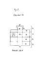
- the rainwater flows from the drainage pipes (ENT) laid in accordance with the standards in a frost-proof depth in the lower area through several inlet connections (e.g. KG push-in sockets) into the filter system (S) according to FIG. 2, the flow speed is reduced in a sedimentation zone (SZ ), coarse dirt particles sediment in an inserted, removable bottom cup (TS) which stands out of the bottom (B) of the filter housing (FIG), the water then flows between the housing walls (FIG) and the coaxial, cylindrical perforated walls of the filter basket (FK ) high, through the perforation of the filter basket FK perpendicular to the filter basket through a filter mass (FS), then over the inner perforated tube (FR) to the outlet (AG).
- SZ sedimentation zone
- TS coarse dirt particles sediment in an inserted, removable bottom cup
- FK coaxial, cylindrical perforated walls of the filter basket
- FK filter mass
- This bypass takes into account the fact that, with economically reasonable dimensions of the filter, it is not possible to conduct heavy rain drains completely through a filter. Experiments have shown that it is also not necessary to filter these heavy rain drains, since they do not carry any relevant dirt, because the atmospheric dry deposition on the roof surfaces has already been rinsed off before the peak drain is reached. Depending on the river, the raw water can reach the storage tank (VB) without losses in the event of extremely heavy rain events.
- the filter basket (FK) can also be designed with a polygonal cross-section, e.g. B. in the form of a pleated filter to enlarge the surface. Parallel filter walls are also possible.
- the pipe (FR) is then replaced by a second filter wall parallel to the filter wall (FK).
- the filter basket can be plugged into a conical or cylindrical sleeve (MF), whereby the known seals of commercially available sewer pipes can be used.
- MF conical or cylindrical sleeve
- a flat-sealing version is also possible, in which the basket comes to rest on the base (BF), if necessary with an interposed elastic seal.
- the design of the filter system results from the fact that outflows with irregular distribution and outflow peaks have to be cleaned simultaneously by thunderstorm rain. This can only be achieved with a depth filter, which can absorb a high dirt load with a low filter resistance without clogging. Surface filters such as fine sieves are ruled out because they can be blocked by a single rain event.
- the connection of a sedimentation zone (SZ) before the actual filter stops quickly sedimentable substances, which make up a major part of the total dirt load, away from the filter, so that long cleaning intervals and service life of the filter result.
- SZ sedimentation zone
- the coaxial-cylindrical design of the filter unit results in favorable relationships between filter performance and size.
- the filter bed (FS) consists of granular, rounded or sharply broken material. Clay granulate, expanded stone chippings, broken bricks, volcanic or industrial slag, pumice or tufa, natural stone chippings or gravel, plastic granules, activated or charcoal, wood or bark are used. The release of biocidal substances from bark or wood, for example, can limit the growth of microorganisms.
- the water is cleaned as it passes through the cleaning shaft in the order of sedimentation in the zone (SZ), sieving through the filter basket (FK) and deep filtration in the bed (FS); Particles and suspended matter are adsorbed on the filter grain of the filter mass (FS); As a result, fine substances that are smaller than the pore size of the filter can be retained without increasing the filter resistance by clogging the pores.
- SZ sedimentation in the zone
- FK filter basket
- FS deep filtration in the bed
- FS filter grain of the filter mass
- fine substances that are smaller than the pore size of the filter can be retained without increasing the filter resistance by clogging the pores.
- the filter bed can be regenerated quickly and inexpensively by backwashing or removing and spraying the filter bed with water. That e.g. Depending on the intensity of the discharge, drain water coming from the downpipes accumulates in the supply lines up to the bypass height (BY). This hydrostatic pressure level is used to overcome the filter resistance.
- the effective filter cross-section therefore adapts to the volume flow of the incoming water: With increasing flow and increasing filter resistance, the water level (WS) in the inlet area (EB) rises, and with it the flow through the filter cross-section. Due to the variable overflow in the supply lines, sufficient pressure is available for filtration, with frost-proof, standard-compliant routing of the supply lines and a still water level below frost depth, without the fill level in the storage tank (VB) being lost. If the filter basket (FK) is flooded during a rain event, the water level in the supply lines will exceed the frost-free depth; However, only heavy rain events, which experience has shown that cannot occur in ground frost, lead to flooding; Frost protection is guaranteed in every season.
- the filter basket (FK) can be plugged in or fastened in a sleeve (MF) with a thread or with a bayonet lock so that the entire filter basket can be removed and emptied for cleaning the filter bed (FS).
- the pipe connections of the filter housing are designed as push-in sockets or pipe nipple plug ends, so that conventional drainage pipes of standardized nominal widths can be connected immediately by plugging them in.
- the grain size distribution of the filter bed can vary with the height in order to achieve a uniform filter speed
- a pipe (RSL) for backwashing the filter bed can be arranged in the floor area below the filter bed;
- the inlet of this backwash line (RSL) can be led upwards into the area (BY) and provided with a screw flange or can be plugged into the base (BF).
- BY area
- BF base
- ABS shut-off grille
- the height of the overflow (UE) is above the backflow level of the sewage system and determines the maximum level that occurs in the system in the frost-free period.
- the filter basket (FK) either sits on a base (BF) with an integrated drain line or sits on feet (not shown) on the shaft floor (B), or forms a structural unit with the floor cup (TS), or lies on laterally protruding (not shown) projections of the filter housing.
- the filter tube FR can be slotted or provided with holes (eg plastic well tube) or consist of a wire mesh;
- a flushing line (BSL) with nozzles for whirling up the sediment can be provided in the bottom area.
- This floor flushing line (BSL) can be combined with the backflushing line (RSL).
- the floor flushing device is used particularly when no removable floor cup is provided, or when several filter baskets (FK) are mounted in parallel in a common filter housing.
- the majority of the substances deposited in the filter are retained in the first centimeters of the filter bed near the outer surface (outer surface of the filter basket FK);
- the service life of the filter depends on the half predominantly from the size of the lateral surface from the filter basket FK.
- the filter resistance can be checked to control the backwashing or display of the cleaning interval by measuring the overflow height (WS) in the inlet area (EB) using mechanical, electrical or electronic devices. Instead of measuring the overflow, the overflow events can also be counted and used to control an automatic backwash. Inexpensive conventional level switches, such as those used in washing machines and dishwashers, can be used for pneumatic / electrical level control.
- the filter basket (FK) and the filter tube (FR) can e.g. are produced inexpensively from well pipes or perforated stainless steel sheets (for the manufacture of washing machine drums), or from the jacket part of washing machine drums.
- the same manufacturing facilities can be used for the production of the filter basket as for the production of washing machine drums:
- For the self-builders and craftsmen the use of 2 or 3 used, used washing machine drums from front loaders, which are placed on top of each other and with each other by riveting, soldering or welding.
- Different filter sizes can be put together inexpensively in series production by combining the standardized and interlocking components (TO), (TK) and (TU) according to FIG. 3.
- the filter housing can be manufactured inexpensively from concrete or plastic;
- the pipe entry sleeves are either cast in during the manufacture of the finished parts, or the corresponding openings are provided and the sleeves are installed later on the construction site.
- the filter system can in particular be manufactured as a unit ready for connection with all connections and pipes.
- the filter system (S) and storage tank (VB) can also form a structural unit that only needs to be lowered into the construction pit on the construction site.
- the filter performance can be adapted to the requirements.
- the hydraulic conditions are preserved; In filter design, only the number of filter baskets increases linearly with the area of the drained area. As a result, the manufacturing costs for the filter basket are reduced by producing large quantities of the same type and size.
- the sealing device (VSE) is injected and rinsing water is injected via the line (RSL) or (BSL).
- This closure device is used to close the supply line to the cistern, while cleaning the filter system (S) by backwashing, or to keep rain contaminated with pollutants out of the storage tank.
- the sealing element In the open state, the sealing element is guided out of the flow through the pipe cross section according to FIG. 5 or 6; This results in a low pressure loss in the closure device.
- the closure device can be manufactured inexpensively by using a commercially available branch piece for drainage pipes (KG or HT pipes); Only the sealing seat (DS) is pressed, glued or welded into the branch piece.
- the seal can be designed as a flat seal as in FIG. 5 or as a conical seal as shown in FIG. 6.
- the control rod (ST1) is guided upwards through a commercially available drainage pipe and ends in the head piece (HT socket plug), which is also made from commercially available molded parts.
- the control rod (ST) is held by a commercially available PG cable strain relief installed in the head piece (HT socket plug).
- the frictional resistance of the control rod can be regulated by the pressure of the cable gland.
- the closure unit can be manufactured as a structural unit with the filter system (S).
- the water level can be kept close to the top of the terrain in the reservoir (VB) during the frost-free period thanks to the locking device.
- the outlet (UE) in the filter housing (FIG) then acts as an overflow.
- SWU opening
- the construction is similar to that of a locking device (VSE); The device is installed in the ground and can be operated from above with the control rod (ST2);
- This device prevents backflow from the sewer network into the store, since in the closed state the possible backflow height is limited by the installation height of the outlet (UE) in the filter housing (FIG).
- UE outlet
- FOG filter housing
- backwater-forming rain events only occur in the frost-free period, so that the facility (SWU) is closed when there is a backlog.
- the device is either operated manually or third-party controlled, for example, by an expansion element.
- block B can be integrated in the manufacture of the container. Feedthroughs within block B that are not required can be closed with a blank plate. Different wall thicknesses (t) can be bridged by placing extension pieces (SR) on the block (B).
- SR extension pieces
- Telecommunication, electrical, gas, oil, water and district heating lines can be laid through a single wall duct.
- the filtered water runs through a pipe bend (RB) into the inlet chamber (BEH1), which is open at the top.
- BEH1 pipe bend
- BOH1 pipe bend
- the incoming water flows upwards out of the chamber (BEH1) and is stratified by the warmer temperature in the top of the reservoir, or at fill levels below the height of the chamber (BEH1), the incoming water flows delayed through the holes (BOH1) and with less kinetic energy into the reservoir.
- the dimensioning of the diameter of the bores (BOH1) leads to an overflow and a calming of the newly flowing water in the inlet chamber (BEH1). In the soil area of (BEH1), sediments can sediment.
- the water enters the sampling chamber (BEH2), which is closed at the top, and through the suction pipe (ASZ) or a submersible pump (not shown) mounted in the sampling chamber into the sampling line (SL).
- the selected flow routing ensures stable stratification in the storage tank and prevents mixing.
- the chamber BEH2
- high-quality water free of suspended matter is achieved in all operating situations (even during rainy events), which eliminates the need for subsequent fine filtration.
- the openings (BOH2) are designed according to FIG. 1 so that they form a barrier against floating substances, falling from the inside to the outside.
- the removal chamber (BEH2 there is an electric floatation device (SC) or another level measuring device, the switching status of which is recorded by the central control (ZS).
- the chambers (BEH1) and (BEH2) can, for example, be manufactured inexpensively from commercially available concrete sewer pipes that are vertical (BEH2) is closed by a lid. Instead of the adjusted concrete pipes, the chambers (BEH) can also be replaced by interior walls of the storage container, which are designed accordingly.
- An ultraviolet light source can be provided in the removal chamber to reduce the growth of microorganisms This light source is controlled according to consumption by the central control (ZS).
- the storage container can be made inexpensively of concrete or plastic and form a structural unit with the chambers (BEH) and the filter system (S).
- All lines from or into the storage tank can be routed through a single opening with the wall duct described under point 4.
- the inlet pipe designed to replenish drinking water flows into the inlet pipe (EL) to prevent the sediment being stirred up.
- the storage tank is provided with an overflow line (ÜLF) of small diameter, which is available via a commercially available, low-cost backflow valve for Drinking water and, if necessary, is connected to the interior of the storage tank via a manual or remote thermally operated valve (ASV).
- the valve (ASV) is activated automatically via a remote temperature sensor or manually, depending on ground frost.
- the remote sensor of the thermostatic valve is attached to the outside of the storage tank or the filter system (S). If the ground freezes, the valve opens and the water level in the system is lowered.
- the installation height of the opening (RDE) at the pipe end determines the lower maximum level. This is chosen so that it is at least at the same level or below the freezing depth.
- the rope is led upwards out of the storage container and the weight pulls the pipe end (RDE) down when the rope slackens.
- the pipe section between the pipe end (RDE) and backflow preventer is then expediently designed as a flexible hose.
- the buoyancy protection (AUF) according to FIGS. 1 and 4 consists of a pipe section with connecting pieces for commercially available drainage pipes and a commercially available non-return valve. If the water level outside the storage tank exceeds the specified height, water can flow into the storage tank to compensate the buoyancy when the storage tank is empty and prevent the storage tank from floating.
- the buoyancy protection can also be integrated in the bottom of the storage container, the drainage tube being able to be replaced by a sieve plate which prevents sand, gravel or earth from penetrating into the arrangement.
- the critical height is then determined via the height of a pipe which is led upwards from the backflow preventer in the storage container. This form of buoyancy protection represents an inexpensive protection without having to weigh down the storage container.
- HM soil or clay
- the level in the chamber (BEH2) is recorded by a central control and the feed pump is switched off when the water level falls below a specified minimum.
- the water level in the free area (FA) of the storage tank is checked via a float switch or another device for level measurement, and the drinking water run-on is then controlled via a solenoid valve.
- the pumped operating water quantity is estimated by measuring the pump running time and then the UV lamp in the extraction chamber (BEH2) and the automatic backwashing of the filter system (S) are controlled.
- the water pressure on the pressure side of the pump is controlled by an electro-pneumatic switch by controlling the pump.
- the filter housing can be extended downwards in order to accommodate excess water and, if necessary, drainage water.
- the filter housing with the walls (WB) and the bottom (BB) serves in this case to achieve an enlarged contact area with the gravel fill surrounding the filter housing and the storage container, in order to ensure problem-free seepage in the case of a conductive substrate.
- the filter system can be used as a separate unit for cleaning rain runoff from sealed surfaces, which can then be cleaned and fed to the infiltration or a receiving water.
- a mounting unit that is fully assembled on a frame or a plate and consists of a control system with cabling, shut-off valves, screw connections, pipes, membrane pressure vessels, membrane pressure switches, solenoid valve for drinking water after-running, free drinking water inlet in the make-up line, water meter for rain and drinking water consumption and, if applicable, a feed pump for Installation in buildings enables quick installation on the construction site.
- the peak runoff value of a building with a rainwater harvesting system as described here is considerably lower than with conventional drainage. Canal cross-sections, rainwater retention or treatment basins can thereby be reduced. If the excess water seeps away or is fed into a surface water, the sewer network can be manufactured considerably more cost-effectively.
- Wastewater treatment plants are usually designed for twice the dry weather runoff. Even low rain intensities lead to this value being exceeded.
- the wastewater load, which exceeds twice the dry weather runoff, is channeled past the wastewater treatment plant into the receiving water. This overflow discharge represents an important water polluter. Keeping surface runoff of sealed surfaces from the sewer network is the only way to prevent this contamination of the receiving water.
- the water quality enables the use of detergent formulations without ingredients for water softening.
- the problematic compounds phosphate and NTA no longer get into the wastewater by washing clothes. This relieves wastewater treatment plants and receiving water. In addition to saving drinking water, the consistent use and infiltration of rainwater also has beneficial effects on wastewater disposal.
Landscapes
- Engineering & Computer Science (AREA)
- Life Sciences & Earth Sciences (AREA)
- Hydrology & Water Resources (AREA)
- Water Supply & Treatment (AREA)
- Health & Medical Sciences (AREA)
- Public Health (AREA)
- Environmental & Geological Engineering (AREA)
- Structural Engineering (AREA)
- Chemical & Material Sciences (AREA)
- Organic Chemistry (AREA)
- Sewage (AREA)
- Filtration Of Liquid (AREA)
Applications Claiming Priority (2)
| Application Number | Priority Date | Filing Date | Title |
|---|---|---|---|
| DE4209429 | 1992-03-24 | ||
| DE19924209429 DE4209429A1 (de) | 1992-03-24 | 1992-03-24 | Anlage zur Aufbereitung, Speicherung und Förderung von Regenwasser zur Nutzung als Brauchwasser in Haushalt, Gewerbe, und öffentlichen Gebäuden und zur Regenwasserbehandlung zum Zwecke der Versickerung oder der Einleitung in einen Vorfluter |
Publications (2)
| Publication Number | Publication Date |
|---|---|
| EP0565921A2 true EP0565921A2 (fr) | 1993-10-20 |
| EP0565921A3 EP0565921A3 (en) | 1993-12-29 |
Family
ID=6454815
Family Applications (1)
| Application Number | Title | Priority Date | Filing Date |
|---|---|---|---|
| EP19930104881 Withdrawn EP0565921A3 (en) | 1992-03-24 | 1993-03-24 | Rain water treating and conveying installation for use as industrial water or for treatment for the purpose of infiltration or inflow in receiving water |
Country Status (2)
| Country | Link |
|---|---|
| EP (1) | EP0565921A3 (fr) |
| DE (1) | DE4209429A1 (fr) |
Cited By (13)
| Publication number | Priority date | Publication date | Assignee | Title |
|---|---|---|---|---|
| DE4409396C1 (de) * | 1994-03-18 | 1995-08-10 | Zapf Werner Kg | Bauwerk in Fertigbauweise aus Stahlbeton oder einem Ersatzstoff |
| DE29715603U1 (de) * | 1997-08-30 | 1998-01-22 | ES-HA-ES Anlagensteuerungen Automatisierungstechnik GmbH, 49076 Osnabrück | Reinigungsanlage zur Behandlung von schwermetallhaltigen Dachablaufwässern von Metalldächern |
| EP1013611A1 (fr) * | 1998-12-22 | 2000-06-28 | KM Europa Metal AG | Système d'élimination des métaux lourds des eaux provenant des toitures |
| AT410453B (de) * | 1996-01-19 | 2003-05-26 | Ahlmann Aco Severin | Entwässerungssystem |
| EP1927388A1 (fr) * | 2006-11-29 | 2008-06-04 | Heitker GmbH | Système de filtre de réservoir des eaux pluviales |
| EP1967657A2 (fr) | 2007-03-06 | 2008-09-10 | 3P Technik Filtersysteme GmbH | Dispositif de filtre pour un système de nettoyage pour de l'eau chargé en particules de matière solide et/ou de substances toxiques dissoutes |
| DE10200616C5 (de) * | 2002-01-10 | 2011-01-05 | Funke Kunststoffe Gmbh | Substrat zur Behandlung von Oberflächenwasser und dessen Verwendung |
| CN102127926A (zh) * | 2011-03-10 | 2011-07-20 | 北京泰宁科创雨水利用技术股份有限公司 | 一种自动净化雨水检查井 |
| WO2013028475A1 (fr) * | 2011-08-19 | 2013-02-28 | Wdd Engineering, Llc | Séparateur hydrodynamique de courant fluidique comportant une dérivation à haut débit |
| CN103011513A (zh) * | 2012-12-17 | 2013-04-03 | 冯文俊 | 城市雨水采集生态滤池 |
| CN113047537A (zh) * | 2021-02-26 | 2021-06-29 | 深圳市明润建筑设计有限公司 | 一种环保节能绿色建筑 |
| CN118666404A (zh) * | 2024-07-01 | 2024-09-20 | 鲁控环保(苏州)有限公司 | 一种餐厨沼液处理用mbr系统及其使用方法 |
| CN119777444A (zh) * | 2025-02-05 | 2025-04-08 | 上海瑞邦泵业制造有限公司 | 一种具有自清理功能的便携式供水设备 |
Families Citing this family (7)
| Publication number | Priority date | Publication date | Assignee | Title |
|---|---|---|---|---|
| DE9404640U1 (de) * | 1994-03-18 | 1995-07-20 | Werner Zapf Kg, 95448 Bayreuth | Bauwerk in Fertigbauweise aus Stahlbeton oder einem Ersatzstoff |
| SE503055C2 (sv) * | 1994-07-13 | 1996-03-18 | Birger Elofsson | Kassettanordning för tillförsel av neutraliserande ämnen t ex kalk |
| DE19860860C2 (de) * | 1998-12-31 | 2003-08-07 | Rolf Schmidt | Regenwasser-Filteranlage |
| DE202008006940U1 (de) * | 2008-05-21 | 2009-10-01 | Aquatum Gmbh | Filtereinrichtung für einen Regenwasser-Sammelbehälter |
| US8303816B2 (en) * | 2011-08-22 | 2012-11-06 | Modular Wetland Systems, Inc. | Wetland biofilter chamber with peripheral catch basin and method of use thereof |
| CN104120774B (zh) * | 2014-07-31 | 2016-02-10 | 山东碧空环保科技股份有限公司 | 厂区雨水排水系统 |
| CN107190840B (zh) * | 2017-07-07 | 2022-10-25 | 昆山市建设工程质量检测中心 | 一种适用于老旧小区改造的屋面雨水收集处理系统 |
Family Cites Families (8)
| Publication number | Priority date | Publication date | Assignee | Title |
|---|---|---|---|---|
| US3858599A (en) * | 1973-10-16 | 1975-01-07 | Mark Controls Corp | Sanitary frostproof hydrant |
| DE7827765U1 (de) * | 1978-09-18 | 1979-12-20 | Barella, Horst, 6430 Waechtersbach | Zisterne als oberflaechenwassersammler |
| DE3010290A1 (de) * | 1980-03-18 | 1981-09-24 | Erich B.Sc. Schlott (Econ.), D.M.S., 7808 Waldkirch | Verfahren, apparaturen und/oder gegenstaende zur nutzbarmachung von atmosphaerischem niederschlagswasser (regen usw.) zur verwendung als brauchwasser und/oder rohwasser zur trinkwasseraufbereitung u.ae. |
| DE3819330A1 (de) * | 1988-06-04 | 1989-12-14 | Waldemar Jehle | Regenwassernutzungssystem |
| DE3821633A1 (de) * | 1988-06-27 | 1989-12-28 | Rolf Stahn | Verfahren und einrichtung zur filterung und versickerung von regenwasser |
| CH678422A5 (en) * | 1989-06-19 | 1991-09-13 | Oekag Ag Fuer | Device for recovery of clean water from rain by sepn. - has clean overflow protected by guide tube, and constant low-vol. drain, are used to improve performance of rainwater sedimentation chamber |
| FR2662454B1 (fr) * | 1990-05-25 | 1992-09-11 | Ronsin Jean Claude | Dispositif de selection-recuperation-stockage des eaux semi usees et pluviales. |
| CH682503A5 (de) * | 1990-11-20 | 1993-09-30 | Oekag Ag | Vorrichtung zum Vorreinigen von aus Niederschlags- und/oder Ablauf-Wasser stammendem Zulaufwasser unter Abtrennung von Schmutz und Schmutzwasser von Teilreinwasser. |
-
1992
- 1992-03-24 DE DE19924209429 patent/DE4209429A1/de not_active Ceased
-
1993
- 1993-03-24 EP EP19930104881 patent/EP0565921A3/de not_active Withdrawn
Cited By (20)
| Publication number | Priority date | Publication date | Assignee | Title |
|---|---|---|---|---|
| DE4409396C1 (de) * | 1994-03-18 | 1995-08-10 | Zapf Werner Kg | Bauwerk in Fertigbauweise aus Stahlbeton oder einem Ersatzstoff |
| WO1995025852A1 (fr) * | 1994-03-18 | 1995-09-28 | Zapf Gmbh + Co. | Construction prefabriquee en beton arme ou dans un materiau equivalent |
| AT410453B (de) * | 1996-01-19 | 2003-05-26 | Ahlmann Aco Severin | Entwässerungssystem |
| DE29715603U1 (de) * | 1997-08-30 | 1998-01-22 | ES-HA-ES Anlagensteuerungen Automatisierungstechnik GmbH, 49076 Osnabrück | Reinigungsanlage zur Behandlung von schwermetallhaltigen Dachablaufwässern von Metalldächern |
| EP1013611A1 (fr) * | 1998-12-22 | 2000-06-28 | KM Europa Metal AG | Système d'élimination des métaux lourds des eaux provenant des toitures |
| DE10200616C5 (de) * | 2002-01-10 | 2011-01-05 | Funke Kunststoffe Gmbh | Substrat zur Behandlung von Oberflächenwasser und dessen Verwendung |
| EP1927388A1 (fr) * | 2006-11-29 | 2008-06-04 | Heitker GmbH | Système de filtre de réservoir des eaux pluviales |
| EP1967657A2 (fr) | 2007-03-06 | 2008-09-10 | 3P Technik Filtersysteme GmbH | Dispositif de filtre pour un système de nettoyage pour de l'eau chargé en particules de matière solide et/ou de substances toxiques dissoutes |
| EP1967657A3 (fr) * | 2007-03-06 | 2010-04-07 | 3P Technik Filtersysteme GmbH | Dispositif de filtre pour un système de nettoyage pour de l'eau chargé en particules de matière solide et/ou de substances toxiques dissoutes |
| CN102127926B (zh) * | 2011-03-10 | 2012-10-10 | 北京泰宁科创雨水利用技术股份有限公司 | 一种自动净化雨水检查井 |
| CN102127926A (zh) * | 2011-03-10 | 2011-07-20 | 北京泰宁科创雨水利用技术股份有限公司 | 一种自动净化雨水检查井 |
| WO2013028475A1 (fr) * | 2011-08-19 | 2013-02-28 | Wdd Engineering, Llc | Séparateur hydrodynamique de courant fluidique comportant une dérivation à haut débit |
| CN103857856A (zh) * | 2011-08-19 | 2014-06-11 | 约尔格-米夏埃尔·施泰因哈特 | 具有高流量旁路的流体流液力分离器 |
| US9068337B2 (en) | 2011-08-19 | 2015-06-30 | Wdd Engineering, Llc | Fluid stream hydrodynamic separator with high flow bypass |
| CN103857856B (zh) * | 2011-08-19 | 2016-09-21 | 约尔格-米夏埃尔·施泰因哈特 | 具有高流量旁路的流体流液力分离器 |
| CN103011513A (zh) * | 2012-12-17 | 2013-04-03 | 冯文俊 | 城市雨水采集生态滤池 |
| CN103011513B (zh) * | 2012-12-17 | 2014-03-12 | 冯文俊 | 城市雨水采集生态滤池 |
| CN113047537A (zh) * | 2021-02-26 | 2021-06-29 | 深圳市明润建筑设计有限公司 | 一种环保节能绿色建筑 |
| CN118666404A (zh) * | 2024-07-01 | 2024-09-20 | 鲁控环保(苏州)有限公司 | 一种餐厨沼液处理用mbr系统及其使用方法 |
| CN119777444A (zh) * | 2025-02-05 | 2025-04-08 | 上海瑞邦泵业制造有限公司 | 一种具有自清理功能的便携式供水设备 |
Also Published As
| Publication number | Publication date |
|---|---|
| DE4209429A1 (de) | 1993-09-30 |
| EP0565921A3 (en) | 1993-12-29 |
Similar Documents
| Publication | Publication Date | Title |
|---|---|---|
| EP0565921A2 (fr) | Installation de traitement et de manutention d'eau pluviale pour l'utilisation comme eau industrielle ou de traitement en vue d'infiltration ou d'introduction dans un évacuateur | |
| EP2085527B1 (fr) | Installation d'exploitation d'eau de pluie | |
| DE202012011112U1 (de) | Vorrichtung zur Reinigung von verschmutztem Niederschlagswasser oder dergleichen im Straßenablauf (Gully) | |
| JP6621653B2 (ja) | 貯留浄化システム | |
| DE202007016942U1 (de) | Kläranlage | |
| DE10010109A1 (de) | Kompakt-Bodenfilter-Reaktor | |
| DE102006000800A1 (de) | Reinigungssystem für Regenwasser | |
| EP2256093A1 (fr) | Petite station d'épuration dotée d'un filtre annulaire | |
| DE4409396C1 (de) | Bauwerk in Fertigbauweise aus Stahlbeton oder einem Ersatzstoff | |
| DE202011052232U1 (de) | Abwasserreinigungsanlage mit einem Wurzelraumklärbereich | |
| DE202021101713U1 (de) | System zur Bewässerung der Verkehrsflächen umliegenden Vegetation | |
| DE102011051932A1 (de) | Abwasserreinigungsanlage mit einem Wurzelraumklärbereich | |
| DE19853740C2 (de) | Regenwassersammel- und Verteilsystem mit hydrostatischem Druck | |
| CN106638919B (zh) | 一种城市道路雨水回用系统及施工方法 | |
| DE19509466A1 (de) | Speicher für Flüssigkeiten | |
| DE19655160C2 (de) | Bodenfilter für Regen- und Abwasser mit Verschlußeinrichtung | |
| DE4228387A1 (de) | Verfahren, Kanalisationssystem und Scheideeinrichtung zur Ableitung von Abwasser | |
| DE9218251U1 (de) | Anlage zur Aufbereitung, Speicherung und Förderung von Regenwasser zur Nutzung als Brauchwasser in Haushalt, Gewerbe und öffentlichen Gebäuden und zur Regenwasserbehandlung zum Zwecke der Versickerung oder der Einleitung in einen Vorfluter | |
| DE102017108820A1 (de) | Filteranlage | |
| DE102021005970A1 (de) | Mehrstufige Behandlungsanlage für Regenwasser | |
| EP2365140A2 (fr) | Dispositif de filtrage pour systèmes d'évacuation des eaux provenant des toitures | |
| EP0924357A2 (fr) | Structure de déversement pour eaux pluviales | |
| WO2002021054A9 (fr) | Systeme de puits et procede permettant d'utiliser l'energie geothermique et simultanement d'obtenir de l'eau sanitaire | |
| DE102021104931A1 (de) | Wassergebundene Wegedecke | |
| DE29820835U1 (de) | Regenwassersammel- und Verteilsystem mit hydrostatischem Druck und langsamer Zwangsentleerung |
Legal Events
| Date | Code | Title | Description |
|---|---|---|---|
| PUAI | Public reference made under article 153(3) epc to a published international application that has entered the european phase |
Free format text: ORIGINAL CODE: 0009012 |
|
| AK | Designated contracting states |
Kind code of ref document: A2 Designated state(s): AT CH DE DK ES FR GB GR IE IT LI LU MC NL PT SE |
|
| PUAL | Search report despatched |
Free format text: ORIGINAL CODE: 0009013 |
|
| AK | Designated contracting states |
Kind code of ref document: A3 Designated state(s): AT CH DE DK ES FR GB GR IE IT LI LU MC NL PT SE |
|
| 17P | Request for examination filed |
Effective date: 19940614 |
|
| RBV | Designated contracting states (corrected) |
Designated state(s): AT CH DE FR LI NL |
|
| RAP3 | Party data changed (applicant data changed or rights of an application transferred) |
Owner name: HERRMANN, THILO |
|
| 17Q | First examination report despatched |
Effective date: 19961011 |
|
| RAP3 | Party data changed (applicant data changed or rights of an application transferred) |
Owner name: HERRMANN, THILO |
|
| RAP3 | Party data changed (applicant data changed or rights of an application transferred) |
Owner name: HERRMANN, THILO |
|
| RAP3 | Party data changed (applicant data changed or rights of an application transferred) |
Owner name: HERRMANN, THILO |
|
| RIN1 | Information on inventor provided before grant (corrected) |
Inventor name: HERRMANN, THILO |
|
| 18D | Application deemed to be withdrawn |
Effective date: 20010324 |