EP2365140A2 - Dispositif de filtrage pour systèmes d'évacuation des eaux provenant des toitures - Google Patents
Dispositif de filtrage pour systèmes d'évacuation des eaux provenant des toitures Download PDFInfo
- Publication number
- EP2365140A2 EP2365140A2 EP11156972A EP11156972A EP2365140A2 EP 2365140 A2 EP2365140 A2 EP 2365140A2 EP 11156972 A EP11156972 A EP 11156972A EP 11156972 A EP11156972 A EP 11156972A EP 2365140 A2 EP2365140 A2 EP 2365140A2
- Authority
- EP
- European Patent Office
- Prior art keywords
- water
- filter
- filter body
- filter device
- channel
- Prior art date
- Legal status (The legal status is an assumption and is not a legal conclusion. Google has not performed a legal analysis and makes no representation as to the accuracy of the status listed.)
- Withdrawn
Links
Images




Classifications
-
- E—FIXED CONSTRUCTIONS
- E03—WATER SUPPLY; SEWERAGE
- E03B—INSTALLATIONS OR METHODS FOR OBTAINING, COLLECTING, OR DISTRIBUTING WATER
- E03B1/00—Methods or layout of installations for water supply
- E03B1/04—Methods or layout of installations for water supply for domestic or like local supply
-
- E—FIXED CONSTRUCTIONS
- E03—WATER SUPPLY; SEWERAGE
- E03B—INSTALLATIONS OR METHODS FOR OBTAINING, COLLECTING, OR DISTRIBUTING WATER
- E03B3/00—Methods or installations for obtaining or collecting drinking water or tap water
- E03B3/02—Methods or installations for obtaining or collecting drinking water or tap water from rain-water
- E03B3/03—Special vessels for collecting or storing rain-water for use in the household, e.g. water-butts
-
- E—FIXED CONSTRUCTIONS
- E03—WATER SUPPLY; SEWERAGE
- E03F—SEWERS; CESSPOOLS
- E03F1/00—Methods, systems, or installations for draining-off sewage or storm water
-
- E—FIXED CONSTRUCTIONS
- E03—WATER SUPPLY; SEWERAGE
- E03B—INSTALLATIONS OR METHODS FOR OBTAINING, COLLECTING, OR DISTRIBUTING WATER
- E03B1/00—Methods or layout of installations for water supply
- E03B1/04—Methods or layout of installations for water supply for domestic or like local supply
- E03B1/041—Greywater supply systems
- E03B2001/047—Greywater supply systems using rainwater
-
- Y—GENERAL TAGGING OF NEW TECHNOLOGICAL DEVELOPMENTS; GENERAL TAGGING OF CROSS-SECTIONAL TECHNOLOGIES SPANNING OVER SEVERAL SECTIONS OF THE IPC; TECHNICAL SUBJECTS COVERED BY FORMER USPC CROSS-REFERENCE ART COLLECTIONS [XRACs] AND DIGESTS
- Y02—TECHNOLOGIES OR APPLICATIONS FOR MITIGATION OR ADAPTATION AGAINST CLIMATE CHANGE
- Y02A—TECHNOLOGIES FOR ADAPTATION TO CLIMATE CHANGE
- Y02A20/00—Water conservation; Efficient water supply; Efficient water use
-
- Y—GENERAL TAGGING OF NEW TECHNOLOGICAL DEVELOPMENTS; GENERAL TAGGING OF CROSS-SECTIONAL TECHNOLOGIES SPANNING OVER SEVERAL SECTIONS OF THE IPC; TECHNICAL SUBJECTS COVERED BY FORMER USPC CROSS-REFERENCE ART COLLECTIONS [XRACs] AND DIGESTS
- Y02—TECHNOLOGIES OR APPLICATIONS FOR MITIGATION OR ADAPTATION AGAINST CLIMATE CHANGE
- Y02A—TECHNOLOGIES FOR ADAPTATION TO CLIMATE CHANGE
- Y02A20/00—Water conservation; Efficient water supply; Efficient water use
- Y02A20/108—Rainwater harvesting
Definitions
- the invention relates to a filter device for roof drainage systems and / or surface drainage and a method for filtering water from roof drainage systems and / or heatentskysserungen.
- Too coarse filter material it comes to the penetration of organic material in the sump followed by Decomposition and the associated visually disadvantageous and odor-intensive contamination of the groupage.
- Filtered material often remains in the filter until the next cleaning and, with increasing rotting or decomposition, is always flushed with trailing water and introduced into the collecting tank.
- Rainwater can have a low pH due to environmental influences, resulting in negative and destructive properties on installations or sanitary items.
- the water draining from the roof drainage system or the surface drainage is directed into the interior of the filter body, as explained in greater detail below, and can only reach the water reservoir through the at least one useful drain situated outside the filter body filtered water to reach the water reservoir.
- the filter device according to the invention always fills completely with water and never runs dry, so that the entering via the inlet into the filter device impurities can not stick to the filter body, but always swim up or at least dissolved in a water bath and heavy rain or if the Water tank is filled, are flushed out of the filter body.
- the filter device according to the invention is suitable for cleaning roof drainage water or surface water and this purified water for subsequent storage in suitable collection containers or water storage and the subsequent use as a clear and non-smelling hot water or for further treatment.
- a separate overflow in the water tank can be dispensed with, since in a backwater in one of the utility processes, the entire water flows through the channel drain directly to the sewer.
- the use of the purified water allows use in private households, commercial use up to the use for industry and large consumers as service water and / or for further treatment for drinking water.
- the at least one useful drain is arranged at a lower height than the channel drain. If the at least one water tank is full or in very heavy rain, the water can still leave the water tank through the channel drain. In this case, larger contaminants and suspended matter are then flushed into the channel.
- Another advantage of this solution is that emptying of the water tank and thus also of the filter body and an associated drying due to the height of the channel drain is prevented.
- the filter body is closed in the upper region of its side walls facing the inlet and the channel outlet and in its lower, the inlet and the Has expiratory remote area of its side walls and / or its bottom filter openings.
- the filter device according to the invention can be relatively easily manufactured.
- the filter body is provided in the region of the filter openings with a lime chalk layer.
- the filter body has a connected to a circumferential wall of the water tank cover below which the at least one utility is connected.
- Another advantage of this solution is that larger and smaller animals, such as rats, frogs or mice, can not get into the at least one water reservoir.
- This protection against unfiltered into one of the water storage inflowing water can be increased by the fact that the cover against the peripheral wall of the water tank is sealed.
- a further advantageous embodiment of the invention may consist in that the filter body has a Grobsieb extending over substantially its entire cross section, which is arranged below the channel outlet.
- a coarse screen prevents larger impurities can penetrate deeper into the filter body. These larger impurities are then flushed out of the filter body into the channel drain during the next heavy rainfall. this will thereby ensuring that the coarse filter is disposed below the channel drain.
- the filter device according to the invention can be used particularly advantageously.
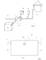
- a filtering device 20 and a method for separating floating contaminants and filtering rainwater from a roof drainage system 13 and a surface drainage 14, which in Fig. 1 are shown described.
- the filter device 20 would also be suitable for filtering water only from the roof drainage system 13 or only from the surface drainage 14.
- the filter device 20 has a water-filled water tank 5 in which, as in Fig. 2 illustrated, an inlet 1 for the water to be purified or to be filtered and opens to the opposite a channel outlet 2 to a channel 15 and at least one Nutzablauf 3 going to a sump or water tank 16.
- Both the inlet 1 and the drains 2 and 3 are located in an upper region of the water tank 5, whereby emptying of the water tank 5 is prevented.
- two utility processes 3 are provided which lead to two separate water reservoirs 16. It is possible to connect several and / or different water reservoirs 16 in parallel to the filter device 20. Of course, only one Nutzablauf 3 can be provided.
- the utility processes 3 to the water reservoirs 16 are transverse to the flow on a substantially same horizontal plane as the channel drain 2.
- the inlet 1 and the processes 2 and 3 are applied horizontally and at approximately the same level with an ideal maximum height offset of half a pipe diameter of the feed 1.
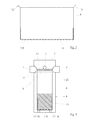
- a circumferential wall 22 having water tank 5 is in the FIGS. 4 and 5 to be recognized and in Fig. 7 arranged individually filter body 4, which, as from Fig. 5 shows increased at its the water tank 16 side facing and lower at its the channel port 2 facing side.
- a coarse screen 6 designed as a perforated plate is arranged in the upper region of the filter body 4, just below the water surface 10, preferably at a distance of 0.5-2 cm below the water surface 10.
- the Perforated plate 6 is used to prevent too deep sinking of larger objects such as Fallobst, seed pods, nuts, seeds, animals, etc. on the water surface 10 and to allow rinsing of these objects on the channel drain 2.
- the inlet 1 opens directly into an interior 21 of the filter body 4, so that it is ensured that water flowing into the filter device 4 from the roof drainage system 13 or the surface drainage 14 enters the filter device 20 and is filtered in the manner described below.
- the two utilizations 3 go from one outside of the filter body 4 located area of the water tank 5 from. As a result, only such water can leave the filter device 20, which has been filtered by the filter body 4, since the water has to flow through the filter body 4 in order to reach one of the utilizable operations 3.
- the two utility drains 3, generally the at least one utility drain 3, is disposed at a lower elevation than the sewer 2 or below the sewer 2, so that the filtered water preferably flows through the utility drains 3 into the reservoirs 16 and not through the sewer 2 lost in the channel 15.
- a perforated plate 7 is provided above the bottom of the water container 5 at the bottom of the filter body 4 as a support, support and support for a fine filter 8, in the form of a fine mesh, tile, grid or the like, on which a lime chalk layer 9 rests in the present case. which, however, could also be dispensed with.
- a lime chalk layer 9 in the filter body 4 on the fine filter 8 acid rainwater can be counteracted and the pH of the water can be increased, which protects sanitary items and installations.
- the perforated plate 7 and the fine filter 8 have filter openings 19, through which the water flowing into the interior 21 of the filter body 4 can leave the same to the outside of the filter body 4 and thus reach the water container 5.
- the Filter openings 19 are also in the lateral wall of the filter body 4 the Filter openings 19, wherein preferably the lime chalk layer 9 ends only above the filter openings 19, so that the water must always flow through the lime chalk layer 9 in order to leave the filter body 4 can.
- the circumferential wall or the side wall of the filter body 4 is closed at its upper, the inlet 1 and the channel outlet 2 facing area, that is not provided with the filter openings 19, and the filter openings 19th are provided only in its lower, the inlet 1 and channel drain 2 remote area.
- the filter openings 19 are provided exclusively at the bottom of the filter body 4, as for example in the reference to the in the FIGS. 11-18 described embodiment of the filter device 20 is the case.
- the water surface 10 is held by jigs 11, 12, which may be formed as sheets, plastic plates, concrete walls or the like, before the processes 2 and 3 at the level.
- the upper edge of the storage device 11 to the water reservoir 16 is located slightly lower than the upper edge of the storage device 12 to the channel outlet 2. In the present case, the difference is about 10% of the inner diameter of the pipe inlet 1.
- the filter body 4 protrudes on the channel expiry 2 facing Side over the storage device 12 and lies there.
- the filter body 4 conceals or closes the utility drains 3 of the water storage tank 16 facing sides by raised edges of the utility drains 3 to the water reservoir 16th
- the inner filter element 4, including the coarse filter 6, the perforated plate 7, the optional lime chalk layer 9 and the fine filter 8 can be removed completely from the water container 5 for cleaning and repair purposes or for filter replacement.
- folding handles, handles, hooks, straps or staplers can be attached to the filter body.
- the preparation of the water-filled water tank 5 can be plastered depending on the amount of water and size either composite materials, plastics, metal sheets, concrete or masonry and waterproof.
- preferably thin-walled materials such as plastics, metal sheets, sieves, tiles, fabrics or composite materials are used.
- the filter device 20 works much better when it is manufactured, mounted and set up very accurately, the setting preferably takes place with a spirit level of the water-filled water tank 5 with the inner filter body 4 in particular the stowage devices 11, 12.
- the functioning the filter device 20 is dependent on the state of the water surface 10 in the water-filled water container 5 and the filter body 4 contained therein.
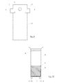
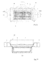
- FIGS. 11 to 18 show a further embodiment of the filter device 20, which preferably consists of a suitable plastic material and is prepared for example by a spin or injection molding process.
- the inlet 1 and the drains 2 and 3 are made in one piece with the water tank 5.
- the filter body 4 consists essentially of a part in which the perforated plate 7, optionally with the fine filter 8, and at a higher level the coarse sieve 6 are arranged at the bottom.
- the filter body 4 has a connected to the circumferential wall 22 of the water tank 5 cover 23, which is preferably sealed against the peripheral wall 22.
- the seal can be produced during the production of the filter device 20, as is possible, for example, by injection molding, or be formed by an additional seal 25, as may be the case with the centrifugal casting method.
- Fig. 16 is exemplified such a seal 25 located.
- the seal ie the point at which the cover 23 is sealed relative to the water tank 5, is preferably located below the highest point of the lower edge of the Nutzablaufs 3, which in Fig. 16 good to recognize and designated by the reference numeral 24. In this way it is ensured that the water surface 10 is always above the Grobsiebs 6, so that over the inlet 1 in the filter body 4 reaching dirt can not settle on the coarse screen 6 and remains dissolved in suspension or in the water.
- the lower edge 24 of the useful drain 3 thus determines the lowest possible water level in the water tank 5 or in the filter body. 4
- a method for filtering water from the roof drainage system 13 and / or the surface drainage 14 can be carried out, in which the water to be filtered via the inlet 1 into the water tank 5 and passed through the channel drain 2 to the channel 15th or via which at least one useful drain 3 is led to the at least one water reservoir 16 and in which the water conducted to the water reservoir 16 is passed through the filter body 4 arranged in the water tank 5.
Landscapes
- Engineering & Computer Science (AREA)
- Health & Medical Sciences (AREA)
- Life Sciences & Earth Sciences (AREA)
- Hydrology & Water Resources (AREA)
- Public Health (AREA)
- Water Supply & Treatment (AREA)
- Environmental & Geological Engineering (AREA)
- Sewage (AREA)
- Filtration Of Liquid (AREA)
Applications Claiming Priority (1)
| Application Number | Priority Date | Filing Date | Title |
|---|---|---|---|
| DE102010010263A DE102010010263A1 (de) | 2010-03-05 | 2010-03-05 | Vorrichtung und Verfahren zur Separation schwimmender Verunreinigungen und Filterung von Regenwasser aus Dachablaufsystemen und/oder Oberflächenentwässerungen |
Publications (1)
| Publication Number | Publication Date |
|---|---|
| EP2365140A2 true EP2365140A2 (fr) | 2011-09-14 |
Family
ID=44148803
Family Applications (1)
| Application Number | Title | Priority Date | Filing Date |
|---|---|---|---|
| EP11156972A Withdrawn EP2365140A2 (fr) | 2010-03-05 | 2011-03-04 | Dispositif de filtrage pour systèmes d'évacuation des eaux provenant des toitures |
Country Status (2)
| Country | Link |
|---|---|
| EP (1) | EP2365140A2 (fr) |
| DE (1) | DE102010010263A1 (fr) |
Cited By (3)
| Publication number | Priority date | Publication date | Assignee | Title |
|---|---|---|---|---|
| WO2016026479A1 (fr) * | 2014-08-22 | 2016-02-25 | Wisy Ag Haustechniksysteme, Filtertechnik | Filtre à eau de pluie |
| GB2547922A (en) * | 2016-03-03 | 2017-09-06 | Avon Water Systems Ltd | Improvements in or relating to filtering apparatus |
| CN108295551A (zh) * | 2018-03-13 | 2018-07-20 | 包宝金 | 一种环保型工业废水过滤装置 |
Family Cites Families (4)
| Publication number | Priority date | Publication date | Assignee | Title |
|---|---|---|---|---|
| DE3508885A1 (de) * | 1984-06-01 | 1985-12-05 | Bernhard 6143 Lorsch Hauptmann | Anlage zur wiederverwendung von abwaesser, insbesondere aus dem wasch-, dusch-, bad- bzw. kuechenbereich |
| DE8717458U1 (de) * | 1987-05-27 | 1989-02-23 | Racho, Dietmar, Dipl.-Ing., 5860 Iserlohn | Vorrichtung zur Abwasserrückführung |
| AT394031B (de) * | 1990-06-22 | 1992-01-27 | Stoiser & Wolschner | Vorrichtung zum behandeln von abwasser |
| DE202007008765U1 (de) * | 2007-06-22 | 2007-10-25 | Adolf Steinbach Steinindustrie Schotterwerke GmbH & Co. KG | Filtermaterial aus Kalksteinsand für Retentionsfilterbecken |
-
2010
- 2010-03-05 DE DE102010010263A patent/DE102010010263A1/de not_active Ceased
-
2011
- 2011-03-04 EP EP11156972A patent/EP2365140A2/fr not_active Withdrawn
Non-Patent Citations (1)
| Title |
|---|
| None |
Cited By (6)
| Publication number | Priority date | Publication date | Assignee | Title |
|---|---|---|---|---|
| WO2016026479A1 (fr) * | 2014-08-22 | 2016-02-25 | Wisy Ag Haustechniksysteme, Filtertechnik | Filtre à eau de pluie |
| CN106029200A (zh) * | 2014-08-22 | 2016-10-12 | 怀斯股份公司 家庭技术系统,过滤技术 | 雨水过滤器 |
| CN106029200B (zh) * | 2014-08-22 | 2017-11-07 | 怀斯股份公司家庭技术系统,过滤技术 | 雨水过滤器 |
| US10583377B2 (en) | 2014-08-22 | 2020-03-10 | Wisy Ag Haustechniksysteme, Filtertechnik | Rain water filter |
| GB2547922A (en) * | 2016-03-03 | 2017-09-06 | Avon Water Systems Ltd | Improvements in or relating to filtering apparatus |
| CN108295551A (zh) * | 2018-03-13 | 2018-07-20 | 包宝金 | 一种环保型工业废水过滤装置 |
Also Published As
| Publication number | Publication date |
|---|---|
| DE102010010263A1 (de) | 2011-09-08 |
Similar Documents
| Publication | Publication Date | Title |
|---|---|---|
| DE102011001356B4 (de) | Versickerungsanordnung | |
| EP2085527B1 (fr) | Installation d'exploitation d'eau de pluie | |
| DE202009010367U1 (de) | Vorrichtung zur Trennung von Regenwasser von chemisch, biologisch und/oder toxisch belasteten Abwässern | |
| DE29502895U1 (de) | Regenwasserfiltereinrichtung | |
| EP0565921A2 (fr) | Installation de traitement et de manutention d'eau pluviale pour l'utilisation comme eau industrielle ou de traitement en vue d'infiltration ou d'introduction dans un évacuateur | |
| DE10143985C1 (de) | Rinnenabschnitt zur Herstellung einer Rinne zur Aufnahme von Oberflächenwasser | |
| DE102014012288A1 (de) | Regenwasserfilter | |
| EP2365140A2 (fr) | Dispositif de filtrage pour systèmes d'évacuation des eaux provenant des toitures | |
| EP0699255B1 (fr) | Construction prefabriquee en beton arme ou dans un materiau equivalent | |
| AT391158B (de) | Einrichtung zum ableiten von regenwasser u.dgl. | |
| DE69621095T2 (de) | Unterirdischer Pufferbehälter zum Lagern und Behandeln von Regenwasser | |
| DE202008011014U1 (de) | Verbesserter Straßen- oder Bodeneinlauf mit Rückhalteeinrichtung für Leichtflüssigkeiten | |
| DE202007011126U1 (de) | Sedimentationsanlage | |
| EP0767278B1 (fr) | Système de caniveau pour l'infiltration d'eau | |
| WO2010022704A2 (fr) | Citerne pourvue d'un filtre à eau de pluie dans l'arrivée et boîtier de filtre pour filtre à eau de pluie | |
| DE19647351A1 (de) | Regenwasserableitvorrichtung, verwendbar in einem Regenwassersammelsystem und Verfahren zum Ableiten von Regenwasser aus Fallrohren | |
| DE19509466A1 (de) | Speicher für Flüssigkeiten | |
| DE19714739A1 (de) | Regenwasserspeicher | |
| EP1002905A2 (fr) | Système collecteur et distributeur pour eaux de pluie à haute pression hydrostatique | |
| DE102017108820A1 (de) | Filteranlage | |
| DE19860860A1 (de) | Regenwasser-Filteranlage | |
| DE102021122297B4 (de) | Wassertank | |
| DE29907872U1 (de) | Filterkörper für Kleinkläranlagen | |
| EP0679209B1 (fr) | Reservoir | |
| EP2127716B1 (fr) | Dispositif de filtre pour récipient de collecte d'eau de pluie |
Legal Events
| Date | Code | Title | Description |
|---|---|---|---|
| PUAI | Public reference made under article 153(3) epc to a published international application that has entered the european phase |
Free format text: ORIGINAL CODE: 0009012 |
|
| AK | Designated contracting states |
Kind code of ref document: A2 Designated state(s): AL AT BE BG CH CY CZ DE DK EE ES FI FR GB GR HR HU IE IS IT LI LT LU LV MC MK MT NL NO PL PT RO RS SE SI SK SM TR |
|
| AX | Request for extension of the european patent |
Extension state: BA ME |
|
| STAA | Information on the status of an ep patent application or granted ep patent |
Free format text: STATUS: THE APPLICATION IS DEEMED TO BE WITHDRAWN |
|
| 18D | Application deemed to be withdrawn |
Effective date: 20141001 |