EP0565979A1 - Dispositif d'enduction pour des bandes de papier en carton - Google Patents
Dispositif d'enduction pour des bandes de papier en carton Download PDFInfo
- Publication number
- EP0565979A1 EP0565979A1 EP93105561A EP93105561A EP0565979A1 EP 0565979 A1 EP0565979 A1 EP 0565979A1 EP 93105561 A EP93105561 A EP 93105561A EP 93105561 A EP93105561 A EP 93105561A EP 0565979 A1 EP0565979 A1 EP 0565979A1
- Authority
- EP
- European Patent Office
- Prior art keywords
- web
- roller
- upper roller
- coating
- lower roller
- Prior art date
- Legal status (The legal status is an assumption and is not a legal conclusion. Google has not performed a legal analysis and makes no representation as to the accuracy of the status listed.)
- Withdrawn
Links
Images
Classifications
-
- D—TEXTILES; PAPER
- D21—PAPER-MAKING; PRODUCTION OF CELLULOSE
- D21H—PULP COMPOSITIONS; PREPARATION THEREOF NOT COVERED BY SUBCLASSES D21C OR D21D; IMPREGNATING OR COATING OF PAPER; TREATMENT OF FINISHED PAPER NOT COVERED BY CLASS B31 OR SUBCLASS D21G; PAPER NOT OTHERWISE PROVIDED FOR
- D21H23/00—Processes or apparatus for adding material to the pulp or to the paper
- D21H23/02—Processes or apparatus for adding material to the pulp or to the paper characterised by the manner in which substances are added
- D21H23/22—Addition to the formed paper
- D21H23/52—Addition to the formed paper by contacting paper with a device carrying the material
- D21H23/56—Rolls
- D21H23/58—Details thereof, e.g. surface characteristics, peripheral speed
Definitions
- the invention relates to a coating device according to the preamble of claim 1.
- a coating device is known from DE 40 14 647 A1. It is provided that a roller is arranged below a roller with a relatively small diameter to the first roller, the lower roller on one side with respect to the vertical with a nozzle applicator and on the other side an applicator with one of a doctor element and its holder formed swamp is arranged. On the first side - again with respect to the vertical - of the upper roller there is also an application unit with a sump, which is formed by a doctor element and its holder. Different coating processes can be carried out with this device, however, a very different path guidance is necessary in each case.
- the web is fed from the basement and from another side of the lower roll than for the other coating case, a press nip formed between the two rolls.
- an at least partially pivotable operator platform for the applicator unit of the upper roller and a pivotable holder for a deflection roller in the region of the upper roller or its applicator unit are also provided. Nevertheless, the variability of the necessary strokes is not yet satisfactory.
- the object of the invention is, in contrast, a large variability of the coating options in one Coating device that consists of two rollers to create with little additional effort with a relatively simple cable guide.
- a coating on one or both sides should be possible with or without strong pressure (pressure of the rollers on the coated web).
- the solution according to the invention is particularly aimed at using the rollers and applicators in a coating intended for paper of very low quality in such a way that first the coating of the lateral surface of the roller in question in its area not wrapped by the web and only then Transfer to the web is done.
- the lower roller is preferably approximated to the upper one except for a relatively narrow coating gap, or is pressed on in the case of glues.
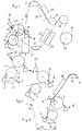
- the rollers 1 and 2 are arranged essentially one above the other, with the lower roller 2 being arranged somewhat offset laterally with respect to the upper and to the web B against the direction of web travel (see arrow).
- the coating composition via a nozzle applicator 3, which has an application chamber 13 and a doctor element 12, here indicated as a doctor blade.
- This squeegee element could also be a doctor blade, and the squeegee rod could have a circumferential groove, for example a wire wrap.
- the application unit 8 of the upper roller which is provided on the other side with respect to the vertical V like the application unit of the lower roller.
- an application unit 15 is assigned to the upper roller 1, in which a sump 20 with a preferably free liquid level for coating composition is formed by means of a doctor element 16 and its carrier 17.
- This sump can be formed both from coating slip with a low pigment content (solids content generally less than 45%) and glue, possibly also heavily diluted with water, or water.
- the path of the web is here such that, after leaving the application units, the web is fed obliquely downward to a non-contact air jet path deflection device 32. This redirects the web upwards at an angle of less than 120 ° (here about 92 °).
- One of the upper applicators can be used in conjunction with the applicator of the lower roller for double-sided application to the web.
- the nozzle applicator 3 of the lower roller 2 can also either apply glue or a coating compound with pigment content. If the "sump" applicator 15 of the upper roller is used, the other applicator 8 thereof can be used to clean the roller 1 by means of a doctor blade or a smooth doctor rod.
- the lower roller 2 is removed from the upper roller 1 and the web is guided only along the upper roller 1.
- This web guide is mainly used to coat the underside of the web with the coating unit 8, the coating slip has a pigment content between 30 and 70% and an order of at least 5 g / m2, in the majority of factories at least 10 g / m2.
- the other side of the web can be lightly pigmented with the "sump" applicator 15 or glued with a large amount of water to improve the flatness of the web.
- a doctor blade or a smooth doctor rod can also be used here to clean the roller 1.
- the web is fed to a likewise non-contact air jet web deflection device 31, which preferably deflects the web by an angle of more than 125 ° (here about 133 °, see FIG. 1).
- This web guide can also be the only one in all cases, especially if the "coating unit” 9 is arranged very far down on roller 1 and roller 2 in relation to roller 1 so that the angle a is on the other side of the vertical V or is very small.
- the pre-metering quantity on the lower roller can be regulated by the set web tension. The same can be done with respect to the upper roller 1 and then the applicator.
- the applicators can have doctor blades or doctor blades with a smooth or grooved surface.
- lower roll 2 a hard cover between 0 and 20 P u. J and upper roller 1 between 20 and 70 P u. J (after P ucey and J ones). Basically, a hardness between 0 and 90 P u. J possible.
- the lower roller is to be arranged so that when it comes into contact with or forms an application nip to the upper roller 1, its contact point or the application nip removes a circumferential angle a between 10 ° and 70 °, preferably 15 ° - 40 °, from the deepest point of the upper roller is.
- This has the advantage that the wrap angles of the rollers 2 and 1 through the web c (Fig. 1) and d (Fig. 4) are quite small. You have to take into account that the airturn 32 and the heating device take up a lot of space and so - in the manner according to the invention - enough space for the deflecting rollers 40 and 41 - there is still enough space, although there is also space for the stands 37 of the application unit 8 must be present.
- the web is coated on the two or three consecutive application units within 0.15 seconds at the latest.
- Roller 2 is advantageously designed with controlled deflection compensation, such as in DE 30 11 669, DE 29 38 427, DE 29 42 002 or DE 31 01 115. Both rollers can also be advantageously designed for temperature control.
- Fig. 1 the web guide belonging to Fig. 2 is also indicated, from which it can be seen that after deflecting rollers 33 and 34 the web path is in all cases - via cylinder 36 - advantageously identical.
- the heating devices 26, 27, 28, 29 for drying the web can be of any design.
- Roll 34 can also be a small drying cylinder - a so-called baby cylinder.
- a scooping roller 31 which dips into a trough 37, is also indicated by dash-dotted lines and applies the coating slip to the roller shell instead of the coating unit 3.
- Fig. 4 shows a solution for extreme demands.
- the top can be painted with the same aggreat. To do this, the direction of rotation of roller 1 must be reversed. This now acts as a guide roller.
- the optimal dryer 38 can be a radiation dryer (e.g. IR el / gas) or combination dryer (IR + air) when the web is straight. This dryer is advantageously designed with a slight curvature as a "pseudo" air turn, so that the running-in conditions of the contactless web guide at 31 remain unchanged compared to FIGS. 2, 4 and 3.
- the web guidance is changed by deflection rollers 40-43.
- Nozzle applicators of a generally customary type are known from US 4,250,211.
- Sump applicators - with a free liquid level - are known from DE 39 22 535 A1 or US 2,970,564, of which the former also shows a doctor blade with thread-like "circumferential grooves" (see also US 3,387,585).
- the lower roller 2 is advantageous - in particular in the case of a scoop roller application (roller 39, FIG. 2) - but also otherwise, as a deflection-controlled roller.
- Both rollers 1 and 2 should be coolable and temperature-controllable for best coating results.
Landscapes
- Coating Apparatus (AREA)
- Paper (AREA)
Applications Claiming Priority (2)
| Application Number | Priority Date | Filing Date | Title |
|---|---|---|---|
| DE4211401A DE4211401A1 (de) | 1992-04-04 | 1992-04-04 | Beschichtungseinrichtung für Bahnen aus Papier oder Karton |
| DE4211401 | 1992-04-04 |
Publications (1)
| Publication Number | Publication Date |
|---|---|
| EP0565979A1 true EP0565979A1 (fr) | 1993-10-20 |
Family
ID=6456122
Family Applications (1)
| Application Number | Title | Priority Date | Filing Date |
|---|---|---|---|
| EP93105561A Withdrawn EP0565979A1 (fr) | 1992-04-04 | 1993-04-03 | Dispositif d'enduction pour des bandes de papier en carton |
Country Status (3)
| Country | Link |
|---|---|
| US (1) | US5401314A (fr) |
| EP (1) | EP0565979A1 (fr) |
| DE (1) | DE4211401A1 (fr) |
Cited By (4)
| Publication number | Priority date | Publication date | Assignee | Title |
|---|---|---|---|---|
| DE29511088U1 (de) * | 1995-07-08 | 1995-09-14 | Voith Sulzer Papiermaschinen GmbH, 89522 Heidenheim | Vorrichtung zum Herstellen einer gestrichenen Materialbahn |
| DE4438445A1 (de) * | 1994-10-28 | 1996-05-02 | Jagenberg Papiertech Gmbh | Vorrichtung zum Beschichten einer Papier- oder Kartonbahn |
| DE19743246A1 (de) * | 1997-09-30 | 1999-04-01 | Voith Sulzer Papiertech Patent | Kombinations-Auftragsvorrichtung |
| DE10355686A1 (de) * | 2003-11-28 | 2005-06-23 | Voith Paper Patent Gmbh | Papiermaschine |
Families Citing this family (9)
| Publication number | Priority date | Publication date | Assignee | Title |
|---|---|---|---|---|
| DE4341566B4 (de) * | 1993-12-07 | 2005-03-10 | Heidelberger Druckmasch Ag | Trennmittelschichten zum Oberflächenschutz frisch bedruckter Bogen und Vorrichtung zum Beschichten der frisch bedruckten Bogen mit der Trennmittelschicht |
| DE4416399C2 (de) * | 1994-05-09 | 1999-04-01 | Voith Gmbh J M | Trocknungsvorrichtung für eine laufende Materialbahn |
| DE4420242A1 (de) * | 1994-06-10 | 1995-01-05 | Voith Gmbh J M | Einrichtung zur wahlweisen Behandlung einer laufenden Bahn |
| DE9409820U1 (de) * | 1994-06-17 | 1994-09-01 | J.M. Voith AG, St. Pölten | Vorrichtung zum Auftragen von mindestens einem flüssigen Medium auf eine laufende Materialbahn |
| DE29508421U1 (de) | 1995-05-20 | 1995-09-14 | Voith Sulzer Papiermaschinen GmbH, 89522 Heidenheim | Stationäre Gleitleiste |
| DE19827030A1 (de) * | 1998-06-17 | 1999-12-23 | Voith Sulzer Papiertech Patent | Auftragsvorrichtung |
| GB0523013D0 (en) * | 2005-11-11 | 2005-12-21 | Conductive Inkjet Tech Ltd | Handling of flexible planar material |
| FI128981B (en) | 2018-07-27 | 2021-04-30 | Voith Patent Gmbh | Method and apparatus for applying starch |
| EP3988713B1 (fr) | 2020-10-23 | 2023-11-01 | Valmet Technologies Oy | Procédé de traitement d'une bande de matière fibreuse et système de traitement pour le traitement d'une bande de matière fibreuse |
Citations (3)
| Publication number | Priority date | Publication date | Assignee | Title |
|---|---|---|---|---|
| EP0142925A1 (fr) * | 1983-09-26 | 1985-05-29 | The Black Clawson Company | Rouleau enducteur de précision |
| DE3701670A1 (de) * | 1987-01-22 | 1988-08-04 | Voith Gmbh J M | Auftragswerk zur beschichtung und befeuchtung laufender warenbahnen |
| DE3922535A1 (de) * | 1988-07-27 | 1990-02-01 | Voith Gmbh J M | Auftragseinrichtung zur beschichtung laufender warenbahnen sowie verfahren zur beschichtung |
Family Cites Families (4)
| Publication number | Priority date | Publication date | Assignee | Title |
|---|---|---|---|---|
| US2970564A (en) * | 1955-12-23 | 1961-02-07 | Champion Paper & Fibre Co | Apparatus for coating paper |
| SE427805B (sv) * | 1978-12-20 | 1983-05-09 | Inventing Ab | Sett och anleggning for valfri behandling, sasom ensidig eller tvasidig bestrykning, impregnering eller ytlimning av en lopande bana. |
| DE4002256A1 (de) * | 1990-01-26 | 1991-08-01 | Voith Gmbh J M | Beschichtungsverfahren und auftragseinrichtung zur beschichtung laufender warenbahnen aus papier oder karton |
| DE4014647C2 (de) * | 1990-05-08 | 1995-03-30 | Voith Gmbh J M | Einrichtung zum Auftragen einer Beschichtung auf eine laufende Warenbahn |
-
1992
- 1992-04-04 DE DE4211401A patent/DE4211401A1/de not_active Withdrawn
-
1993
- 1993-04-03 EP EP93105561A patent/EP0565979A1/fr not_active Withdrawn
- 1993-04-05 US US08/042,544 patent/US5401314A/en not_active Expired - Fee Related
Patent Citations (3)
| Publication number | Priority date | Publication date | Assignee | Title |
|---|---|---|---|---|
| EP0142925A1 (fr) * | 1983-09-26 | 1985-05-29 | The Black Clawson Company | Rouleau enducteur de précision |
| DE3701670A1 (de) * | 1987-01-22 | 1988-08-04 | Voith Gmbh J M | Auftragswerk zur beschichtung und befeuchtung laufender warenbahnen |
| DE3922535A1 (de) * | 1988-07-27 | 1990-02-01 | Voith Gmbh J M | Auftragseinrichtung zur beschichtung laufender warenbahnen sowie verfahren zur beschichtung |
Cited By (4)
| Publication number | Priority date | Publication date | Assignee | Title |
|---|---|---|---|---|
| DE4438445A1 (de) * | 1994-10-28 | 1996-05-02 | Jagenberg Papiertech Gmbh | Vorrichtung zum Beschichten einer Papier- oder Kartonbahn |
| DE29511088U1 (de) * | 1995-07-08 | 1995-09-14 | Voith Sulzer Papiermaschinen GmbH, 89522 Heidenheim | Vorrichtung zum Herstellen einer gestrichenen Materialbahn |
| DE19743246A1 (de) * | 1997-09-30 | 1999-04-01 | Voith Sulzer Papiertech Patent | Kombinations-Auftragsvorrichtung |
| DE10355686A1 (de) * | 2003-11-28 | 2005-06-23 | Voith Paper Patent Gmbh | Papiermaschine |
Also Published As
| Publication number | Publication date |
|---|---|
| DE4211401A1 (de) | 1993-10-07 |
| US5401314A (en) | 1995-03-28 |
Similar Documents
| Publication | Publication Date | Title |
|---|---|---|
| AT392426B (de) | Leimpresse mit zwei zueinander parallelen presswalzen | |
| EP0706592B1 (fr) | Procede et dispositif pour produire des bandes de papier couchees deux faces | |
| EP0352582B2 (fr) | Procédé de couchage de bandes défilantes en papier ou en carton | |
| EP0670004B1 (fr) | Procede et dispositif permettant d'effectuer le couchage d'une bande continue de materiau | |
| EP1964971A2 (fr) | Procédé de fabrication d'une bande de matière fibreuse revêtue, en particulier de papier ou de carton | |
| DE69004595T2 (de) | Verfahren zum Auftragen von mikrokapselhaltigen Zusammensetzungen auf Papier. | |
| DE4014647C2 (de) | Einrichtung zum Auftragen einer Beschichtung auf eine laufende Warenbahn | |
| DE19704858B4 (de) | Verfahren und Vorrichtung zum Herstellen beidseitig gestrichener Papierbahnen | |
| DE69401228T2 (de) | Verfahren und Vorrichtung zum Begrenzen der Beschichtungsbreite und/oder zur Verhinderung von Rollenschäden in der Beschichtung oder Oberflächenleimung von Papier oder von gleichen Bahnmaterial | |
| DE4211401A1 (de) | Beschichtungseinrichtung für Bahnen aus Papier oder Karton | |
| DE19545408C2 (de) | Verfahren zur Oberflächenveredelung einer Kartonbahn | |
| DE4218596C2 (de) | Streicheinrichtung zum indirekten Auftragen von Streichfarbe auf eine Papier- oder Kartonbahn | |
| DE3440634C2 (de) | Einrichtung zur beidseitigen Beschichtung laufender Warenbahnen | |
| DE4302435A1 (en) | Paper web coating appts. - has smoother against side of web in free path after leaving gap between applicator rollers | |
| DE69618144T2 (de) | Verfahren und Zusammenbau zur Beschichtung einer Papierbahn | |
| DE3139739A1 (de) | "bahnbeschichtungsvorrichtung" | |
| EP0812957A1 (fr) | Procédé et dispositif pour le couchage d'une bande mouvante | |
| AT506528B1 (de) | Verfahren und anordnung zur herstellung von mehrschichtig gestrichenem papier | |
| EP0050269B1 (fr) | Procédé et dispositif pour vernir des corps cylindriques creux tels que corps de boîte tout autour de leur pourtour | |
| EP0812958A1 (fr) | Dispositif pour l'application de deux couches dans l'ordre successif de médias liquides ou pâteux sur un cÔté d'une bande de material en marche | |
| WO1994015021A1 (fr) | Dispositif permettant d'appliquer simultanement du liquide sur les deux cotes d'une bande de materiau et procede d'application d'un liquide sur une bande de materiau a l'aide dudit dispositif | |
| DE3439227A1 (de) | Auftragswerk fuer eine wellpappenanlage | |
| DE102005035317A1 (de) | Auftragsverfahren | |
| AT500687B1 (de) | Verfahren und vorrichtung zum beschichten von pappe | |
| DE9303814U1 (de) | Auftragungsvorrichtung |
Legal Events
| Date | Code | Title | Description |
|---|---|---|---|
| PUAI | Public reference made under article 153(3) epc to a published international application that has entered the european phase |
Free format text: ORIGINAL CODE: 0009012 |
|
| AK | Designated contracting states |
Kind code of ref document: A1 Designated state(s): AT CH DE FR GB IT LI SE |
|
| 17P | Request for examination filed |
Effective date: 19940117 |
|
| 17Q | First examination report despatched |
Effective date: 19941227 |
|
| 18W | Application withdrawn |
Withdrawal date: 19951223 |