EP0566088B1 - Lageranordnung zur Verwendung in einem Spaltrohrmotor - Google Patents
Lageranordnung zur Verwendung in einem Spaltrohrmotor Download PDFInfo
- Publication number
- EP0566088B1 EP0566088B1 EP93106066A EP93106066A EP0566088B1 EP 0566088 B1 EP0566088 B1 EP 0566088B1 EP 93106066 A EP93106066 A EP 93106066A EP 93106066 A EP93106066 A EP 93106066A EP 0566088 B1 EP0566088 B1 EP 0566088B1
- Authority
- EP
- European Patent Office
- Prior art keywords
- bearing
- bearing housing
- thrust
- radial
- motor frame
- Prior art date
- Legal status (The legal status is an assumption and is not a legal conclusion. Google has not performed a legal analysis and makes no representation as to the accuracy of the status listed.)
- Expired - Lifetime
Links
Images





Classifications
-
- F—MECHANICAL ENGINEERING; LIGHTING; HEATING; WEAPONS; BLASTING
- F04—POSITIVE - DISPLACEMENT MACHINES FOR LIQUIDS; PUMPS FOR LIQUIDS OR ELASTIC FLUIDS
- F04D—NON-POSITIVE-DISPLACEMENT PUMPS
- F04D29/00—Details, component parts, or accessories
- F04D29/04—Shafts or bearings, or assemblies thereof
- F04D29/046—Bearings
- F04D29/047—Bearings hydrostatic; hydrodynamic
-
- F—MECHANICAL ENGINEERING; LIGHTING; HEATING; WEAPONS; BLASTING
- F04—POSITIVE - DISPLACEMENT MACHINES FOR LIQUIDS; PUMPS FOR LIQUIDS OR ELASTIC FLUIDS
- F04D—NON-POSITIVE-DISPLACEMENT PUMPS
- F04D13/00—Pumping installations or systems
- F04D13/02—Units comprising pumps and their driving means
- F04D13/06—Units comprising pumps and their driving means the pump being electrically driven
- F04D13/0606—Canned motor pumps
- F04D13/0613—Special connection between the rotor compartments
-
- F—MECHANICAL ENGINEERING; LIGHTING; HEATING; WEAPONS; BLASTING
- F04—POSITIVE - DISPLACEMENT MACHINES FOR LIQUIDS; PUMPS FOR LIQUIDS OR ELASTIC FLUIDS
- F04D—NON-POSITIVE-DISPLACEMENT PUMPS
- F04D29/00—Details, component parts, or accessories
- F04D29/04—Shafts or bearings, or assemblies thereof
- F04D29/046—Bearings
- F04D29/0465—Ceramic bearing designs
-
- F—MECHANICAL ENGINEERING; LIGHTING; HEATING; WEAPONS; BLASTING
- F16—ENGINEERING ELEMENTS AND UNITS; GENERAL MEASURES FOR PRODUCING AND MAINTAINING EFFECTIVE FUNCTIONING OF MACHINES OR INSTALLATIONS; THERMAL INSULATION IN GENERAL
- F16C—SHAFTS; FLEXIBLE SHAFTS; ELEMENTS OR CRANKSHAFT MECHANISMS; ROTARY BODIES OTHER THAN GEARING ELEMENTS; BEARINGS
- F16C17/00—Sliding-contact bearings for exclusively rotary movement
- F16C17/04—Sliding-contact bearings for exclusively rotary movement for axial load only
-
- F—MECHANICAL ENGINEERING; LIGHTING; HEATING; WEAPONS; BLASTING
- F16—ENGINEERING ELEMENTS AND UNITS; GENERAL MEASURES FOR PRODUCING AND MAINTAINING EFFECTIVE FUNCTIONING OF MACHINES OR INSTALLATIONS; THERMAL INSULATION IN GENERAL
- F16C—SHAFTS; FLEXIBLE SHAFTS; ELEMENTS OR CRANKSHAFT MECHANISMS; ROTARY BODIES OTHER THAN GEARING ELEMENTS; BEARINGS
- F16C27/00—Elastic or yielding bearings or bearing supports, for exclusively rotary movement
- F16C27/06—Elastic or yielding bearings or bearing supports, for exclusively rotary movement by means of parts of rubber or like materials
- F16C27/063—Sliding contact bearings
-
- F—MECHANICAL ENGINEERING; LIGHTING; HEATING; WEAPONS; BLASTING
- F16—ENGINEERING ELEMENTS AND UNITS; GENERAL MEASURES FOR PRODUCING AND MAINTAINING EFFECTIVE FUNCTIONING OF MACHINES OR INSTALLATIONS; THERMAL INSULATION IN GENERAL
- F16C—SHAFTS; FLEXIBLE SHAFTS; ELEMENTS OR CRANKSHAFT MECHANISMS; ROTARY BODIES OTHER THAN GEARING ELEMENTS; BEARINGS
- F16C33/00—Parts of bearings; Special methods for making bearings or parts thereof
- F16C33/02—Parts of sliding-contact bearings
- F16C33/04—Brasses; Bushes; Linings
- F16C33/043—Sliding surface consisting mainly of ceramics, cermets or hard carbon, e.g. diamond like carbon [DLC]
-
- F—MECHANICAL ENGINEERING; LIGHTING; HEATING; WEAPONS; BLASTING
- F16—ENGINEERING ELEMENTS AND UNITS; GENERAL MEASURES FOR PRODUCING AND MAINTAINING EFFECTIVE FUNCTIONING OF MACHINES OR INSTALLATIONS; THERMAL INSULATION IN GENERAL
- F16C—SHAFTS; FLEXIBLE SHAFTS; ELEMENTS OR CRANKSHAFT MECHANISMS; ROTARY BODIES OTHER THAN GEARING ELEMENTS; BEARINGS
- F16C33/00—Parts of bearings; Special methods for making bearings or parts thereof
- F16C33/02—Parts of sliding-contact bearings
- F16C33/04—Brasses; Bushes; Linings
- F16C33/06—Sliding surface mainly made of metal
- F16C33/08—Attachment of brasses, bushes or linings to the bearing housing
-
- H—ELECTRICITY
- H02—GENERATION; CONVERSION OR DISTRIBUTION OF ELECTRIC POWER
- H02K—DYNAMO-ELECTRIC MACHINES
- H02K5/00—Casings; Enclosures; Supports
- H02K5/04—Casings or enclosures characterised by the shape, form or construction thereof
- H02K5/12—Casings or enclosures characterised by the shape, form or construction thereof specially adapted for operating in liquid or gas
- H02K5/128—Casings or enclosures characterised by the shape, form or construction thereof specially adapted for operating in liquid or gas using air-gap sleeves or air-gap discs
-
- H—ELECTRICITY
- H02—GENERATION; CONVERSION OR DISTRIBUTION OF ELECTRIC POWER
- H02K—DYNAMO-ELECTRIC MACHINES
- H02K5/00—Casings; Enclosures; Supports
- H02K5/04—Casings or enclosures characterised by the shape, form or construction thereof
- H02K5/16—Means for supporting bearings, e.g. insulating supports or means for fitting bearings in the bearing-shields
- H02K5/167—Means for supporting bearings, e.g. insulating supports or means for fitting bearings in the bearing-shields using sliding-contact or spherical cap bearings
- H02K5/1672—Means for supporting bearings, e.g. insulating supports or means for fitting bearings in the bearing-shields using sliding-contact or spherical cap bearings radially supporting the rotary shaft at both ends of the rotor
-
- F—MECHANICAL ENGINEERING; LIGHTING; HEATING; WEAPONS; BLASTING
- F16—ENGINEERING ELEMENTS AND UNITS; GENERAL MEASURES FOR PRODUCING AND MAINTAINING EFFECTIVE FUNCTIONING OF MACHINES OR INSTALLATIONS; THERMAL INSULATION IN GENERAL
- F16C—SHAFTS; FLEXIBLE SHAFTS; ELEMENTS OR CRANKSHAFT MECHANISMS; ROTARY BODIES OTHER THAN GEARING ELEMENTS; BEARINGS
- F16C2380/00—Electrical apparatus
- F16C2380/26—Dynamo-electric machines or combinations therewith, e.g. electro-motors and generators
Definitions
- the present invention relates to a bearing device for use in a canned motor, and more particularly to a bearing device comprising a cartridge-type bearing for use in a canned motor.
- GB-A-1 070 063 shows a wet motor pump having a sealed motor casing and a pump shaft. Said casing having an end plate fixed thereto with a tubular extension supporting a sleeve bearing.
- US-A-2 993 131 shows an electric motor comprising a rotor, a stator and two bearing cartridges for supportig said rotor coaxially in a tubular member, each cartridge being in the shape of two cylindrical portions of unequal diameter with an intermediate flange, the cylindrical cartridge portion with the larger diameter engaging the end of the tubular member with the flanges abutting the ends of said member, the cylindrical portions with the smaller diameter standing outward and having circumferential grooves and thin rings of resilient material mounted in said grooves by means of which the bearing cartridges and the motor are supported in a frame.
- a canned-motor pump has a pump casing for housing a canned motor therein.
- a canned-motor pump circulates some of the fluid being pumped to lubricate the bearings of the canned motor and also cool the canned motor.
- the bearings of the canned motor generally include two radial bearings of plain metal for supporting a motor rotor at its opposite ends and two thrust bearings of plain metal for bearing thrust loads applied to both side ends in opposite axial directions. It is important that these bearings be highly accurate both individually and relatively to each other, i.e., with respect to mutual concentricity, perpendicularity to the motor axis, axial end play, and other factors. To meet such accuracy requirements, it is necessary for the bearings to be structured and shaped for easily achieving a desired level of accuracy, so that the bearings can be machined and assembled with accuracy.
- a canned motor has a rotor 60 rotatably supported by radial bearings 62, 63 on both ends thereof.
- the rotor 60 has a shaft 61 on which thrust disks 64, 65 are fixedly mounted at the both ends, respectively.
- Thrust bearings 66, 67 are fixed to respective axially outer surfaces of the respective thrust discs 64, 65.
- the canned motor also has a motor frame 68 to which a thrust bearing 69 is fixed near the output side end, the thrust bearing 66 being rotatable with respect to, and disposed in axially confronting relationship to, the thrust bearing 69.
- the radial bearing 63 is supported in a bearing housing 70 that is fastened to the motor frame 68 near the other end.
- the thrust bearing 67 is rotatable with respect to, and disposed in axially confronting relationship to, the radial bearing 63.
- the motor frame 68 and other parts fixedly coupled thereto serve as a motor stator.
- the canned motor is incorporated in a pump for delivering a liquid. If such a liquid contains a slurry, the clearance between the sliding surfaces of each of the radial bearings 62, 63 should be small to prevent the slurry from entering the radial bearings 62, 63.
- the thrust bearings 66, 67, 69 are required to have an optimum axial end play.
- the canned motor is required to accurately define a dimension A (see FIG. 13(a)), i.e., the distance between the axially outer surfaces of the rotatable thrust bearings 66, 67, and a dimension G (see FIG. 13(b)), i.e., the distance between the axially inner surfaces of the stationary thrust bearing 69 and the radial bearing 63.
- a dimension A i.e., the distance between the axially outer surfaces of the rotatable thrust bearings 66, 67
- a dimension G i.e., the distance between the axially inner surfaces of the stationary thrust bearing 69 and the radial bearing 63.
- the shaft 61 which is a relatively large part of the rotor, cannot easily be machined because its large dimension has to be defined with the same accuracy as the other parts.
- stator which is also a relatively large part of the motor, cannot easily be machined because its large dimension has to be defined with the same accuracy as the other parts and also because the stator itself requires a high machining finish.
- the thrust bearings 66, 67, 69 are positioned on the opposite ends of the shaft 61, the actual axial end play in those thrust bearings 66, 67, 69 can be determined only after the rotor is actually assembled in the stator. In the event that the actual axial end play is fqund to be inappropriate, the rotor has to be disassembled from the stator, the thrust bearings 66, 67,69 and other parts have to be machined or adjusted, and the rotor has to be assembled in the stator again. Such disassembling, adjusting, and assembling processes have to be repeated until the proper axial end play is achieved.
- FIG. 1 shows in cross section a full-circumferential flow in-line pump having a canned motor which incorporates a bearing device according to an embodiment of the present invention.
- the in-line pump generally comprises a suction-side casing 1, a discharge-side casing 5, and an outer cylinder 9 interconnecting the suction-side casing 1 and the discharge-side casing 5.
- the suction-side casing 1, the discharge-side casing 5, and the outer cylinder 9 are in the form of sheets such as stainless steel pressed to shape by a deep drawing.
- the suction-side casing 1, the discharge-side casing 5, and the outer cylinder 9 have respective flanges 1a, 5a, 9a, 9b extending radially outwardly from open ends thereof.
- the adjacent flanges 1a, 9a of the suction-side casing 1 and the outer cylinder 9 are clamped by flanges 20 in the form of castings such as iron castings, and securely fastened to each other by bolts 45 which join the flanges 20.
- the adjacent flanges 5a, 9b of the discharge-side casing 5 and the outer cylinder 9 are clamped by flanges 21 in the form of castings such as iron castings, and securely fastened to each other by bolts 45 which join the flanges 21.
- Each of the flanges 20, 21 is composed of two separable flange members.
- the suction-side casing 1, the discharge-side casing 5, and the outer cylinder 9 jointly serve as a pump casing, which houses a canned motor 22.
- the suction-side casing 1 comprises a frustoconical body 2 and a cylindrical suction nozzle 3 extending axially into a suction region from the frustoconical body 2.
- the discharge-side casing 5 comprises a frustoconical body 6 and a cylindrical discharge nozzle 7 extending axially into a discharge region from the frustoconical body 6.
- the suction-side casing 5 and the discharge-side casing 6 are identical in dimension and shape to each other.
- the suction nozzle 3 and the discharge nozzle 7 define respective suction and discharge ports that are positioned axially in line with each other.
- the full-circumferential flow in-line pump also has an inner casing 10 disposed radially inwardly of the suction-side casing 1.
- the inner casing 10 comprises a cup-shaped body 11 and a cylindrical suction portion 12 extending axially from the cup-shaped body 11 into the suction region.
- a guide device 13, which defines guide vanes or a volute, is mounted on a radially inner surface of the cup-shaped body 11 of the inner casing 10.
- the guide device 13 is fitted over a motor frame 23 of the canned motor 22 in a socket-and-spigot joint.
- the motor frame 23 of the canned motor 22 is of a highly rigid structure and the guide device 13 is supported on the motor frame 23 of the canned motor 22.
- the inner casing 10 is supported by the highly rigid motor frame 23 of the canned motor 22.
- the suction portion 12 of the inner casing 10 has an axial end extending into the suction nozzle 3 near its outer end.
- a resilient seal 14 is disposed in an annular gap defined between the end of the suction portion 12 and the suction nozzle 3 to seal a suction side (low-pressure side) in the pump from a discharge side (high-pressure side) in the pump.
- the full-circumferential flow in-line pump also has an impeller 15 rotatably disposed in the inner casing 10.
- the impeller 15 is coupled to and supported by a free axial end of a shaft 16 coupled to the canned motor 22.
- a rotation prevention plate 18 is welded or otherwise secured at its outer edges to a radially inner surface of the suction portion 12.
- a liner ring 19 is disposed between adjacent portions of the body 11 and the suction portion 12, with a slight clearance defined between the liner ring 19 and a suction-side axial end 15a of the impeller 15.
- Suction and discharge flanges 48, 49 are fixed respectively to the suction nozzle 3 and the discharge nozzle 7 through respective intermediate rings 46.
- the motor frame 23 comprises a substantially cylindrical outer barrel 24 and a pair of axially spaced side plates 25, 26 attached to respective axially opposite ends of the outer barrel 24 in covering relationship to respective openings defined in the axially opposite ends of the outer barrel 24.
- the outer barrel 24 has a plurality of ribs 24a projecting radially outwardly from an outer circumferential surface thereof.
- the ribs 24a are integrally formed with the outer barrel 24 by embossing, and have outer surfaces fitted in and spot-welded or otherwise joined to the outer cylinder 9 of the pump casing.
- the canned motor 22 has a stator 27 and a rotor 28 that are disposed in the motor frame 23.
- the rotor 28 is supported on the shaft 16 and disposed radially inwardly of the stator 27.
- a cylindrical can 29 is fitted in the stator 27, which is fixedly positioned in the motor frame 23, to seal the stator.
- a shaft sleeve 31 fitted over an end portion of the shaft 16 is rotatably supported by a radial bearing 30 that is mounted centrally in the side plate 25.
- a bearing housing 32 is detachably fastened to the side plate 26 with a resilient O-ring 40 being interposed between the bearing housing 32 and the side plate 26.
- the bearing housing 32 and the side plate 26 are joined to each other by a socket-and-spigot joint with a clearance fit with the O-ring 40 disposed therein.
- the outside diameter of the bearing housing 32 is larger than the inside diameter of the can 29.
- the bearing housing 32 is prevented from rotating with respect to the side plate 26 by frictional forces that the O-ring 40 exerts on the side plate 26 in contact therewith.
- the bearing housing 32 is also prevented from being axially dislodged from the side plate 26 by a holder plate 41 fixed to the side plate 26.
- the bearing housing 32 holds a radial bearing 33 on its radially inner surface and a stationary thrust bearing 34 on its axially outer surface.
- a shaft sleeve 35 fitted over an opposite end portion of the shaft 16 is rotatably supported by the radial bearing 33.
- Two thrust disks 36, 37 are fixedly mounted on the opposite end portion, i.e., a discharge-side end portion, of the shaft 16 to axially sandwich the bearing housing 32.
- the thrust disk 36 holds a thrust bearing 38 rotatable with and facing an axially inner end surface of the radial bearing 33 which provides a stationary thrust sliding surface.
- the thrust disk 37 holds a thrust bearing 39 rotatable with the shaft 16 and facing an axially outer end surface of the stationary thrust bearing 34.
- the shaft 16 that is, a relatively large part, is not required to be as dimensionally accurate as the conventional canned motor shaft. Since all the parts that need desired dimensional accuracy are relatively small in size, the dimension (a) can easily be defined.
- the stator has a small number of parts that are required to be dimensionally accurate as desired, and is not required to be highly dimensionally accurate in the axial direction. Consequently, the axial end play (e) can easily be defined and maintained.
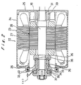
- a rotating assembly R as shown in FIG. 4. Specifically, simply by assembling relatively small parts on one side, most of the parts of the bearings are assembled into a cartridge structure which can be inserted into the stator in a socket-and-spigot joint (I) with the O-ring 40 interposed therebetween. Since the bearing parts form a cartridge structure, the axial end play (e) can easily be adjusted before they are inserted into the stator. Because the axial end play (e) can easily be adjusted, it may be greatly reduced or almost eliminated for preventing the bearings from being damaged due to shocks during shipment and also preventing foreign matter from finding its way to the sliding surfaces of the bearings.
- the O-ring 40 can absorb or eliminate errors in concentricity and perpendicularity of portions positioned at both side ends of the shaft 16 and supporting radial bearings and also dimensional errors of interfitting parts in the socket-and-spigot joint (I). Consequently, the parts in the socket-and-spigot joint (I) and the bearing housing 32 are not required to be highly dimensionally accurate.
- FIG. 5 shows a full-circumferential flow in-line pump having a canned motor which incorporates a bearing device according to another embodiment of the present invention.
- Those parts shown in FIG. 5 which are identical to those shown in FIG. 1 are denoted by identical reference characters, and will not be described in detail below.
- the bearing device on one side (left) is essentially similar as the bearing device on the one side (left) as shown in FIG. 1.
- the canned motor has a different bearing device on the other side.
- a bearing housing 52 is detachably joined to the side plate 25 in a socket-and-spigot joint with a resilient O-ring 53 being interposed between the bearing housing 52 and the side plate 25.
- the bearing housing 52 and the side plate 25 have grooves 52a, 25a defined respectively in radially outer and inner surfaces thereof which confront each other.
- the O-ring 53 is received in these grooves 52a, 25a.
- the bearing housing 52 is prevented from being axially dislodged from the side plate 25 by the O-ring 53.
- the bearing housing 52 holds the radial bearing 30 on its radially inner surface.
- the bearing housing 52 is also prevented from being axially detached from the side plate 52 by a collar 54 fixedly mounted on the shaft 16.
- the bearing housing 32 is prevented from being axially dislodged from the side plate 26 by a holder plate 41a fixed to the discharge-side casing 5.
- the bearing housings 32, 52 disposed respectively on the opposite end portions of the shaft 16 are floatingly supported by the respective side plates 25, 26. Therefore, errors in concentricity and perpendicularity of both sides bearing parts and also dimensional errors of interfitting parts in the socket-and-spigot joint can be eliminated more effectively than in the previous embodiment.
- the inner casing 10 comprises a partition 11a on the suction side and a guide device 12a.
- a cover plate 55 is mounted on the non-load-side end of the shaft 16 for preventing a slurry from entering the bearing device.
- the radial bearing 33 and the stationary thrust bearing 34 provide stationary thrust sliding surfaces.
- the stationary thrust bearing 34 may be dispensed with, and the radial bearing 33 may be axially extended such that an axial end surface thereof is held in sliding contact with the rotating thrust bearing 39.
- the holder plate 41 has a substantially conical guide surface 41a projecting toward a discharge port of the discharge-side pump casing 5 so as to guide fluid from the annular fluid passage 50 toward the discharge port of the discharge-side casing 5.
- the conical guide surface 41a has a plurality of slits 41s extending from a radially outward end to a radially inward end so that fluid is introduced into the canned motor 22.
- the slits 41s are radially formed on the conical guide surface 41a and have small slit width so as to serve as a filter.
- a fluid flows through the slits 41s into the canned motor 22, foreign matter in the fluid is removed by the slits 41s.
- the slits 41s are conical so as to be parallel to a direction of a fluid flow, foreign matter caught by the slits 41s is removed by being pushed in the dorection of fluid flow, thus preventing the slits 41s from being clogged. That is, the slit 41s has a self-cleaning function due to their shape.
- FIG. 5 a radial bearing device shown in FIG. 5, with a mechanism for preventing a radial bearing from rotating will be described in detail with reference to FIGS. 7(a) and 7(b) and 8.
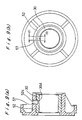
- the radial bearing 30 has an outer circumferential surface 30a on which a recess 30b is formed in a direction perpendicular to an axis of the radial bearing 30.
- the bearing housing 52 has an inner circumferential surface 52a on which a groove 52b is formed in parallel to an axis of the radial bearing 30.
- a key 56 made of resilient material such as rubber is interposed between the recess 30b and the groove 52b to prevent the radial bearing 30 from rotating.
- Side walls 30c, 30c positioned on both sides of the recess 30b are engaged with the key 56 to prevent the key 56 from being removed.
- impulse force applied to the radial bearing 30 at the time of starting rotation of the main shaft 16 can be absorbed by this resilient key 56 to thus protect the radial bearing 30 which is made of ceramics such as silicon carbide (SiC), which is weak against impulse force.
- SiC silicon carbide
- the key 56 is made of resilient material, dimensional accuracy of the radial bearing 30 is not required, and machining of the radial bearing 30 is not required after sintering.
- FIGS. 9(a) and 9(b) show a radial bearing device with a mechanism for preventing a radial bearing from rotating according to another embodiment of the present invention.
- the bearing housing 52 has a through hole 52c in a direction perpendicular to an axis thereof.
- the radial bearing 30 has a hole 30d, in a direction perpendicular to an axis thereof.
- the hole 30d does not pierce through the bearing body and is formed at the position corresponding to the through hole 52c.
- Resin 57 is injected in the through hole 52c and the hole 30d and solidified, whereby the radial bearing 30 is prevented from rotating with respect to the bearing housing 52.
- An inner diameter d 1 , of the through hole 52c is smaller than an inner diameter d 2 of the hole 30d, thus the resin 57 is prevented from being radially dislodged from the bearing housing 52.
- FIGS. 1 and 5 a thrust bearing device shown in FIGS. 1 and 5, with a mechanism for preventing a thrust bearing from rotating will be described in detail with reference to FIGS. 10 and 11.
- the stationary thrust bearing 34 and the rotating thrust bearing 39 are made of ceramics and in the form of thin plate.
- the thrust bearings 34, 39 have sliding surfaces 34a, 39a and backsides 34b, 39b, respectively.
- Recesses 34c, 39c are formed on the backsides 34b, 39b of the thrust bearings 34, 39, respectively.
- the bearing housing 32 and the thrust disk 37 have respective resilient pins 58, 59 horizontally provided thereon.
- the pin 58 is engaged with the recess 34c to prevent the thrust bearing 34 from rotating, and the pin 59 is engaged with the recess 39c to rotate the thrust bearing 39 together with the thrust disk 37.
- the recesses 34c, 39c may be formed on inner circumferential edges of the thrust bearings 34, 39 as shown by broken line in FIG. 11(b).
- the pins 58, 59 engage the recesses 34c, 39c, respectively, impulse force applied to the thrust bearings 34, 39 at the time of starting rotation of the main shaft 16 can be absorbed by the resiliency of the pins to thus protect the ceramic thrust bearings 34, 39 which are weak against impulse forces.
- pins 58, 59 are made of resilient material, dimensional accuracy of the thrust bearings 34, 39 is not required, and machining of the thrust bearings 34, 39 is not required after sintering.
Landscapes
- Engineering & Computer Science (AREA)
- General Engineering & Computer Science (AREA)
- Mechanical Engineering (AREA)
- Chemical & Material Sciences (AREA)
- Ceramic Engineering (AREA)
- Power Engineering (AREA)
- Physics & Mathematics (AREA)
- Fluid Mechanics (AREA)
- Motor Or Generator Frames (AREA)
- Structures Of Non-Positive Displacement Pumps (AREA)
- Support Of The Bearing (AREA)
Claims (16)
- Lagervorrichtung der Patronenbauart in einem gekapselten Motor (22) mit einem Motorrahmen (23) und einem bezüglich des Motorrahmens drehbaren Rotor (28) der eine Welle (16) aufweist, wobei die Lagervorrichtung der Patronenbauart in der Lage ist bidirektionale Schubkräfte aufzunehmen wobei folgendes vorgesehen ist:ein lösbar am Motorrahmen (23) angebrachtes Lagergehäuse (32);ein durch das Lagergehäuse (32) getragenes Radiallager (33), wobei die Welle (16) drehbar durch das Radiallager (33) gelagert ist;ein Paar von axial beabstandeten stationären Schubgleitoberflächen auf dem Lagergehäuse (32);ein Paar von axial beabstandeten sich drehenden Schubgleitoberflächen auf dem Rotor in gegenüberliegender Beziehung mit den jeweiligen stationären Schubgleitoberflächen; undein elastisches Glied (40) angeordnet zwischen dem Motorrahmen (23) und dem Lagergehäuse (32) zum elastischen Halten des Lagergehäuses in radial Position bezüglich des Motorrahmens.
- Lagervorrichtung nach Anspruch 1 wobei eine der stationären Schubgleitoberflächen auf einem Schublager (34) getragen durch das Lagergehäuse (32) geformt ist.
- Lagervorrichtung nach Anspruch 2 wobei ferner ein elastischer Stift (58) zwischen dem Lagergehäuse (32) und dem Schublager (34) derart angeordnet ist, daß das Schublager an einer Drehung bezüglich des erwähnten Lagergehäuses gehindert ist.
- Lagervorrichtung nach einem oder mehreren der vorherigen Ansprüche wobei eine der sich drehenden Schubgleitoberflächen auf einem Schublager (39) geformt ist und zwar getragen durch eine Schubscheibe (37) befestigt an der Welle (16).
- Lagervorrichtung nach Anspruch 4 wobei ferner ein elastischer Stift (59) zwischen der Schubscheibe (37) und dem Schublager (39) derart angeordnet ist, daß das Schublager daran gehindert wird sich bezüglich der Schubscheibe zu drehen.
- Lagervorrichtung nach einem der vorherigen Ansprüche wobei ferner folgendes vorgesehen ist:ein zweites Lagergehäuse (52) angebracht am Motorrahmen (23);ein zweites Radiallager (30) aus Keramik und getragen durch das zweite Lagergehäuse (52), wobei die Welle (16) drehbar durch das zweite Radiallager (30) getragen wird und zwar an einer Stelle beabstandet gegenüber dem Radiallager (33);eine Ausnehmung (30b) gebildet in einer Außenumfangsoberfläche (30a) des zweiten Radiallagers (30);ein Nut (52b) gebildet in einer Innenoberfläche des zweiten Lagergehäuses (52) und sich axial zu dem zweiten Lagergehäuse erstreckend, wobei die Nut (52b) ein offenes Ende aufweist; undein elastisches Eingriffselement (56) zwischen der Ausnehmung (30b) und der Nut (52b) zur Verhinderung das sich das zweite Radiallager bezüglich des zweiten Lagergehäuses dreht.
- Lagervorrichtung nach einem der Ansprüche 1 bis 5 wobei ferner folgendes vorgesehen ist:ein zweites Lagergehäuse (52) angebracht am Motorrahmen;ein zweites Radiallager (30) aus Keramik und getragen durch das Lagergehäuse, wobei die Welle drehbar durch das zweite Radiallager (30) getragen wird und zwar an einer Stelle beabstandet von dem Radiallager (33);ein hindurchgehendes Loch (52c) gebildet in dem zweiten Lagergehäuse (52);eine Ausnehmung (30d) gebildet auf dem zweiten Radiallager (30) an einer Position entsprechend dem hindurchgehenden Loch; undin das hindurchgehenden Loch (52c) und die Ausnehmung (30d) eingespritztes Harz (57) welches darinnen verfestigt ist.
- Lagervorrichtung nach einem oder mehreren der vorhergehenden Ansprüche wobei das Lagergehäuse (32; 52) einen Außendurchmesser besitzt, der größer ist als ein Innendurchmesser einer zylindrischen Einkapselung des gekapselten Motors (22) angebracht in dem Motorrahmen.
- Lagervorrichtung nach einem oder mehrere der vorhergehenden Ansprüche wobei das elastische Glied (40) ein O'Ring ist bzw. diesen aufweist.
- Lagervorrichtung nach einem oder mehreren der vorhergehenden Ansprüche wobei die Haltemittel eine Halteplatte (41) vorgesehen an dem Motorrahmen (23) aufweisen.
- Lagervorrichtung nach einem der Ansprüche 1 bis 5 wobei ferner folgendes vorgesehen ist:ein zweites Lagergehäuse (52) lösbar angebracht am Motorrahmen (23);ein zweites Radiallager (30) getragen durch das zweite Lagergehäuse (52) wobei die Welle (16) drehbar durch das zweite Radiallager (30) getragen ist; undein zweites elastisches Glied (53) angeordnet zwischen dem Motorrahmen (23) und dem zweiten Lagergehäuse (52) um das zweite Lagergehäuse in Radialposition bezüglich des Motorrahmens zu halten.
- Lagervorrichtung nach Anspruch 11 wobei ferner Haltemittel (53; 54) vorgesehen sind, um das Lagergehäuse in Position gegenüber einer Entfernung in eine Axialrichtung des Motors zu halten.
- Lagervorrichtung nach Anspruch 12 wobei die Haltemittel ein O'Ring (53) aufweisen, der in einer Nut (52a) vorgesehen ist, die am Lagergehäuse (52) gebildet ist und, wobei ein Nut (25a) am Motorrahmen gebildet ist.
- Lagervorrichtung nach Anspruch 11 wobei das zweite elastische Glied einen O'Ring aufweist bzw. ein O'Ring ist.
- Lagervorrichtung nach Anspruch 12 wobei die Haltemittel einen Kragen (54) aufweisen und zwar vorgesehen auf der Welle (16) zum Halten des zweiten Lagergehäuses (52) in Position gegen Entfernung in Axialrichtung des Rotors (28).
- Lagervorrichtung nach einem oder mehreren der vorhergehenden Ansprüche wobei der gekapselte Motor für eine "in-Line"-Pumpe mit voller Umfangsströmung vorgesehen ist.
Applications Claiming Priority (10)
| Application Number | Priority Date | Filing Date | Title |
|---|---|---|---|
| JP120182/92 | 1992-04-14 | ||
| JP12018392A JPH05302588A (ja) | 1992-04-14 | 1992-04-14 | インラインポンプ |
| JP120183/92 | 1992-04-14 | ||
| JP12018292 | 1992-04-14 | ||
| JP171691/92 | 1992-06-05 | ||
| JP171689/92 | 1992-06-05 | ||
| JP171684/92 | 1992-06-05 | ||
| JP17169192A JP2847335B2 (ja) | 1992-06-05 | 1992-06-05 | ラジアル軸受装置及び該ラジアル軸受装置を備えたキャンドモータ |
| JP17168992A JP2968643B2 (ja) | 1992-06-05 | 1992-06-05 | スラスト軸受装置及び該スラスト軸受装置を備えたキャンドモータ |
| JP17168492A JPH05340428A (ja) | 1992-06-05 | 1992-06-05 | ラジアル軸受装置及び該ラジアル軸受装置を備えたキャンドモータ |
Publications (3)
| Publication Number | Publication Date |
|---|---|
| EP0566088A2 EP0566088A2 (de) | 1993-10-20 |
| EP0566088A3 EP0566088A3 (de) | 1994-10-26 |
| EP0566088B1 true EP0566088B1 (de) | 1997-07-09 |
Family
ID=27526868
Family Applications (1)
| Application Number | Title | Priority Date | Filing Date |
|---|---|---|---|
| EP93106066A Expired - Lifetime EP0566088B1 (de) | 1992-04-14 | 1993-04-14 | Lageranordnung zur Verwendung in einem Spaltrohrmotor |
Country Status (6)
| Country | Link |
|---|---|
| US (1) | US5385454A (de) |
| EP (1) | EP0566088B1 (de) |
| KR (1) | KR100303616B1 (de) |
| AT (1) | ATE155294T1 (de) |
| DE (1) | DE69311948T2 (de) |
| ES (1) | ES2104991T3 (de) |
Families Citing this family (19)
| Publication number | Priority date | Publication date | Assignee | Title |
|---|---|---|---|---|
| JP2958218B2 (ja) * | 1993-07-16 | 1999-10-06 | 株式会社荏原製作所 | ポンプ |
| AU682393B2 (en) * | 1993-10-13 | 1997-10-02 | Ebara Corporation | Motor stator assembly and full-circumferential flow pump employing such motor stator assembly |
| JP3035883B2 (ja) * | 1994-12-27 | 2000-04-24 | 株式会社荏原製作所 | 軸受装置及び該軸受装置を備えたポンプ |
| JPH08232884A (ja) * | 1995-02-24 | 1996-09-10 | Ebara Corp | 全周流型ポンプ群及びその製造方法 |
| DE19529476C2 (de) * | 1995-08-11 | 2000-08-10 | Deutsch Zentr Luft & Raumfahrt | Flügel mit schubsteifen Flügelschalen aus Faserverbundwerkstoffen für Luftfahrzeuge |
| US5911685A (en) * | 1996-04-03 | 1999-06-15 | Guidant Corporation | Method and apparatus for cardiac blood flow assistance |
| DE19613564C1 (de) | 1996-04-04 | 1998-01-08 | Guenter Prof Dr Rau | Intravasale Blutpumpe |
| US5964694A (en) * | 1997-04-02 | 1999-10-12 | Guidant Corporation | Method and apparatus for cardiac blood flow assistance |
| US6176822B1 (en) | 1998-03-31 | 2001-01-23 | Impella Cardiotechnik Gmbh | Intracardiac blood pump |
| US6759774B1 (en) * | 2001-03-08 | 2004-07-06 | Lawrence Pumps, Inc | Low speed canned motor |
| JP2006147402A (ja) * | 2004-11-22 | 2006-06-08 | Alps Electric Co Ltd | 回転操作型電気部品 |
| DE102006029399A1 (de) * | 2006-06-27 | 2007-03-01 | Cincinnati Extrusion Gmbh | Elektromotor mit Axiallager |
| WO2011022557A2 (en) * | 2009-08-19 | 2011-02-24 | Aspen Motion Technologies, Inc. D/B/A | Magnetic drive pump assembly with integrated motor |
| DE102009060549A1 (de) * | 2009-12-23 | 2011-06-30 | Wilo Se, 44263 | EC-Motorkreiselpumpe |
| US8593024B2 (en) | 2010-04-12 | 2013-11-26 | Hamilton Sundstrand Space Systems International, Inc. | Implementation of a non-metallic barrier in an electric motor |
| DE102012008015A1 (de) * | 2012-04-24 | 2013-10-24 | Daimler Ag | Rotorträger und Verfahren zur Herstellung eines Rotorträgers |
| US9144638B2 (en) | 2013-03-14 | 2015-09-29 | Thoratec Corporation | Blood pump rotor bearings |
| KR102171452B1 (ko) | 2019-06-21 | 2020-10-29 | 엘지전자 주식회사 | 모터 어셈블리 및 그 제조 방법 |
| CN121152924A (zh) * | 2024-04-15 | 2025-12-16 | 广东德昌电机有限公司 | 流体泵 |
Family Cites Families (32)
| Publication number | Priority date | Publication date | Assignee | Title |
|---|---|---|---|---|
| US2030193A (en) * | 1932-11-02 | 1936-02-11 | Gilbert Co A C | Bearing structure |
| US2080683A (en) * | 1934-11-22 | 1937-05-18 | Fairbanks Morse & Co | Pump construction |
| US2406947A (en) * | 1944-08-30 | 1946-09-03 | Smith Corp A O | Centrifugal pump |
| US2875694A (en) * | 1954-09-08 | 1959-03-03 | Fostoria Pressed Steel Corp | Motor driven pumps |
| GB765263A (en) * | 1955-02-21 | 1957-01-09 | Chempump Corp | Improvements in motor driven pumps |
| US2993131A (en) * | 1955-03-28 | 1961-07-18 | Dictaphone Corp | Small electric motor |
| US2868133A (en) * | 1956-09-14 | 1959-01-13 | Jane Barr Clark | Centrifugal pumps |
| GB858975A (en) * | 1958-05-21 | 1961-01-18 | Rhodes Brydon & Youatt Ltd | Improvements in motor driven centrifugal pumps |
| US3138105A (en) * | 1961-02-08 | 1964-06-23 | Fostoria Corp | Motor driven pumps |
| NL125603C (de) * | 1964-03-02 | |||
| US3220350A (en) * | 1964-09-03 | 1965-11-30 | Crane Co | Motor driven pump |
| CH563530A5 (de) * | 1973-03-22 | 1975-06-30 | Bbc Sulzer Turbomaschinen | |
| DE2340303A1 (de) * | 1973-08-09 | 1975-02-20 | Bosch Gmbh Robert | Lageranordnung fuer elektromotoren |
| US3885767A (en) * | 1974-01-23 | 1975-05-27 | Edward J Olowinski | Snap-in mounting and mounting assembly |
| US3918852A (en) * | 1974-06-24 | 1975-11-11 | James Coolidge Carter | Pump |
| GB2087632B (en) * | 1977-11-01 | 1982-12-15 | Atomic Energy Authority Uk | Carbonaceous deposition reduction |
| US4234293A (en) * | 1979-03-27 | 1980-11-18 | Dresser Industries, Inc. | Axial balancing system for motor driven pumps |
| US4427337A (en) * | 1981-02-17 | 1984-01-24 | The United States Of America As Represented By The United States Department Of Energy | Bearing for liquid metal pump |
| US4363608A (en) * | 1981-04-20 | 1982-12-14 | Borg-Warner Corporation | Thrust bearing arrangement |
| AU8314182A (en) * | 1981-11-25 | 1983-06-02 | Marley-Wylain Co., The | Submersible motor |
| JPS58192997A (ja) * | 1982-05-07 | 1983-11-10 | Hitachi Ltd | 立形モ−タポンプ |
| DE3520560A1 (de) * | 1985-06-07 | 1986-12-11 | Klein Schanzlin & Becker Ag | Keramikgleitlager fuer pumpenwellenlager |
| DE3715216A1 (de) * | 1987-05-07 | 1988-11-17 | Doll Robert | Tauchpumpe, insbesondere fuer tiefsiedende fluessigkeiten |
| US5009578A (en) * | 1987-10-27 | 1991-04-23 | Crane Co. | Motor driven pumps |
| FR2624923B1 (fr) * | 1987-12-22 | 1990-05-18 | Bellmann Michel | Ventilateur axial ou centrifuge-axial pour la circulation d'un gaz |
| US4880362A (en) * | 1988-05-24 | 1989-11-14 | Laing Karsten A | Rotor with stabilizing magnets |
| US4904166A (en) * | 1988-11-30 | 1990-02-27 | White Consolidated Industries, Inc. | Vertical axis motor-pump assembly for clothes washing machine |
| EP0431332B1 (de) * | 1989-11-08 | 1995-11-02 | Sanwa Tokushu Seiko Co., Ltd. | Magnetisch angetriebene Pumpe |
| US5232342A (en) * | 1990-07-07 | 1993-08-03 | David Brown Engineering Limited | High pressure multi-stage centrifugal pumps |
| US5056939A (en) * | 1990-07-12 | 1991-10-15 | Ingersoll-Rand Company | Journal bearing retainer system |
| US5129795A (en) * | 1991-05-31 | 1992-07-14 | Powerdyne Corporation | Motor driven pump |
| US5207512A (en) * | 1992-05-06 | 1993-05-04 | Dresser-Rand Company | Spherical roller bearing assembly |
-
1993
- 1993-04-14 DE DE69311948T patent/DE69311948T2/de not_active Expired - Fee Related
- 1993-04-14 KR KR1019930006195A patent/KR100303616B1/ko not_active Expired - Fee Related
- 1993-04-14 AT AT93106066T patent/ATE155294T1/de active
- 1993-04-14 US US08/045,694 patent/US5385454A/en not_active Expired - Fee Related
- 1993-04-14 ES ES93106066T patent/ES2104991T3/es not_active Expired - Lifetime
- 1993-04-14 EP EP93106066A patent/EP0566088B1/de not_active Expired - Lifetime
Also Published As
| Publication number | Publication date |
|---|---|
| ATE155294T1 (de) | 1997-07-15 |
| EP0566088A3 (de) | 1994-10-26 |
| EP0566088A2 (de) | 1993-10-20 |
| US5385454A (en) | 1995-01-31 |
| KR100303616B1 (ko) | 2001-11-30 |
| DE69311948T2 (de) | 1998-02-19 |
| KR930022674A (ko) | 1993-11-24 |
| DE69311948D1 (de) | 1997-08-14 |
| ES2104991T3 (es) | 1997-10-16 |
Similar Documents
| Publication | Publication Date | Title |
|---|---|---|
| US5385454A (en) | Bearing device for use in a canned motor | |
| EP0631366B1 (de) | Magnetisch angetriebene Pumpe mit hinten angeordnetem Drucklagerelement | |
| US4934836A (en) | Dynamic pressure type fluid bearing device | |
| US5501582A (en) | Magnetically driven centrifugal pump | |
| US10253783B2 (en) | Pump arrangement comprising a plain bearing arrangement | |
| US7237736B1 (en) | Grinder pump with self aligning cutter assembly | |
| US6726215B2 (en) | Dynamic pressure seal device and rotary joint device using the same | |
| KR101097654B1 (ko) | 방사형 회전식 운송 어셈블리 | |
| US3499388A (en) | Centrifugal pump | |
| US3433164A (en) | Motor-pump unit | |
| US4478550A (en) | Pump apparatus | |
| WO2002099283A1 (en) | Magnet pump | |
| CN111365284B (zh) | 轴承承载部件、压缩机和冷媒循环系统 | |
| US4492515A (en) | Pump apparatus | |
| US4131386A (en) | Sealing system for centrifugal pump | |
| US4253809A (en) | Vane compressor with rotor having metallic base and vane slots and a periphery of lower specific gravity | |
| JP4972984B2 (ja) | 両吸込渦巻ポンプおよびその羽根車並びに羽根車の製造方法 | |
| US5927941A (en) | High-temperature motor pump | |
| JP2878926B2 (ja) | キャンドモータの軸受装置及び該軸受装置を備えたキャンドモータ | |
| JP2847335B2 (ja) | ラジアル軸受装置及び該ラジアル軸受装置を備えたキャンドモータ | |
| JPH0239638B2 (de) | ||
| US4875826A (en) | Pitot pump assembly for a rotating fluid management device | |
| JP2020139433A (ja) | 回転機械 | |
| EP0781924A2 (de) | Hydraulische Flügelzellenmaschine | |
| TW202603276A (zh) | 馬達泵浦 |
Legal Events
| Date | Code | Title | Description |
|---|---|---|---|
| PUAI | Public reference made under article 153(3) epc to a published international application that has entered the european phase |
Free format text: ORIGINAL CODE: 0009012 |
|
| AK | Designated contracting states |
Kind code of ref document: A2 Designated state(s): AT BE CH DE DK ES FR GB GR IE IT LI LU MC NL PT SE |
|
| PUAL | Search report despatched |
Free format text: ORIGINAL CODE: 0009013 |
|
| AK | Designated contracting states |
Kind code of ref document: A3 Designated state(s): AT BE CH DE DK ES FR GB GR IE IT LI LU MC NL PT SE |
|
| 17P | Request for examination filed |
Effective date: 19950331 |
|
| 17Q | First examination report despatched |
Effective date: 19950712 |
|
| GRAG | Despatch of communication of intention to grant |
Free format text: ORIGINAL CODE: EPIDOS AGRA |
|
| GRAH | Despatch of communication of intention to grant a patent |
Free format text: ORIGINAL CODE: EPIDOS IGRA |
|
| GRAH | Despatch of communication of intention to grant a patent |
Free format text: ORIGINAL CODE: EPIDOS IGRA |
|
| GRAA | (expected) grant |
Free format text: ORIGINAL CODE: 0009210 |
|
| AK | Designated contracting states |
Kind code of ref document: B1 Designated state(s): AT BE CH DE DK ES FR GB GR IE IT LI LU MC NL PT SE |
|
| PG25 | Lapsed in a contracting state [announced via postgrant information from national office to epo] |
Ref country code: NL Free format text: LAPSE BECAUSE OF FAILURE TO SUBMIT A TRANSLATION OF THE DESCRIPTION OR TO PAY THE FEE WITHIN THE PRESCRIBED TIME-LIMIT Effective date: 19970709 Ref country code: LI Free format text: LAPSE BECAUSE OF FAILURE TO SUBMIT A TRANSLATION OF THE DESCRIPTION OR TO PAY THE FEE WITHIN THE PRESCRIBED TIME-LIMIT Effective date: 19970709 Ref country code: GR Free format text: LAPSE BECAUSE OF FAILURE TO SUBMIT A TRANSLATION OF THE DESCRIPTION OR TO PAY THE FEE WITHIN THE PRESCRIBED TIME-LIMIT Effective date: 19970709 Ref country code: DK Effective date: 19970709 Ref country code: CH Free format text: LAPSE BECAUSE OF FAILURE TO SUBMIT A TRANSLATION OF THE DESCRIPTION OR TO PAY THE FEE WITHIN THE PRESCRIBED TIME-LIMIT Effective date: 19970709 Ref country code: BE Effective date: 19970709 Ref country code: AT Effective date: 19970709 |
|
| REF | Corresponds to: |
Ref document number: 155294 Country of ref document: AT Date of ref document: 19970715 Kind code of ref document: T |
|
| REG | Reference to a national code |
Ref country code: CH Ref legal event code: EP |
|
| REF | Corresponds to: |
Ref document number: 69311948 Country of ref document: DE Date of ref document: 19970814 |
|
| ITF | It: translation for a ep patent filed | ||
| PG25 | Lapsed in a contracting state [announced via postgrant information from national office to epo] |
Ref country code: SE Effective date: 19971009 |
|
| REG | Reference to a national code |
Ref country code: ES Ref legal event code: FG2A Ref document number: 2104991 Country of ref document: ES Kind code of ref document: T3 |
|
| PG25 | Lapsed in a contracting state [announced via postgrant information from national office to epo] |
Ref country code: PT Effective date: 19971017 |
|
| ET | Fr: translation filed | ||
| NLV1 | Nl: lapsed or annulled due to failure to fulfill the requirements of art. 29p and 29m of the patents act | ||
| REG | Reference to a national code |
Ref country code: CH Ref legal event code: PL |
|
| PG25 | Lapsed in a contracting state [announced via postgrant information from national office to epo] |
Ref country code: LU Free format text: LAPSE BECAUSE OF NON-PAYMENT OF DUE FEES Effective date: 19980414 Ref country code: IE Free format text: LAPSE BECAUSE OF NON-PAYMENT OF DUE FEES Effective date: 19980414 |
|
| PLBE | No opposition filed within time limit |
Free format text: ORIGINAL CODE: 0009261 |
|
| 26N | No opposition filed | ||
| PG25 | Lapsed in a contracting state [announced via postgrant information from national office to epo] |
Ref country code: MC Free format text: LAPSE BECAUSE OF NON-PAYMENT OF DUE FEES Effective date: 19981031 |
|
| REG | Reference to a national code |
Ref country code: GB Ref legal event code: IF02 |
|
| PGFP | Annual fee paid to national office [announced via postgrant information from national office to epo] |
Ref country code: FR Payment date: 20020326 Year of fee payment: 10 |
|
| PGFP | Annual fee paid to national office [announced via postgrant information from national office to epo] |
Ref country code: GB Payment date: 20020327 Year of fee payment: 10 |
|
| PGFP | Annual fee paid to national office [announced via postgrant information from national office to epo] |
Ref country code: ES Payment date: 20020416 Year of fee payment: 10 |
|
| PGFP | Annual fee paid to national office [announced via postgrant information from national office to epo] |
Ref country code: DE Payment date: 20020430 Year of fee payment: 10 |
|
| PG25 | Lapsed in a contracting state [announced via postgrant information from national office to epo] |
Ref country code: GB Free format text: LAPSE BECAUSE OF NON-PAYMENT OF DUE FEES Effective date: 20030414 |
|
| PG25 | Lapsed in a contracting state [announced via postgrant information from national office to epo] |
Ref country code: ES Free format text: LAPSE BECAUSE OF NON-PAYMENT OF DUE FEES Effective date: 20030415 |
|
| PG25 | Lapsed in a contracting state [announced via postgrant information from national office to epo] |
Ref country code: DE Free format text: LAPSE BECAUSE OF NON-PAYMENT OF DUE FEES Effective date: 20031101 |
|
| GBPC | Gb: european patent ceased through non-payment of renewal fee |
Effective date: 20030414 |
|
| PG25 | Lapsed in a contracting state [announced via postgrant information from national office to epo] |
Ref country code: FR Free format text: LAPSE BECAUSE OF NON-PAYMENT OF DUE FEES Effective date: 20031231 |
|
| REG | Reference to a national code |
Ref country code: FR Ref legal event code: ST |
|
| REG | Reference to a national code |
Ref country code: ES Ref legal event code: FD2A Effective date: 20030415 |
|
| PG25 | Lapsed in a contracting state [announced via postgrant information from national office to epo] |
Ref country code: IT Free format text: LAPSE BECAUSE OF NON-PAYMENT OF DUE FEES;WARNING: LAPSES OF ITALIAN PATENTS WITH EFFECTIVE DATE BEFORE 2007 MAY HAVE OCCURRED AT ANY TIME BEFORE 2007. THE CORRECT EFFECTIVE DATE MAY BE DIFFERENT FROM THE ONE RECORDED. Effective date: 20050414 |