EP0566211A1 - Dispositif de ventilation silencieux avec un boîtier allongé et conduit de ventilation en forme de fente - Google Patents
Dispositif de ventilation silencieux avec un boîtier allongé et conduit de ventilation en forme de fente Download PDFInfo
- Publication number
- EP0566211A1 EP0566211A1 EP93201102A EP93201102A EP0566211A1 EP 0566211 A1 EP0566211 A1 EP 0566211A1 EP 93201102 A EP93201102 A EP 93201102A EP 93201102 A EP93201102 A EP 93201102A EP 0566211 A1 EP0566211 A1 EP 0566211A1
- Authority
- EP
- European Patent Office
- Prior art keywords
- ventilating
- mouth
- channel
- ventilating channel
- wall
- Prior art date
- Legal status (The legal status is an assumption and is not a legal conclusion. Google has not performed a legal analysis and makes no representation as to the accuracy of the status listed.)
- Granted
Links
- 238000013016 damping Methods 0.000 title claims abstract description 36
- 239000000463 material Substances 0.000 claims abstract description 21
- 239000002982 water resistant material Substances 0.000 claims abstract description 4
- 239000002184 metal Substances 0.000 claims description 4
- XLYOFNOQVPJJNP-UHFFFAOYSA-N water Substances O XLYOFNOQVPJJNP-UHFFFAOYSA-N 0.000 description 7
- 241000238631 Hexapoda Species 0.000 description 3
- 238000010276 construction Methods 0.000 description 2
- 238000004519 manufacturing process Methods 0.000 description 2
- 230000000149 penetrating effect Effects 0.000 description 2
- 230000002411 adverse Effects 0.000 description 1
- 230000000694 effects Effects 0.000 description 1
- 238000002474 experimental method Methods 0.000 description 1
- 238000009413 insulation Methods 0.000 description 1
- 238000000034 method Methods 0.000 description 1
- 238000012986 modification Methods 0.000 description 1
- 230000004048 modification Effects 0.000 description 1
- 238000005192 partition Methods 0.000 description 1
- 230000035515 penetration Effects 0.000 description 1
- 230000000717 retained effect Effects 0.000 description 1
- 238000009423 ventilation Methods 0.000 description 1
Images

Classifications
-
- F—MECHANICAL ENGINEERING; LIGHTING; HEATING; WEAPONS; BLASTING
- F24—HEATING; RANGES; VENTILATING
- F24F—AIR-CONDITIONING; AIR-HUMIDIFICATION; VENTILATION; USE OF AIR CURRENTS FOR SCREENING
- F24F7/00—Ventilation
-
- E—FIXED CONSTRUCTIONS
- E06—DOORS, WINDOWS, SHUTTERS, OR ROLLER BLINDS IN GENERAL; LADDERS
- E06B—FIXED OR MOVABLE CLOSURES FOR OPENINGS IN BUILDINGS, VEHICLES, FENCES OR LIKE ENCLOSURES IN GENERAL, e.g. DOORS, WINDOWS, BLINDS, GATES
- E06B7/00—Special arrangements or measures in connection with doors or windows
- E06B7/02—Special arrangements or measures in connection with doors or windows for providing ventilation, e.g. through double windows; Arrangement of ventilation roses
-
- F—MECHANICAL ENGINEERING; LIGHTING; HEATING; WEAPONS; BLASTING
- F24—HEATING; RANGES; VENTILATING
- F24F—AIR-CONDITIONING; AIR-HUMIDIFICATION; VENTILATION; USE OF AIR CURRENTS FOR SCREENING
- F24F13/00—Details common to, or for air-conditioning, air-humidification, ventilation or use of air currents for screening
- F24F13/24—Means for preventing or suppressing noise
-
- F—MECHANICAL ENGINEERING; LIGHTING; HEATING; WEAPONS; BLASTING
- F24—HEATING; RANGES; VENTILATING
- F24F—AIR-CONDITIONING; AIR-HUMIDIFICATION; VENTILATION; USE OF AIR CURRENTS FOR SCREENING
- F24F7/00—Ventilation
- F24F2007/0025—Ventilation using vent ports in a wall
Definitions
- This invention relates to a sound-damping ventilating device comprising a block-shaped housing which is substantially elongated in the direction of its width and has a slotted ventilating channel terminating at both ends in a mouth forming a gap in a housing wall, this ventilating channel and these mouths extending substantially throughout the width of the housing, the slot walls of the ventilating channel being partly bounded by sound-damping material and, at least in the vicinity of one mouth, by a wall of water-resistant material, whilst the other mouth is covered by a valve element with closable planar apertures.
- the ventilating channel as viewed in cross-section, has an L-shaped configuration, one leg of the L-shape extending substantially horizontally and the other extending substantially vertically through the elongated, block-shaped housing.
- the other mouth is located in line with the free end of the horizontal part of the ventilating channel, whilst the one mouth is located at the free end of the vertical part of the ventilating channel.
- the object of the present invention is to improve a ventilating device of the above-described type, while maintaining the sound-damping and watertightness properties, such that the air resistance in the ventilating channel is reduced.
- the ventilating channel at least over a part of its length between the two mouths and starting from one mouth in the direction of the other mouth, extends slantingly upwards in the substantially elongated, block-shaped housing and the planar apertures extend substantially perpendicularly to the direction of passage of the ventilating channel in the area adjacent to the valve element.
- the portion of the ventilating channel that extends slantingly from the one mouth includes an angle of the order of 40° with a horizontal plane or a part of the sound-damping ventilating device to be arranged horizontally.
- valve element can always be a standard part.
- the part of the housing comprising the portion of the ventilating channel that slants upwards from one mouth. If possible, this should be standard as well.
- the less slanting portion of the ventilating channel includes an angle of the order of 35° with the portion of the ventilating channel that extends slantingly from the one mouth. It may be observed that a bent channel has a greater resistance than a straight channel. In the present case, however, by opting for the slight bend and a slightly higher air resistance, an optimum is achieved as regards costs, operations, sound-damping and ventilation for the entire range of sound-damping devices of the present type.
- a ventilating device of a slightly larger passage will have to be chosen than would have been the case if a straight ventilating channel had been opted for; the attendant additional costs, however, are amply outweighed by the advantages obtained by the standardization as a result of the choice of the slight bend in the ventilating channel.
- openings have been formed in the ventilating channel by assembling the ventilating device from:
- both the height and the length of the ventilating channel are stepwise variable, whilst, by an appropriate choice of the angle included by the ends of the lower walls starting from the one mouth and the other mouth, located in the same plane, a lower wall starting from the other mouth matches each stepwise extended intermediate part and unchanged first part, this lower wall being identical to a lower wall starting from the other mouth, that matches a ventilating channel with a height smaller by one step and a length of the intermediate part shorter by one step.
- a low air resistance has been obtained inter alia by arranging the valve element perpendicularly to the slanting ventilating channel.
- the ventilating channel, adjacent the other mouth widens flaringly to the height of the apertures in the valve element.
- the space within the housing that is not occupied by the ventilating channel is filled up with sound-damping material.
- a continuous wall will have to be present throughout the height over which rain water may be driven up into the ventilating channel. In that area, the sound-damping material cannot form the wall of the ventilating channel.
- the portion of the ventilating channel that extends slantingly from the one mouth is bounded by continuous walls of a relatively stiff material, such as a metal
- the less slanting portion is bounded by walls of a relatively stiff material, such as a metal, provided with openings, typically forming a continuous gap in the relatively stiff wall of that channel in a direction transverse to the ventilating channel, so that the channel wall is formed by sound-damping material.
- the part of the housing that comprises the part of the ventilating channel that extends slantingly from the one mouth as well as the part of the less slanting portion as far as the opening may be standardized.
- the openings in the less slanting portion of the ventilating channel may be located opposite each other, which may adversely affect the sound-damping effect.
- the portion of the ventilating channel that extends slantingly from the one mouth remains straight, whilst, by virtue of the projecting wall portion, there is a lesser chance that rain drops, falling at a slant, will end up on the lower wall bounding the ventilating channel, so that the amount of water that may be driven up is appreciably reduced.
- Fig. 1 shows a sound-damping ventilating device, the housing of which is composed of a plurality of elongate sections 1-4. It is already noted here that these sections may each be composed of a plurality of separate parts and that the sections are shown in an extremely schematic and elementary form. Shown equally schematically in block-shape are a thermally insulating connection 5 between the sections 1 and 3 and a thermally insulating connection 6 between the sections 2 and 4. At the longitudinal ends, the sections are coupled by means of end partitions, one being indicated by reference numeral 7.
- a ventilating channel 8 with a mouth 9 Formed between the sections 1 and 2 is a ventilating channel 8 with a mouth 9, to which end section 2 comprises a section part 2a, which includes an angle of the order of 40° with a section part 2b to be arranged horizontally, and merges into a section part 2c, which includes an angle of the order of 35° with the section part 2a, whilst the section 1 comprises a section part 1a and an adjoining section part 1b, extending parallel to section parts 2a and 2c, respectively. Extending in line with the section part 1a is a section part 1c, which serves as a shield against rain for the ventilating channel 8.
- section part 3a Extending in line with section part 1b is a section part 3a and extending in line with section part 2c is a section part 4a, the section parts 3a and 4a forming a continuation and at the same time the other end of the ventilating channel 8 terminating in a mouth 10.
- the mouth 10 Via slanting section parts 3b and 4b, the mouth 10 has been widened to the height of the housing formed by the sections 1-4, the mouth being covered by a valve element 11, which is arranged substantially perpendicularly to the direction of the ventilating channel as defined by the section parts 1b, 2c, 3a and 4a and comprises closable apertures.
- valve element of the plate-shaped type typically use is made of a valve element of the plate-shaped type, with a plurality of apertured plates arranged so as to be movable over and along each other, such that the apertures in the plates can be brought into alignment with each other or the apertures in one plate are covered by portions of the plate between the apertures in the other plate.
- the valve element In the former condition of the plates, the valve element is in the fully opened position; in the latter condition of the plates, the valve element is in the closed position, whilst any position between the open and the closed position can be set in stepless manner by moving the plates relative to each other to a corresponding degree.
- an insect screen is arranged behind the apertures in the valve element 11.
- a space 12 which is filled with a sound-damping material, forming the wall of the ventilating channel 8 between the free ends of the section parts 1b and 3a.
- the sections 2 and 4 define a space 13 which is likewise filled with sound-damping material, again forming the wall of the ventilating channel 8 between the free ends of the section parts 2c and 4a.
- the spaces 12 and 13 at the same time function as resonator compartments, with the wall portions of the ventilating channel 8 consisting of sound-damping material forming the access openings to those resonator compartments. From a sound-damping point of view, it is less advantageous if the entrances of two resonator compartments are located opposite each other. Should it be important for the present sound-damping ventilating device that the resonator compartments operate as effectively as possible, then a plate-shaped member 14 of an acoustically hard material, indicated by broken lines, may be arranged in the ventilating channel 8 between the two openings so as to shield the two openings relatively to each other.
- section part 3a' and 4a' are equal to that of the section part 3a and 4a, respectively, and the angle included by the section parts 3a' and 3b' is equal to the angle included by the section parts 3a and 3b, which also applies to the angle included by the section parts 4a', 4b' and 4a, 4b, respectively; only the lengths of 3b' and 4b' differ from those of 3b and 4b.
- section parts 3 and 4 it could be considered, with regard to section parts 3 and 4, to standardize a number of parts of those sections with a number of substantially straight adapter pieces for realizing different types of sound-damping ventilating devices. It need not be further explained that the section parts 1 and 2 can remain unchanged for different types.
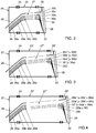
- Fig. 2 shows a ventilating device comprising a first part 21, a second part 22 and an intermediate part 23, which parts are coupled to each other by means of insulating elements 24.
- the first part 21 comprises an upper wall element 25 and a lower wall element 26, together bounding a part of the ventilating channel 27.
- Thinner lines indicate lower wall elements 26a-d, with which the height, and hence the passage, of the ventilating channel can be varied as required, the use of the upper wall element 25 and the lower wall element 26d yielding the smallest passage of the ventilating channel 27.
- the second part 22 comprises a valve element 28, an upper wall element 29 and a lower wall element 30.
- thinner lines indicate lower wall elements 30a-d, with which the height, and hence the passage, of the ventilating channel can be varied as required, the dimensions of both the upper wall elements 25 and 29 and of the lower wall elements 26 and 30 being matched such that at all times a ventilating channel 27 is obtained which has a constant passage substantially throughout its length.
- Fig. 3 shows an extended variant of the embodiment according to Fig. 2.
- the first part 21 has been maintained in unchanged form, as is the second part 22 in its basic form.
- the intermediate part 23' has been extended relative to the intermediate part 23 in Fig. 2, so that the ventilating channel 27' has a greater length than the ventilating channel 27 and, accordingly, extends to a higher level in the second part 22, which calls for adjustment of upper wall element 29', which has a shorter vertical part than the upper wall element 29 in Fig. 2. Similar adjustments are required for the lower wall element 30'.
- the lower wall element 30a in Fig. 2 can be chosen for the lower wall element 30'.
- FIG. 3 the lower wall elements of Fig. 2 are shown in Fig. 3 in unchanged form as regards shape and dimensions.
- lower wall element 30 from Fig. 2 no longer usable, is shown as well, though now by means of a thin line, whilst for the same reason a lower wall element located in line with lower wall element 26d, to be arranged in the second part 28 in the case where the smallest channel passage is desired, has been omitted.
- the elements 30a', 30b' and 30c' in Fig. 3 are identical to the elements 30b, 30c and 30d, respectively, in Fig. 3.
- Fig. 4 shows a still further extended embodiment of the ventilating device, obtained by means of a further extended intermediate part 23'', the extension having been selected such that the lower wall element 30'' is identical to lower wall element 30a' in Fig. 3, and hence lower wall element 30b in Fig. 2. Also, the lower wall elements 30a'', 30b' and 30c are identical, as are lower wall elements 30b'', 30c' and 30d. Upper wall element 29'' has again been adjusted in vertical direction as a consequence of the extension of ventilating channel 27''.
- valve elements used may be of any other suitable type.
- the housing of the sound-damping ventilating device may additionally comprise further separate resonator compartments which are not filled or only partly filled with sound-damping material and are thus attuned to a specific frequency or frequency range to be damped.
- the upper wall of the ventilating channel has not been changed whilst the lower wall thereof has been varied.
Landscapes
- Engineering & Computer Science (AREA)
- Chemical & Material Sciences (AREA)
- Combustion & Propulsion (AREA)
- Mechanical Engineering (AREA)
- General Engineering & Computer Science (AREA)
- Civil Engineering (AREA)
- Structural Engineering (AREA)
- Building Environments (AREA)
- Duct Arrangements (AREA)
Applications Claiming Priority (4)
| Application Number | Priority Date | Filing Date | Title |
|---|---|---|---|
| NL9200692 | 1992-04-15 | ||
| NL9200692A NL191270C (nl) | 1992-04-15 | 1992-04-15 | Geluiddempende ventilatie-inriching voorzien van een balkvormig huis met een spleetvormig ventilatiekanaal. |
| NL9201998 | 1992-11-16 | ||
| NL9201998A NL9201998A (nl) | 1992-04-15 | 1992-11-16 | Geluiddempende ventilatie-inrichting met een langgerekt, blokvormig huis en een sleufvormig ventilatiekanaal. |
Publications (3)
| Publication Number | Publication Date |
|---|---|
| EP0566211A1 true EP0566211A1 (fr) | 1993-10-20 |
| EP0566211B1 EP0566211B1 (fr) | 1995-08-09 |
| EP0566211B2 EP0566211B2 (fr) | 1999-04-14 |
Family
ID=26646963
Family Applications (1)
| Application Number | Title | Priority Date | Filing Date |
|---|---|---|---|
| EP93201102A Expired - Lifetime EP0566211B2 (fr) | 1992-04-15 | 1993-04-15 | Dispositif de ventilation silencieux avec un boítier allongé et conduit de ventilation en forme de fente |
Country Status (3)
| Country | Link |
|---|---|
| EP (1) | EP0566211B2 (fr) |
| DE (1) | DE69300349T3 (fr) |
| NL (1) | NL9201998A (fr) |
Cited By (7)
| Publication number | Priority date | Publication date | Assignee | Title |
|---|---|---|---|---|
| NL1002145C2 (nl) * | 1996-01-22 | 1997-07-29 | Zwaan Adrianus J | Geluiddempende ventilatie-inrichting met een langgerekt, doosvormig huis en een sleufvormig ventilatiekanaal. |
| FR2768219A1 (fr) * | 1997-09-11 | 1999-03-12 | Nicoll Raccords Plastiques | Dispositif amortisseur acoustique pour entree d'air menagee dans la maconnerie d'un batiment |
| BE1013154A3 (nl) | 1999-11-25 | 2001-10-02 | Aralco Nv | Suskast. |
| CN1083962C (zh) * | 1997-06-16 | 2002-05-01 | 广东美的集团股份有限公司 | 流体管路的消声装置 |
| NL1029327C2 (nl) * | 2005-06-23 | 2006-12-28 | Alusta Natuurlijke Ventilatiet | Geluiddempende en ventilerende muurdoorvoer. |
| BE1020710A3 (nl) * | 2012-06-15 | 2014-04-01 | Renson Ventilation Nv | Verbeterde akoestische ventilatieinrichting. |
| EP4265971A1 (fr) * | 2022-04-21 | 2023-10-25 | Atlantic Climatisation et Traitement d'Air Industrie | Visière pare-pluie pour systeme de ventilation d'une habitation |
Families Citing this family (1)
| Publication number | Priority date | Publication date | Assignee | Title |
|---|---|---|---|---|
| CN107327646A (zh) * | 2017-05-27 | 2017-11-07 | 苏州吉利不锈钢制品有限公司 | 一种汇流块结构 |
Citations (2)
| Publication number | Priority date | Publication date | Assignee | Title |
|---|---|---|---|---|
| NL8301801A (nl) * | 1983-05-20 | 1984-12-17 | Ubbink Nederland Bv | Geluidgedempte ventilatiekast. |
| NL8702464A (nl) * | 1987-10-15 | 1989-05-01 | Zwaan Adrianus J | Werkwijze voor het in een kozijn aanbrengen van een geluiddempende ventilatiekast alsmede een ventilatiekast toe te passen bij een dergelijke werkwijze. |
-
1992
- 1992-11-16 NL NL9201998A patent/NL9201998A/nl not_active Application Discontinuation
-
1993
- 1993-04-15 DE DE69300349T patent/DE69300349T3/de not_active Expired - Lifetime
- 1993-04-15 EP EP93201102A patent/EP0566211B2/fr not_active Expired - Lifetime
Patent Citations (2)
| Publication number | Priority date | Publication date | Assignee | Title |
|---|---|---|---|---|
| NL8301801A (nl) * | 1983-05-20 | 1984-12-17 | Ubbink Nederland Bv | Geluidgedempte ventilatiekast. |
| NL8702464A (nl) * | 1987-10-15 | 1989-05-01 | Zwaan Adrianus J | Werkwijze voor het in een kozijn aanbrengen van een geluiddempende ventilatiekast alsmede een ventilatiekast toe te passen bij een dergelijke werkwijze. |
Cited By (11)
| Publication number | Priority date | Publication date | Assignee | Title |
|---|---|---|---|---|
| NL1002145C2 (nl) * | 1996-01-22 | 1997-07-29 | Zwaan Adrianus J | Geluiddempende ventilatie-inrichting met een langgerekt, doosvormig huis en een sleufvormig ventilatiekanaal. |
| GB2309776A (en) * | 1996-01-22 | 1997-08-06 | Zwaan Adrianus J | Sound-damping ventilating device |
| GB2309776B (en) * | 1996-01-22 | 1999-10-20 | Zwaan Adrianus J | Sound-damping ventilating device with an elongated box-shaped housing and a slotted ventilating channel |
| BE1013318A3 (nl) * | 1996-01-22 | 2001-12-04 | Zwaan Adrianus J | Geluiddempende ventilatie-inrichting met een langgerekt, doosvormig huis en een sleufvormig ventilatiekanaal. |
| CN1083962C (zh) * | 1997-06-16 | 2002-05-01 | 广东美的集团股份有限公司 | 流体管路的消声装置 |
| FR2768219A1 (fr) * | 1997-09-11 | 1999-03-12 | Nicoll Raccords Plastiques | Dispositif amortisseur acoustique pour entree d'air menagee dans la maconnerie d'un batiment |
| BE1013154A3 (nl) | 1999-11-25 | 2001-10-02 | Aralco Nv | Suskast. |
| NL1029327C2 (nl) * | 2005-06-23 | 2006-12-28 | Alusta Natuurlijke Ventilatiet | Geluiddempende en ventilerende muurdoorvoer. |
| BE1020710A3 (nl) * | 2012-06-15 | 2014-04-01 | Renson Ventilation Nv | Verbeterde akoestische ventilatieinrichting. |
| EP4265971A1 (fr) * | 2022-04-21 | 2023-10-25 | Atlantic Climatisation et Traitement d'Air Industrie | Visière pare-pluie pour systeme de ventilation d'une habitation |
| FR3134877A1 (fr) * | 2022-04-21 | 2023-10-27 | Atlantic Climatisation et Traitement d’Air Industrie | Visière pare-pluie pour système de ventilation d’une habitation |
Also Published As
| Publication number | Publication date |
|---|---|
| DE69300349D1 (de) | 1995-09-14 |
| EP0566211B2 (fr) | 1999-04-14 |
| NL9201998A (nl) | 1993-11-01 |
| DE69300349T3 (de) | 1999-09-02 |
| EP0566211B1 (fr) | 1995-08-09 |
| DE69300349T2 (de) | 1996-04-04 |
Similar Documents
| Publication | Publication Date | Title |
|---|---|---|
| EP0566211B1 (fr) | Dispositif de ventilation silencieux avec un boîtier allongé et conduit de ventilation en forme de fente | |
| US6450289B1 (en) | Noise attenuation device | |
| US2735351A (en) | abrahamsen | |
| JP2012195997A (ja) | 地上設置型変圧器装置 | |
| US6138424A (en) | Vent apparatus for attachment to a building structure | |
| EP0902514A1 (fr) | Construction d'armoire pour équipements électriques ou électroniques | |
| US20120211714A1 (en) | Fence system with insect barrier | |
| EP3584511A1 (fr) | Appareil d'aération pourvu de garniture de silencieux | |
| KR102273933B1 (ko) | 핀을 가지는 공명모듈 및 이를 이용한 방음벽 | |
| US6038821A (en) | Variable width sill support | |
| ES2556707T3 (es) | Marco de soporte para una puerta de corredera | |
| EP0165760B1 (fr) | Dispositif d'isolation acoustique | |
| EP0521584B1 (fr) | Dispositif de ventilation insonorisé | |
| EP1736081B1 (fr) | Boîte aux lettres | |
| EP1611393A1 (fr) | Tuteur de jardin | |
| GB2309776A (en) | Sound-damping ventilating device | |
| JP3639214B2 (ja) | 防音塀 | |
| DE202004004432U1 (de) | Fassadenelement für Zu- und Abluft | |
| NL9200692A (nl) | Geluiddempende ventilatie-inrichting met een langgerekt, blokvormig huis en een sleufvormig ventilatiekanaal. | |
| KR200239300Y1 (ko) | 선박용 루버창 | |
| CA2057626A1 (fr) | Persiennes a egouttement facile | |
| DE202019103526U1 (de) | Ventilationsvorrichtung für ein Kühlmöbel | |
| JPH0828926A (ja) | 送風機 | |
| DE102018102168A1 (de) | Elektrizitätszähler mit einer optischen Kommunikationsschnittstelle | |
| RU2003130076A (ru) | Вентиляция крыши оранжереи |
Legal Events
| Date | Code | Title | Description |
|---|---|---|---|
| PUAI | Public reference made under article 153(3) epc to a published international application that has entered the european phase |
Free format text: ORIGINAL CODE: 0009012 |
|
| AK | Designated contracting states |
Kind code of ref document: A1 Designated state(s): BE DE GB IE NL |
|
| 17P | Request for examination filed |
Effective date: 19931201 |
|
| 17Q | First examination report despatched |
Effective date: 19941202 |
|
| GRAA | (expected) grant |
Free format text: ORIGINAL CODE: 0009210 |
|
| AK | Designated contracting states |
Kind code of ref document: B1 Designated state(s): BE DE GB IE NL |
|
| REG | Reference to a national code |
Ref country code: IE Ref legal event code: FG4D Free format text: 64815 |
|
| REF | Corresponds to: |
Ref document number: 69300349 Country of ref document: DE Date of ref document: 19950914 |
|
| PLBQ | Unpublished change to opponent data |
Free format text: ORIGINAL CODE: EPIDOS OPPO |
|
| PLBI | Opposition filed |
Free format text: ORIGINAL CODE: 0009260 |
|
| PLAV | Examination of admissibility of opposition |
Free format text: ORIGINAL CODE: EPIDOS OPEX |
|
| 26 | Opposition filed |
Opponent name: DUCO VENTILATIERROOSTERS NV Effective date: 19960423 |
|
| PLBF | Reply of patent proprietor to notice(s) of opposition |
Free format text: ORIGINAL CODE: EPIDOS OBSO |
|
| PLAV | Examination of admissibility of opposition |
Free format text: ORIGINAL CODE: EPIDOS OPEX |
|
| NLR1 | Nl: opposition has been filed with the epo |
Opponent name: DUCO VENTILATIERROOSTERS NV |
|
| NLUE | Nl: licence registered with regard to european patents |
Effective date: 19960711 |
|
| PLBF | Reply of patent proprietor to notice(s) of opposition |
Free format text: ORIGINAL CODE: EPIDOS OBSO |
|
| PLAW | Interlocutory decision in opposition |
Free format text: ORIGINAL CODE: EPIDOS IDOP |
|
| PLAW | Interlocutory decision in opposition |
Free format text: ORIGINAL CODE: EPIDOS IDOP |
|
| PUAH | Patent maintained in amended form |
Free format text: ORIGINAL CODE: 0009272 |
|
| STAA | Information on the status of an ep patent application or granted ep patent |
Free format text: STATUS: PATENT MAINTAINED AS AMENDED |
|
| 27A | Patent maintained in amended form |
Effective date: 19990414 |
|
| AK | Designated contracting states |
Kind code of ref document: B2 Designated state(s): BE DE GB IE NL |
|
| NLR2 | Nl: decision of opposition | ||
| NLR3 | Nl: receipt of modified translations in the netherlands language after an opposition procedure | ||
| REG | Reference to a national code |
Ref country code: GB Ref legal event code: IF02 |
|
| PGFP | Annual fee paid to national office [announced via postgrant information from national office to epo] |
Ref country code: IE Payment date: 20030403 Year of fee payment: 11 |
|
| PG25 | Lapsed in a contracting state [announced via postgrant information from national office to epo] |
Ref country code: IE Free format text: LAPSE BECAUSE OF NON-PAYMENT OF DUE FEES Effective date: 20040415 |
|
| REG | Reference to a national code |
Ref country code: IE Ref legal event code: MM4A |
|
| NLS | Nl: assignments of ep-patents |
Owner name: ALUSTA NATUURLIJKE VENTILATIETECHNIEK B.V. Effective date: 20050607 |
|
| PGFP | Annual fee paid to national office [announced via postgrant information from national office to epo] |
Ref country code: DE Payment date: 20100423 Year of fee payment: 18 |
|
| PGFP | Annual fee paid to national office [announced via postgrant information from national office to epo] |
Ref country code: GB Payment date: 20100420 Year of fee payment: 18 |
|
| REG | Reference to a national code |
Ref country code: DE Ref legal event code: R119 Ref document number: 69300349 Country of ref document: DE |
|
| REG | Reference to a national code |
Ref country code: DE Ref legal event code: R119 Ref document number: 69300349 Country of ref document: DE |
|
| GBPC | Gb: european patent ceased through non-payment of renewal fee |
Effective date: 20110415 |
|
| PG25 | Lapsed in a contracting state [announced via postgrant information from national office to epo] |
Ref country code: GB Free format text: LAPSE BECAUSE OF NON-PAYMENT OF DUE FEES Effective date: 20110415 |
|
| PGFP | Annual fee paid to national office [announced via postgrant information from national office to epo] |
Ref country code: NL Payment date: 20120425 Year of fee payment: 20 Ref country code: BE Payment date: 20120418 Year of fee payment: 20 |
|
| REG | Reference to a national code |
Ref country code: NL Ref legal event code: V4 Effective date: 20130415 |
|
| BE20 | Be: patent expired |
Owner name: *ZWAAN ADRIANUS JACOBUS Effective date: 20130415 |
|
| PG25 | Lapsed in a contracting state [announced via postgrant information from national office to epo] |
Ref country code: DE Free format text: LAPSE BECAUSE OF NON-PAYMENT OF DUE FEES Effective date: 20111031 |