EP0566471B1 - Wischerarm für Kraftfahrzeuge - Google Patents
Wischerarm für Kraftfahrzeuge Download PDFInfo
- Publication number
- EP0566471B1 EP0566471B1 EP93400952A EP93400952A EP0566471B1 EP 0566471 B1 EP0566471 B1 EP 0566471B1 EP 93400952 A EP93400952 A EP 93400952A EP 93400952 A EP93400952 A EP 93400952A EP 0566471 B1 EP0566471 B1 EP 0566471B1
- Authority
- EP
- European Patent Office
- Prior art keywords
- wiper arm
- windscreen wiper
- shell
- hollow
- drive head
- Prior art date
- Legal status (The legal status is an assumption and is not a legal conclusion. Google has not performed a legal analysis and makes no representation as to the accuracy of the status listed.)
- Expired - Lifetime
Links
Images
Classifications
-
- B—PERFORMING OPERATIONS; TRANSPORTING
- B60—VEHICLES IN GENERAL
- B60S—SERVICING, CLEANING, REPAIRING, SUPPORTING, LIFTING, OR MANOEUVRING OF VEHICLES, NOT OTHERWISE PROVIDED FOR
- B60S1/00—Cleaning of vehicles
- B60S1/02—Cleaning windscreens, windows or optical devices
- B60S1/04—Wipers or the like, e.g. scrapers
- B60S1/32—Wipers or the like, e.g. scrapers characterised by constructional features of wiper blade arms or blades
- B60S1/34—Wiper arms; Mountings therefor
- B60S1/3425—Constructional aspects of the arm
- B60S1/3445—Joints between elements
- B60S1/3447—Joints between elements the elements being an arm piece and a link piece
-
- B—PERFORMING OPERATIONS; TRANSPORTING
- B60—VEHICLES IN GENERAL
- B60S—SERVICING, CLEANING, REPAIRING, SUPPORTING, LIFTING, OR MANOEUVRING OF VEHICLES, NOT OTHERWISE PROVIDED FOR
- B60S1/00—Cleaning of vehicles
- B60S1/02—Cleaning windscreens, windows or optical devices
- B60S1/04—Wipers or the like, e.g. scrapers
- B60S1/32—Wipers or the like, e.g. scrapers characterised by constructional features of wiper blade arms or blades
-
- B—PERFORMING OPERATIONS; TRANSPORTING
- B60—VEHICLES IN GENERAL
- B60S—SERVICING, CLEANING, REPAIRING, SUPPORTING, LIFTING, OR MANOEUVRING OF VEHICLES, NOT OTHERWISE PROVIDED FOR
- B60S1/00—Cleaning of vehicles
- B60S1/02—Cleaning windscreens, windows or optical devices
- B60S1/04—Wipers or the like, e.g. scrapers
- B60S1/32—Wipers or the like, e.g. scrapers characterised by constructional features of wiper blade arms or blades
- B60S1/34—Wiper arms; Mountings therefor
-
- B—PERFORMING OPERATIONS; TRANSPORTING
- B60—VEHICLES IN GENERAL
- B60S—SERVICING, CLEANING, REPAIRING, SUPPORTING, LIFTING, OR MANOEUVRING OF VEHICLES, NOT OTHERWISE PROVIDED FOR
- B60S1/00—Cleaning of vehicles
- B60S1/02—Cleaning windscreens, windows or optical devices
- B60S1/04—Wipers or the like, e.g. scrapers
- B60S1/32—Wipers or the like, e.g. scrapers characterised by constructional features of wiper blade arms or blades
- B60S1/34—Wiper arms; Mountings therefor
- B60S1/3425—Constructional aspects of the arm
- B60S1/3445—Joints between elements
- B60S1/345—Joints between elements the elements being a link piece and a mounting head
-
- B—PERFORMING OPERATIONS; TRANSPORTING
- B60—VEHICLES IN GENERAL
- B60S—SERVICING, CLEANING, REPAIRING, SUPPORTING, LIFTING, OR MANOEUVRING OF VEHICLES, NOT OTHERWISE PROVIDED FOR
- B60S1/00—Cleaning of vehicles
- B60S1/02—Cleaning windscreens, windows or optical devices
- B60S1/04—Wipers or the like, e.g. scrapers
- B60S1/32—Wipers or the like, e.g. scrapers characterised by constructional features of wiper blade arms or blades
- B60S1/34—Wiper arms; Mountings therefor
- B60S1/3463—Means to press blade onto screen
- B60S1/3465—Means to press blade onto screen with coil springs
- B60S1/3468—Mountings therefor
Definitions
- the present invention relates to a wiper arm, in particular for a motor vehicle.
- the invention relates more particularly to a wiper arm of the wiper comprising a clevis hinge on a drive head and a body of wiper arm which extends the clevis longitudinally and the free end of which is connected to a wiper blade.
- the wiper arm is generally made in three parts, the main longitudinal part of which is a flat iron which extends in a plane substantially parallel to the plane of oscillation of the wiper arm.
- ice when wiping for example a motor vehicle windshield. (See, for example, US-A-2,619,668).
- This fixing means is very insecure in the sense that the differences in manufacturing tolerances between the diameters of the tubular body and of the cylindrical portion can cause that during the brazing or welding operation the tubular body can move in the hollow cylindrical portion and the overall length of the wiper arm can no longer correspond to that desired.
- the object of the invention is to propose a design of a wiper arm which overcomes the disadvantages which come to be mentioned while retaining satisfactory mechanical characteristics and reliability.
- the invention provides a wiper arm of the type disclosed in US-A-4,477,940 and as defined in the preamble of claim 1, characterized in that the hollow cylindrical portion of the articulation yoke is produced in the form of an elastically deformable portion radially to form a clamp for said end after the introduction of the latter into said portion.
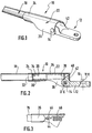
- FIGS. 1 and 2 recognize a wiper arm 10 which is mounted articulated with respect to a drive head 12 about an axis of articulation 14.
- the axis of rotation XX of the articulation axis 14 extends in a direction substantially perpendicular to the general longitudinal direction of the wiper arm 10 and perpendicular to the geometric axis YY of the bore 16 which is provided for receive a head drive shaft 12.
- the wiper arm 10 essentially consists of a hollow tubular longitudinal body 18.
- the body 18 is for example constituted by a cylindrical sheet metal tube.
- the end portion 20 of the tubular body 18 is connected to the drive head 12 by means of a yoke 22 which, in the embodiment illustrated in Figures 1 and 2, is a piece of folded and cut sheet metal.
- the yoke 22 essentially consists of a hollow cylindrical front portion which is extended axially towards the rear by two parallel lateral cheeks 26 and 28 which are perpendicular to the axis X-X.
- the side cheeks 26 and 28 receive the ends of the hinge pin 14 so that the yoke 22 is pivotally mounted relative to the drive head 12 around the axis X-X.
- the hollow cylindrical front portion 24 constitutes a clamp for the end 20 of the tubular body 18.
- the cylindrical portion 24 may for example have for this purpose a longitudinal slot 30 in order to facilitate the introduction of the end 20 of the tubular body 18 by radial elastic deformation of the cylindrical portion 24.
- the fixing of the end 20 can be completed by a welding operation.
- the end portion 20 comprises an internal radial shoulder 32 which is produced by deformation of the tubular wall of the longitudinal body 18 and which constitutes a support for the first end 34 of a helical compression spring 36.
- the second end 38 of the helical compression spring 36 bears against a seat 40 formed in a portion 42 of the drive head 12, located above the axis X-X.
- the function of the helical spring 36 is to permanently apply a nominal wiping torque to the wiper arm 10, around the articulation axis 14, which urges it counterclockwise when considering FIG. 2.
- the end 20 of the longitudinal tubular body 18 comprises a flattened portion 44 in which the first end 46 of a helical tension spring 48 is hooked, the other end of which (not shown) is intended to be hung on a corresponding portion of the drive head in order, according to the same principle as above, to apply to the wiper arm 10 a nominal wiping torque.
- the free end (not shown) of the tubular body 18 which must be connected to a wiper blade, can be flattened, as in the case of the end 44, in order to give it a rectangular cross section similar to that that has a flat iron arm, in order to allow its attachment to the wiper blade with known means for hooking the ends of the flat iron arms.
- the figures described so far represent a hollow tubular element 18 of circular shape and it can be envisaged that this hollow tubular element may have, in section, any other shape such as that offering a good aerodynamic effect and in particular a section oblong or teardrop-shaped.
Landscapes
- Engineering & Computer Science (AREA)
- Mechanical Engineering (AREA)
- Pivots And Pivotal Connections (AREA)
- Springs (AREA)
Claims (6)
- Wischerarm (10) in der Ausführung mit einem Gabelgelenk (22) an einem Antriebskopf (12) und einem rohrförmigen Wischerarmkörper (18), der in Längsrichtung das Gabelgelenk verlängert und dessen freies Ende mit einem Wischerblatt verbunden ist, wobei das besagte Gabelgelenk (22) einen hohlzylindrischen Abschnitt (24) umfaßt, der ein Ende (20) des rohrförmigen Hohlkörpers (18) aufnimmt , dadurch gekennzeichnet, daß der hohlzylindrische Abschnitt (24) des Gabelgelenks (22) in Form eines radial elastisch verformbaren Abschnitts ausgeführt ist, um einen Klemmbügel für das Festklemmen des besagten Endes (20) nach seiner Einführung in den besagten Abschnitt (24) zu bilden.
- Wischerarm nach Anspruch 1 ,dadurch gekennzeichnet, daß das Gabelgelenk (22) einstückig aus gestanztem und gebogenem Blech ausgeführt ist.
- Wischerarm nach Anspruch 1 oder 2 , dadurch gekennzeichnet, daß der hohlzylindrische Abschnitt (24) des Gabelgelenks (22) durch zwei parallele Seitenflächen (26, 28) verlängert wird, zwischen denen sich ein Gelenkbolzen (14) für die Anlenkung des Gabelgelenks (24) am Antriebskopf (12) des Scheibenwischers erstreckt.
- Wischerarm nach einem der vorangehenden Ansprüche, dadurch gekennzeichnet, daß der rohrförmige Hohlkörper (18) eine radiale Innenschulter (32) umfaßt, die in der Nähe des Gabelgelenks (22) angeordnet ist und die mit einem ersten Ende (34) einer Schraubendruckfeder (36) zusammenwirkt, die teilweise im Innern des rohrförmigen Hohlkörpers eingesetzt ist und deren zweites Ende (38) mit einem dem Antriebskopf (12) gegenüberliegenden Abschnitt (40) zusammenwirkt, um auf den Wischerarm (10) ein Wischmoment anzuwenden, das ihn drehend um den Gelenkbolzen (14) beansprucht.
- Wischerarm nach Anspruch 4 , dadurch gekennzeichnet, daß die radiale Innenschulter (32) durch radiale Verformung der rohrförmigen Wand des Längshohlkörpers (18) nach innen ausgeführt ist.
- Wischerarm nach einem der Ansprüche 1 bis 3 , dadurch gekennzeichnet, daß das Ende (20) des rohrförmigen Hohlkörpers (18), das in das Gabelgelenk eingesetzt ist, Mittel (44) für die Anbringung eines ersten Endes (46) einer Schraubenzugfeder (48) umfaßt, deren anderes Ende an einem Abschnitt des Antriebskopfes angebracht ist, um auf den Wischerarm (10) ein Wischmoment anzuwenden, das ihn drehend um den Gelenkbolzen beansprucht.
Applications Claiming Priority (2)
| Application Number | Priority Date | Filing Date | Title |
|---|---|---|---|
| FR9204560 | 1992-04-14 | ||
| FR9204560A FR2689839B1 (fr) | 1992-04-14 | 1992-04-14 | Bras d'essuie-glace de vehicule automobile. |
Publications (2)
| Publication Number | Publication Date |
|---|---|
| EP0566471A1 EP0566471A1 (de) | 1993-10-20 |
| EP0566471B1 true EP0566471B1 (de) | 1996-03-06 |
Family
ID=9428845
Family Applications (1)
| Application Number | Title | Priority Date | Filing Date |
|---|---|---|---|
| EP93400952A Expired - Lifetime EP0566471B1 (de) | 1992-04-14 | 1993-04-13 | Wischerarm für Kraftfahrzeuge |
Country Status (3)
| Country | Link |
|---|---|
| EP (1) | EP0566471B1 (de) |
| DE (1) | DE69301676T2 (de) |
| FR (1) | FR2689839B1 (de) |
Families Citing this family (5)
| Publication number | Priority date | Publication date | Assignee | Title |
|---|---|---|---|---|
| DE19825529A1 (de) * | 1998-06-08 | 1999-12-16 | Bosch Gmbh Robert | Wischerarm |
| FR2838090B1 (fr) * | 2002-04-05 | 2004-09-17 | Valeo Systemes Dessuyage | Bras d'essuie-glace realise a partir d'un troncon de profile tubulaire |
| DE10311783A1 (de) * | 2003-03-18 | 2004-09-30 | Robert Bosch Gmbh | Gelenkarm mit einer Wischstange |
| DE102006004110A1 (de) | 2006-01-28 | 2007-08-16 | Valeo Systèmes d`Essuyage | Wischarm |
| CN107672561A (zh) * | 2017-11-08 | 2018-02-09 | 丹阳镇威汽配有限公司 | 雨刮臂连接器 |
Family Cites Families (3)
| Publication number | Priority date | Publication date | Assignee | Title |
|---|---|---|---|---|
| US2619668A (en) * | 1947-04-19 | 1952-12-02 | King Seeley Corp | Windshield wiper mechanism |
| US4477940A (en) * | 1983-08-18 | 1984-10-23 | The Anderson Company Of Indiana | Heavy duty wiper arm |
| JPH0529179Y2 (de) * | 1987-12-11 | 1993-07-27 |
-
1992
- 1992-04-14 FR FR9204560A patent/FR2689839B1/fr not_active Expired - Fee Related
-
1993
- 1993-04-13 EP EP93400952A patent/EP0566471B1/de not_active Expired - Lifetime
- 1993-04-13 DE DE69301676T patent/DE69301676T2/de not_active Expired - Fee Related
Also Published As
| Publication number | Publication date |
|---|---|
| FR2689839A1 (fr) | 1993-10-15 |
| DE69301676T2 (de) | 1996-07-18 |
| EP0566471A1 (de) | 1993-10-20 |
| DE69301676D1 (de) | 1996-04-11 |
| FR2689839B1 (fr) | 1998-04-10 |
Similar Documents
| Publication | Publication Date | Title |
|---|---|---|
| EP2027000A1 (de) | Vorrichtung zur befestigung eines scheibenwischerblattes an einem arm | |
| WO2004024520A1 (fr) | Agencement de fixation d'un balai d'essuie glace sur un bras | |
| EP0579550B1 (de) | Scheibenwischerarm | |
| EP0584018B1 (de) | Scheibenwischer mit verbessertem Befestigungsteil | |
| EP0479659B1 (de) | Scheibenwischerarm besonders für Kraftfahrzeuge | |
| EP0519826B1 (de) | Scheibenwischer für ein Kraftfahrzeug, versehen mit einem aerodynamischen Windabweiser | |
| EP0566471A1 (de) | Wischerarm für Kraftfahrzeuge | |
| EP0491603B1 (de) | Verbindungsglied zwischen einem Scheibenwischerarm, insbesondere für Kraftfahrzeug | |
| EP4028292B1 (de) | Kurbelzapfen, kugelgelenk und entsprechendes scheibenwischerbetätigungsgestängesystem und verfahren zu dessen zusammenbau | |
| BE1001062A5 (fr) | Bras moteur pour balais d'essuie-glace avec ressort helicoidal a torsion. | |
| EP0575241B1 (de) | Gelenkverbindung zwischen dem gehäuseartigen Gelenkteil und dem Befestigungsteil eines Scheibenwischers | |
| FR2737691A1 (fr) | Retroviseur exterieur de vehicules automobiles | |
| EP0951411A1 (de) | Scheibenwischer für ein kraftfahrzeug mit einer feder zur erzeugung eines wischdruckes | |
| FR2746744A1 (fr) | Bras d'essuie-glace, notamment pour vehicule automobile | |
| FR2849885A1 (fr) | Perfectionnement aux dispositifs de liaison entre un verrou de porte et une serrure pour vehicule automobile | |
| EP3375675B1 (de) | Abdeckung, verbindungsvorrichtung für die montage eines scheibenwischerblatts auf einem entsprechenden scheibenwischerarm, und entsprechendes scheibenwischsystem | |
| FR2838090A1 (fr) | Bras d'essuie-glace realise a partir d'un troncon de profile tubulaire | |
| FR2534206A1 (fr) | Essuie-glace comportant une fixation simplifiee du bras par rapport a sa chape d'entrainement | |
| EP0664247B1 (de) | Kraftfahrzeugscheibenwischer mit aerodynamischem Windabweiser | |
| FR2523529A1 (fr) | Retroviseur exterieur a position stable de rabattement et a commande depuis l'interieur d'un vehicule automobile | |
| EP0688925A1 (de) | Drehriegel mit verbesserter Verbindungsvorrichtung | |
| EP0589798A1 (de) | Scheibenwischerarm mit geformtem Gelenkteil, insbesondere für Kraftfahrzeuge | |
| FR2770474A1 (fr) | Essuie-glace de vehicule automobile comportant des moyens perfectionnes d'articulation d'un balai d'essuie-glace sur un bras d'essuie-glace | |
| EP0637530A1 (de) | Scheibenwischer mit zwischen zwei auf dem Befestigungsteil vorgehesenen Seitenwangen eingesetztem Gelenkteil | |
| FR2746743A1 (fr) | Bras d'essuie-glace, notamment pour vehicule automobile |
Legal Events
| Date | Code | Title | Description |
|---|---|---|---|
| PUAI | Public reference made under article 153(3) epc to a published international application that has entered the european phase |
Free format text: ORIGINAL CODE: 0009012 |
|
| AK | Designated contracting states |
Kind code of ref document: A1 Designated state(s): DE ES GB IT |
|
| 17P | Request for examination filed |
Effective date: 19940408 |
|
| 17Q | First examination report despatched |
Effective date: 19950310 |
|
| GRAA | (expected) grant |
Free format text: ORIGINAL CODE: 0009210 |
|
| AK | Designated contracting states |
Kind code of ref document: B1 Designated state(s): DE ES GB IT |
|
| PG25 | Lapsed in a contracting state [announced via postgrant information from national office to epo] |
Ref country code: IT Free format text: LAPSE BECAUSE OF FAILURE TO SUBMIT A TRANSLATION OF THE DESCRIPTION OR TO PAY THE FEE WITHIN THE PRE;WARNING: LAPSES OF ITALIAN PATENTS WITH EFFECTIVE DATE BEFORE 2007 MAY HAVE OCCURRED AT ANY TIME BEFORE 2007. THE CORRECT EFFECTIVE DATE MAY BE DIFFERENT FROM THE ONE RECORDED.SCRIBED TIME-LIMIT Effective date: 19960306 Ref country code: ES Free format text: THE PATENT HAS BEEN ANNULLED BY A DECISION OF A NATIONAL AUTHORITY Effective date: 19960306 |
|
| REF | Corresponds to: |
Ref document number: 69301676 Country of ref document: DE Date of ref document: 19960411 |
|
| GBT | Gb: translation of ep patent filed (gb section 77(6)(a)/1977) |
Effective date: 19960416 |
|
| PLBE | No opposition filed within time limit |
Free format text: ORIGINAL CODE: 0009261 |
|
| STAA | Information on the status of an ep patent application or granted ep patent |
Free format text: STATUS: NO OPPOSITION FILED WITHIN TIME LIMIT |
|
| 26N | No opposition filed | ||
| PGFP | Annual fee paid to national office [announced via postgrant information from national office to epo] |
Ref country code: GB Payment date: 19970326 Year of fee payment: 5 |
|
| PGFP | Annual fee paid to national office [announced via postgrant information from national office to epo] |
Ref country code: DE Payment date: 19970618 Year of fee payment: 5 |
|
| PG25 | Lapsed in a contracting state [announced via postgrant information from national office to epo] |
Ref country code: GB Free format text: LAPSE BECAUSE OF NON-PAYMENT OF DUE FEES Effective date: 19980413 |
|
| GBPC | Gb: european patent ceased through non-payment of renewal fee |
Effective date: 19980413 |
|
| PG25 | Lapsed in a contracting state [announced via postgrant information from national office to epo] |
Ref country code: DE Free format text: LAPSE BECAUSE OF NON-PAYMENT OF DUE FEES Effective date: 19990202 |