EP0637530A1 - Scheibenwischer mit zwischen zwei auf dem Befestigungsteil vorgehesenen Seitenwangen eingesetztem Gelenkteil - Google Patents
Scheibenwischer mit zwischen zwei auf dem Befestigungsteil vorgehesenen Seitenwangen eingesetztem Gelenkteil Download PDFInfo
- Publication number
- EP0637530A1 EP0637530A1 EP93402018A EP93402018A EP0637530A1 EP 0637530 A1 EP0637530 A1 EP 0637530A1 EP 93402018 A EP93402018 A EP 93402018A EP 93402018 A EP93402018 A EP 93402018A EP 0637530 A1 EP0637530 A1 EP 0637530A1
- Authority
- EP
- European Patent Office
- Prior art keywords
- casing
- drive head
- wiper device
- flanges
- engaged
- Prior art date
- Legal status (The legal status is an assumption and is not a legal conclusion. Google has not performed a legal analysis and makes no representation as to the accuracy of the status listed.)
- Withdrawn
Links
- 230000000717 retained effect Effects 0.000 claims description 5
- 125000006850 spacer group Chemical group 0.000 claims description 5
- 241001417935 Platycephalidae Species 0.000 description 1
- 230000015572 biosynthetic process Effects 0.000 description 1
- 238000005260 corrosion Methods 0.000 description 1
- 230000007797 corrosion Effects 0.000 description 1
- 238000000034 method Methods 0.000 description 1
Images

Classifications
-
- B—PERFORMING OPERATIONS; TRANSPORTING
- B60—VEHICLES IN GENERAL
- B60S—SERVICING, CLEANING, REPAIRING, SUPPORTING, LIFTING, OR MANOEUVRING OF VEHICLES, NOT OTHERWISE PROVIDED FOR
- B60S1/00—Cleaning of vehicles
- B60S1/02—Cleaning windscreens, windows or optical devices
- B60S1/04—Wipers or the like, e.g. scrapers
- B60S1/32—Wipers or the like, e.g. scrapers characterised by constructional features of wiper blade arms or blades
- B60S1/34—Wiper arms; Mountings therefor
- B60S1/3425—Constructional aspects of the arm
- B60S1/3445—Joints between elements
- B60S1/345—Joints between elements the elements being a link piece and a mounting head
-
- B—PERFORMING OPERATIONS; TRANSPORTING
- B60—VEHICLES IN GENERAL
- B60S—SERVICING, CLEANING, REPAIRING, SUPPORTING, LIFTING, OR MANOEUVRING OF VEHICLES, NOT OTHERWISE PROVIDED FOR
- B60S1/00—Cleaning of vehicles
- B60S1/02—Cleaning windscreens, windows or optical devices
- B60S1/04—Wipers or the like, e.g. scrapers
- B60S1/32—Wipers or the like, e.g. scrapers characterised by constructional features of wiper blade arms or blades
- B60S1/34—Wiper arms; Mountings therefor
Definitions
- the present invention relates to the field of wiper devices, and more particularly wiper devices for wiping a windshield of a motor vehicle.
- Wiper devices which comprise a drive head capable of being coupled in rotation with a drive shaft and a wiper arm comprising a casing, articulated by one end on said head. drive around a deflection axis extending transversely to said drive shaft, extended at the other end by a brush-holder rod engaged in the casing and carrying a wiper blade adapted to come into contact with a surface to wipe.
- FIG. 1A shows a drive head 1, comprising a first bore 2 intended to receive a drive shaft not shown and a second bore 3, of axis perpendicular to the first, intended to receive a rivet 4 serving as a pivot at the articulation on the drive head 1 of a casing 5 partially shown.
- the housing 5 has a cross section generally having the shape of an inverted U, comprising two lateral wings 12 connected to a back. Two holes 6 and 7 are provided in the lateral wings 12 facing each other to receive the rivet 4.
- a plastic cap 8 covers the drive head 1, this cap 8 being placed on the drive head when the casing 5 is assembled thereon, and comprises two tabs 9 and 10 arranged inside the casing, each provided with an opening 11 intended for the passage of the rivet 4.
- the cap 8 is thus retained on the drive head 1 by means of the tabs 9 and 10 during the riveting of the casing 5 on the drive head 1.
- the tabs 9 and 10 made of plastic, and therefore relatively fragile, risk being damaged if the openings 11 are incorrectly positioned opposite the holes 6 and 7 of the casing, by pinching between the lateral wings 12 of the casing and the body of the drive head 1.
- the present invention relates to an improved wiper device, overcoming the aforementioned drawbacks.
- the present invention therefore provides, and according to a first characteristic of the invention, a wiper device comprising a drive head capable of being driven in rotation about a drive axis, a casing articulated to a first end on this drive head around a deflection axis extending transversely to said drive axis and provided, at its second end with a brush-carrying rod supporting a brush adapted to come into contact with a surface wiping, in which the drive head comprises two flanges between which extends a pin along said axis of movement, the first end of the housing extending between these two flanges to articulate on said pin.
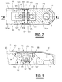
- a wiper device comprising a drive head 110, adapted to be coupled in rotation with a drive shaft not shown around a drive axis E, s 'extending perpendicular to the plane of Figure 2, and a wiper arm housing, referenced as a whole 100, articulated on the drive head at a first end about a deflection axis D extending transversely said drive axis E and contained in the cutting plane of FIG. 2.
- the drive head 110 has a flattened part 110a crossed by a bore 111 of axis E and of conical bearing capable of receiving a drive shaft known in itself and not shown.
- the housing 100 is provided at its other end with a brush-holder rod known in itself and therefore not shown, supporting a brush also known in itself, adapted to come into contact with a surface to be wiped.
- the casing 100 has a cross section generally having the shape of an inverted U, comprising two lateral wings 100a and 100b connected to a back 101. Reference will be made below for 102 the external surface of the back 101 and for 103 the internal surface of the back 101, extending between the lateral wings 100a and 100b.
- the wiper device comprises a cap 115, generally made of plastic, which covers the drive head and the first end of the hinged casing on this drive head.
- the cap 115 is advantageously retained in place on the drive head 110 by complementarity of shapes between first mounting means provided on the inner surface of the cap and second mounting means located on the outer surface of the drive head.
- the first mounting means consist of cylindrical housings 117 provided facing each other on the internal surface of the cap. 115, suitable for receiving second mounting means constituted by cylindrical bulges 127 projecting from the external surface of the drive head 110, these cylindrical bulges 127 bordering the external openings of the bores 113 supporting the axial ends of the journal 121.
- the connection between the cap 115 and the drive head 110 thus advantageously allows the cap 115 to be manually driven in rotation about the axis of movement D in order to free access to the connection between the drive head 110 and the drive shaft of the wiper device.
- the first end of the casing articulated on the drive head extends between the two flanges 112a and 112b to articulate on the pin 121.
- the back 101 of the casing 100 extends alone, at the level of the first end of the casing, in front of the wings lateral 100a and 100b to form a tab 106 comprising articulation means on the pin 121.
- these articulation means are constituted in the case of FIGS. 2 and 3 by an intermediate piece 120 attached to the lower surface 103 of paw 106 of the casing and traversed by a bore 107 in which the pin 121 is engaged.
- the articulation means could be formed by folding the tab 106 on itself to provide a housing in which the pin 121 would be engaged.
- the tab 106 of the casing 100 is connected to the back 102 of the casing by an oblique portion 104 oriented downwards and the tab 106 extends between the flanges of the drive head set back from the plane of the upper surface 102 of the back of the casing 100, so as to provide a space 105 in which is placed the upper wall of the cap 115, so presenting an external surface 116 situated in the extension of the upper surface 102 of the back of the casing; an aesthetic connection is thus obtained between the casing 100 and the drive head 110.
- the intermediate piece 120 is fixed under the tab 106 and matches the lower surface 103 thereof, also comes to be applied under the oblique part 104 and under a part of the back 101 adjacent to the oblique part 104
- the intermediate piece 120 is fixed under the tab 106 of the casing by means of two rivets 123 and 124 engaged at one end in holes provided for this purpose in the tab 106 of the casing and retained at the other end in housings 122 provided in the intermediate part 120, these housings opening onto the lower part of the intermediate part 120.
- the bore 107 serves as a housing for a cylindrical sleeve 125 serving as a bearing for the journal 121.
- the lateral wings 100a and 100b cover the free ends of the flanges 112a and 112b so that the external surface of the lateral wings 100a and 100b of the casing 100 and the external surface of the lateral wall of the cap 115 are in alignment with one another.
- a cylindrical rod 126 extends transversely to the drive axis E between the two flanges 112a and 112b, this cylindrical rod 126 serving for the attachment of a contact pressure spring, not shown, acting between the drive head and the wiper arm, in order to press the blade on the surface to be wiped.
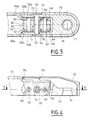
- the casing 100 has, from the free edge of its first end engaged between the flanges 112a and 112b of the drive head 110 of the portions 100'a and 100'b of lateral wings brought closer to each other by a distance less than the internal distance between the two flanges 112a and 112b.
- These portions 100'a and 100'b are provided with bores 130 located opposite one another in which is engaged the pin 121 serving as a pivot for the articulation of the casing 100 on the drive head 110.
- the pin 121 is preferably supported as shown by a sleeve 131 serving as a bearing, engaged in the bore 141 and in the holes 130, provided at its axial ends with a radial flange protruding radially on the external surface of the sleeve, and whose transverse flanks are interposed between the internal surface of the flanges 112a and 112b and the external surface of the close portions 100'a and 100'b of the lateral wings 100a and 100b.
- a sleeve 131 serving as a bearing, engaged in the bore 141 and in the holes 130, provided at its axial ends with a radial flange protruding radially on the external surface of the sleeve, and whose transverse flanks are interposed between the internal surface of the flanges 112a and 112b and the external surface of the close portions 100'a and 100'b of the lateral wings 100a and 100b.
- the part 140 forming a spacer is held between the two close portions 100'a and 100'b of the two lateral wings 100a and 100b of the casing 100 by means of two rivets 142 and 143 with flat heads arranged on either side of the central bore, these rivets 142 and 143 being engaged in bores 145 and 146 located in the plane containing the axis of travel D and perpendicular to the drive axis E.
- Corresponding holes 147 and 148 are provided opposite cylindrical openings of these bores 145 and 146 on the close portions 100'a and 100'b of the lateral wings of the casing.
- the external surface of the back of the end of the casing engaged between the flanges 112a and 112b extends back from the external surface of the back of the rest of the casing arranged in outside the drive head to provide a clearance 105 allowing the upper external surface of the cap to be located in line with the external surface of the back of the casing, it being understood that the close portions 100'a and 100'b of the casing 100 provide, facing their external surface, clearances in which the side wall of the cap 115 is positioned, so that the lateral external surface of the cap is also in line with the external surface of the side wings 100a and 100b of the casing 100 .
- the cap 115 is retained on the drive head 110 by complementarity of shapes between first molded mounting means of formation on the internal surface of the cap and second mounting means provided on the drive head. These first and second mounting means are identical to those of the first embodiment described above.
- a rod 126 for hooking a contact pressure spring is also provided, this contact pressure spring acting between the drive head and the arm of the wiper in order to press the blade on the surface to be wiped.
- a wiper device makes it possible to obtain an aesthetic connection between the drive head and the rest of the wiper device.
- the possibilities of corrosion are also reduced compared with devices according to the prior art in which the heads of the rivet serving as a pivot for the articulation protrude from the outer surface of the housing.
Landscapes
- Engineering & Computer Science (AREA)
- Mechanical Engineering (AREA)
- Pivots And Pivotal Connections (AREA)
Priority Applications (2)
| Application Number | Priority Date | Filing Date | Title |
|---|---|---|---|
| FR9209381A FR2694252B1 (fr) | 1992-07-29 | 1992-07-29 | Dispositif d'essuie-glace à carter inséré entre deux flasques prévus sur la tête d'entraînement. |
| EP93402018A EP0637530A1 (de) | 1992-07-29 | 1993-08-05 | Scheibenwischer mit zwischen zwei auf dem Befestigungsteil vorgehesenen Seitenwangen eingesetztem Gelenkteil |
Applications Claiming Priority (2)
| Application Number | Priority Date | Filing Date | Title |
|---|---|---|---|
| FR9209381A FR2694252B1 (fr) | 1992-07-29 | 1992-07-29 | Dispositif d'essuie-glace à carter inséré entre deux flasques prévus sur la tête d'entraînement. |
| EP93402018A EP0637530A1 (de) | 1992-07-29 | 1993-08-05 | Scheibenwischer mit zwischen zwei auf dem Befestigungsteil vorgehesenen Seitenwangen eingesetztem Gelenkteil |
Publications (1)
| Publication Number | Publication Date |
|---|---|
| EP0637530A1 true EP0637530A1 (de) | 1995-02-08 |
Family
ID=26134727
Family Applications (1)
| Application Number | Title | Priority Date | Filing Date |
|---|---|---|---|
| EP93402018A Withdrawn EP0637530A1 (de) | 1992-07-29 | 1993-08-05 | Scheibenwischer mit zwischen zwei auf dem Befestigungsteil vorgehesenen Seitenwangen eingesetztem Gelenkteil |
Country Status (2)
| Country | Link |
|---|---|
| EP (1) | EP0637530A1 (de) |
| FR (1) | FR2694252B1 (de) |
Cited By (2)
| Publication number | Priority date | Publication date | Assignee | Title |
|---|---|---|---|---|
| FR2762567A1 (fr) * | 1997-04-25 | 1998-10-30 | Valeo Systemes Dessuyage | Essuie-glace de vehicule automobile comportant des moyens de limitation du jeu apparent entre un bras d'essuie-glace et une tete d'entrainement |
| DE102015105628A1 (de) * | 2015-04-14 | 2016-10-20 | Valeo Systèmes d'Essuyage | Befestigungselement für einen Wischarm einer Scheibenwischanlage und Scheibenwischanlage mit einem Befestigungselement |
Citations (4)
| Publication number | Priority date | Publication date | Assignee | Title |
|---|---|---|---|---|
| FR1076875A (fr) * | 1953-05-12 | 1954-11-02 | Lucas Industries Ltd | Essuie-glace perfectionné pour véhicules |
| FR2462311A1 (fr) * | 1979-07-25 | 1981-02-13 | Marchal Equip Auto | Element d'essuie-glace, notamment pour vehicules automobiles |
| WO1983002094A1 (fr) * | 1981-12-11 | 1983-06-23 | Auzolat, Jean | Bras d'essuie-glace a ressort de compression |
| GB2117630A (en) * | 1982-04-02 | 1983-10-19 | Marchal Equip Auto | Stamped connector fitting for windscreen wiper-arm |
-
1992
- 1992-07-29 FR FR9209381A patent/FR2694252B1/fr not_active Expired - Fee Related
-
1993
- 1993-08-05 EP EP93402018A patent/EP0637530A1/de not_active Withdrawn
Patent Citations (4)
| Publication number | Priority date | Publication date | Assignee | Title |
|---|---|---|---|---|
| FR1076875A (fr) * | 1953-05-12 | 1954-11-02 | Lucas Industries Ltd | Essuie-glace perfectionné pour véhicules |
| FR2462311A1 (fr) * | 1979-07-25 | 1981-02-13 | Marchal Equip Auto | Element d'essuie-glace, notamment pour vehicules automobiles |
| WO1983002094A1 (fr) * | 1981-12-11 | 1983-06-23 | Auzolat, Jean | Bras d'essuie-glace a ressort de compression |
| GB2117630A (en) * | 1982-04-02 | 1983-10-19 | Marchal Equip Auto | Stamped connector fitting for windscreen wiper-arm |
Cited By (2)
| Publication number | Priority date | Publication date | Assignee | Title |
|---|---|---|---|---|
| FR2762567A1 (fr) * | 1997-04-25 | 1998-10-30 | Valeo Systemes Dessuyage | Essuie-glace de vehicule automobile comportant des moyens de limitation du jeu apparent entre un bras d'essuie-glace et une tete d'entrainement |
| DE102015105628A1 (de) * | 2015-04-14 | 2016-10-20 | Valeo Systèmes d'Essuyage | Befestigungselement für einen Wischarm einer Scheibenwischanlage und Scheibenwischanlage mit einem Befestigungselement |
Also Published As
| Publication number | Publication date |
|---|---|
| FR2694252A1 (fr) | 1994-02-04 |
| FR2694252B1 (fr) | 1994-11-04 |
Similar Documents
| Publication | Publication Date | Title |
|---|---|---|
| EP2027000A1 (de) | Vorrichtung zur befestigung eines scheibenwischerblattes an einem arm | |
| EP0579550B1 (de) | Scheibenwischerarm | |
| EP0584018B1 (de) | Scheibenwischer mit verbessertem Befestigungsteil | |
| CH627410A5 (fr) | Balai d'essuie-glace pour vehicules automobiles. | |
| FR2673151A1 (fr) | Bras d'essuie-glace, notamment pour vehicule automobile. | |
| EP0791514B1 (de) | Scheibenwischer für Kraftfahrzeuge mit Verkleidung für Endstück | |
| EP0575241B1 (de) | Gelenkverbindung zwischen dem gehäuseartigen Gelenkteil und dem Befestigungsteil eines Scheibenwischers | |
| EP2900525B1 (de) | Vorrichtung zur betätigung eines antriebsarms eines scheibenwischers, insbesondere für die heckscheibe eines kraftfahrzeuges, und wischsystem mit einer solchen vorrichtung | |
| FR2694252A1 (fr) | Dispositif d'essuie-glace à carter inséré entre deux flasques prévus sur la tête d'entraînement. | |
| EP0575242B1 (de) | Scheibenwischer mit Abdeckkappe, die am Befestigungsstift der Anpressfeder schwenkbar gelagert ist | |
| EP0443919A1 (de) | Scharnier mit integriertem Feststeller für Fahrzeugtüre oder andere Flügel | |
| EP0565437A1 (de) | Windableiter für Scheibenwischvorrichtung mit abnehmbarer weicher Kante | |
| FR3112736A1 (fr) | Balai d’essuie-glace comportant des moyens sécurisés de verrouillage sur un bras d’entraînement, et ensemble d’essuie-glace comportant un tel balai d’essuie-glace | |
| FR2598370A1 (fr) | Bras moteur pour balai d'essuie-glace avec ressort helicoidal a torsion | |
| EP0566471B1 (de) | Wischerarm für Kraftfahrzeuge | |
| FR2727918A1 (fr) | Dispositif d'essuie-glace pour vehicule automobile muni d'un capot d'habillage | |
| FR2838090A1 (fr) | Bras d'essuie-glace realise a partir d'un troncon de profile tubulaire | |
| FR2746744A1 (fr) | Bras d'essuie-glace, notamment pour vehicule automobile | |
| EP0591063B1 (de) | Scheibenwischer, inbesondere für eine Scheibe eines Autoscheinwerfers | |
| FR2848958A1 (fr) | Systeme de liaison d'un essuie-glace pour vitres de vehicules automobiles | |
| EP0567389B1 (de) | Wischarm mit wenigstens einer Anpressdruckfeder | |
| FR2754506A1 (fr) | Essuie-glace de vehicule automobile a moyen de rappel perfectionne | |
| EP0589798A1 (de) | Scheibenwischerarm mit geformtem Gelenkteil, insbesondere für Kraftfahrzeuge | |
| EP1728697A1 (de) | Anordnung eines Kraftfahrzeugs für die Halterung eines Zuführrohres für Waschflüssigkeit einer Windschutzscheibe | |
| FR2715367A1 (fr) | Essuie-glace pour véhicule automobile équipé d'un déflecteur aérodynamique. |
Legal Events
| Date | Code | Title | Description |
|---|---|---|---|
| PUAI | Public reference made under article 153(3) epc to a published international application that has entered the european phase |
Free format text: ORIGINAL CODE: 0009012 |
|
| AK | Designated contracting states |
Kind code of ref document: A1 Designated state(s): DE ES GB IT |
|
| 17P | Request for examination filed |
Effective date: 19950612 |
|
| 17Q | First examination report despatched |
Effective date: 19960709 |
|
| GRAG | Despatch of communication of intention to grant |
Free format text: ORIGINAL CODE: EPIDOS AGRA |
|
| GRAH | Despatch of communication of intention to grant a patent |
Free format text: ORIGINAL CODE: EPIDOS IGRA |
|
| GRAH | Despatch of communication of intention to grant a patent |
Free format text: ORIGINAL CODE: EPIDOS IGRA |
|
| RAP1 | Party data changed (applicant data changed or rights of an application transferred) |
Owner name: VALEO SYSTEMES D'ESSUYAGE |
|
| STAA | Information on the status of an ep patent application or granted ep patent |
Free format text: STATUS: THE APPLICATION IS DEEMED TO BE WITHDRAWN |
|
| 18D | Application deemed to be withdrawn |
Effective date: 19980303 |