EP0567005B1 - Dispositif de retardement pour une bobine - Google Patents
Dispositif de retardement pour une bobine Download PDFInfo
- Publication number
- EP0567005B1 EP0567005B1 EP93106200A EP93106200A EP0567005B1 EP 0567005 B1 EP0567005 B1 EP 0567005B1 EP 93106200 A EP93106200 A EP 93106200A EP 93106200 A EP93106200 A EP 93106200A EP 0567005 B1 EP0567005 B1 EP 0567005B1
- Authority
- EP
- European Patent Office
- Prior art keywords
- brake
- stem
- pressure chamber
- disc
- web tension
- Prior art date
- Legal status (The legal status is an assumption and is not a legal conclusion. Google has not performed a legal analysis and makes no representation as to the accuracy of the status listed.)
- Expired - Lifetime
Links
Images
Classifications
-
- B—PERFORMING OPERATIONS; TRANSPORTING
- B65—CONVEYING; PACKING; STORING; HANDLING THIN OR FILAMENTARY MATERIAL
- B65H—HANDLING THIN OR FILAMENTARY MATERIAL, e.g. SHEETS, WEBS, CABLES
- B65H23/00—Registering, tensioning, smoothing or guiding webs
- B65H23/04—Registering, tensioning, smoothing or guiding webs longitudinally
- B65H23/06—Registering, tensioning, smoothing or guiding webs longitudinally by retarding devices, e.g. acting on web-roll spindle
- B65H23/063—Registering, tensioning, smoothing or guiding webs longitudinally by retarding devices, e.g. acting on web-roll spindle and controlling web tension
-
- B—PERFORMING OPERATIONS; TRANSPORTING
- B65—CONVEYING; PACKING; STORING; HANDLING THIN OR FILAMENTARY MATERIAL
- B65H—HANDLING THIN OR FILAMENTARY MATERIAL, e.g. SHEETS, WEBS, CABLES
- B65H2403/00—Power transmission; Driving means
- B65H2403/70—Clutches; Couplings
- B65H2403/72—Clutches, brakes, e.g. one-way clutch +F204
- B65H2403/725—Brakes
- B65H2403/7255—Disc brakes
Definitions
- the invention relates to a delay device for a winding roll according to the preamble of claim 1.
- Such a deceleration device for a winding roll for regulating the web tension is known from DE-OS 23 44 591, which has a pendulum roller which senses the web tension and a control device for the braking force of a disc brake acting in the center of the winding roll which is influenced by its movement as a result of the change in the web tension, the brake blocks of which are actuated by a plunger of a working cylinder which rests on the end face of a membrane dividing a pressure chamber.
- the disadvantage of this device is that the braking force can only be increased in stages.
- the braking force required to maintain the web tension is reduced.
- the result of this is that, in particular in the case of simple control devices with the pendulum roller wrapped in dependence on the position of the web running off the winding roller, brakes which are largely proportionally controlled leave the pendulum roller with its winding roller diameter decreasing in its favorable working range.
- Another disadvantage of the known device is that the friction losses for guiding the tappet with the decrease in diameter of the running winding reel and thus inevitably reducing braking force have an increasingly disruptive effect on sensitive control of the web tension.
- the invention has for its object to design a delay device for a winding reel according to the preamble of claim 1 such that with simple technical means a favorable control behavior is ensured even with decreasing reel diameter and during the gluing process of the running web to the new winding reel.
- This solution has the advantage that due to the smooth transmission of the braking force by the plunger Falsification of the control is avoided and, on the other hand, the pendulum roller is located in a working area that is particularly favorable for the gluing process of the new winding roller due to the temporary application of a counterpressure to the working cylinder even with a low braking force.
- an adjustable throttle valve is arranged in its pressure medium supply line, so that the differential force counteracting the end-side pressure chamber takes effect with a delay.
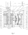
- each with a pressure medium connection 12; 13 provided pressure chambers 9; 10 once bounded by a membrane 15 clamped between a cover 14 of the housing 8 and on the other hand by a further membrane 16 fastened to the latter in the pressure chamber 10.
- both membranes 15; 16 is coaxially suspended from the housing 8 in a bore 17, a plunger 18 running smoothly, the diaphragm 15 clamped between the cover 14 of the housing 8 on the end of the plunger 18 and the second diaphragm 16 in the longitudinal direction axially offset circumferentially between a collar 19 and a detachable spacer 20 are clamped with the aid of a nut 21 which can be screwed onto a threaded attachment of the plunger 18.
- both sides of the brake disc 6 are each in the U-shaped, open towards the brake disc 6 recess 23 from a base 24; 25 and a glued brake pad 26; 27 existing brake block 28; 29 arranged. While the support 24 of the one brake pad 28, which is in direct contact with the tappet 18, is fastened to the spring band steel 30 screwed to the housing 8 by its elastic deformation, independently of the housing 8 in the direction of movement thereof, the other brake pad 29 is firmly screwed to the housing 8, so that in connection with the floating arrangement of the entire brake caliper 7, the braking force exerted by the plunger 18 via both brake pads 28; 29 is transmitted to the brake disc 6 on both sides.
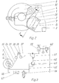
- Fig. 2 shows a schematic representation of the lateral arrangement of the two studs 2; 3 guided brake caliper 7 on the holding arm 1 for the winding roller, not shown.
- the latter is received by the spindle 4, which is mounted in a semicircular recess 31 in the holding arm 1 and secured by a pivoting lever 32 and which, together with the brake disc 6 attached to it, can be removed from the holder with the brake caliper 7 remaining on the holding arm 1.
- Fig. 3 shows the control loop for regulating the web tension.
- the web 34 running from the winding roller 33 wraps around the between two pull rollers 35; 36 arranged, mounted in a pivotable double lever 37 pendulum roller 38, which is loaded by a working cylinder 39 acting on the other end of the double lever with the setpoint value adjustable via an upstream pressure control valve 40 for the web tension.
- the changes in the web tension sensed by the pendulum roller 38 are transmitted via a control cam 41 attached to the double lever 37 thereof to the roller lever 42 of a pressure control valve 43 which is in connection with the pressure chamber 9 of the brake caliper 7 (FIG. 1) on the output side in the operating state.
- the pendulum roller 38 With a decreasing diameter of the running winding roll, the pendulum roller 38 leaves its favorable working area, which is necessary in particular for the gluing process of a new winding roll, due to the decreasing braking force transmitted by the plunger 18. This state is countered after reaching a predeterminable diameter of the winding roll with the running web 34 by switching on the annular pressure chamber 10, which produces a differential force counteracting the braking force, to the supply line 45 for the end-side pressure chamber 9 by means of a directional valve 44.
- a higher brake pressure to be newly adjusted via the pendulum roller is therefore required for the same braking force, as a result of which the pendulum roller 38 inevitably when the switch-off is switched off annular pressure chamber 10 connected, requiring a greater braking force sticking a new winding roller assumes a favorable working position for the control process.
Landscapes
- Controlling Rewinding, Feeding, Winding, Or Abnormalities Of Webs (AREA)
Claims (5)
- Dispositif de retardement destiné à une bobine afin de réguler la tension de bande, en particulier dans les presses rotatives, à l'aide d'un rouleau de tension détectant la tension de bande et d'un système de réglage, influencé par le mouvement de celui-ci par suite de la variation de la tension de bande, destiné à la force de freinage d'un frein à disque agissant au centre de la bobine, les patins de frein de celui-ci étant actionnés par un piston d'un cylindre de travail attenant du côté frontal à une membrane (15) cloisonnant une chambre de compression, caractérisé en ce que le piston (18) est accroché de manière axialement mobile sans frottement à cette membrane (15) ainsi que par celle-ci en décalage le long du piston (18) au moins à une membrane supplémentaire (16), qui cloisonne une chambre de compression annulaire (10) se mettant en circuit à l'admission du milieu de pression de celle-ci (45), produisant une force différentielle antagoniste dans la chambre de compression frontale (9).
- Dispositif selon la revendication 1, caractérisé en ce qu'une soupape d'étranglement réglable (47) est disposée dans l'admission du milieu de pression (46) de la chambre de compression annulaire (10).
- Dispositif selon la revendication 1, caractérisé en ce que les chambres de compression (9, 10) font directement partie d'un étrier de frein (7).
- Dispositif selon la revendication 3, caractérisé en ce que l'étrier de frein (7) muni des deux côtés de patins de frein (28, 29), en forme de U, recouvrant le disque de frein (6) est mobile perpendiculairement aux surfaces de freinage de celui-ci et en ce que le patin de frein (28) soumis à un effort par le piston (18) est articulé au bâti (8) de l'étrier de frein (7) de manière relativement souple dans le même sens par l'intermédiaire d'une lame de ressort (30).
- Dispositif selon la revendication 4, caractérisé en ce que le piston (18) s'appuie au bâti (8) de l'étrier de frein (7) en opposition à sa force de freinage exercée par l'intermédiaire d'un ressort de pression (22) circonférentiellement attenant à une collerette (19).
Applications Claiming Priority (2)
| Application Number | Priority Date | Filing Date | Title |
|---|---|---|---|
| DE4213052A DE4213052A1 (de) | 1992-04-21 | 1992-04-21 | Verzögerungsvorrichtung für eine Wickelrolle |
| DE4213052 | 1992-04-21 |
Publications (3)
| Publication Number | Publication Date |
|---|---|
| EP0567005A2 EP0567005A2 (fr) | 1993-10-27 |
| EP0567005A3 EP0567005A3 (fr) | 1995-05-24 |
| EP0567005B1 true EP0567005B1 (fr) | 1996-05-22 |
Family
ID=6457130
Family Applications (1)
| Application Number | Title | Priority Date | Filing Date |
|---|---|---|---|
| EP93106200A Expired - Lifetime EP0567005B1 (fr) | 1992-04-21 | 1993-04-16 | Dispositif de retardement pour une bobine |
Country Status (2)
| Country | Link |
|---|---|
| EP (1) | EP0567005B1 (fr) |
| DE (2) | DE4213052A1 (fr) |
Family Cites Families (5)
| Publication number | Priority date | Publication date | Assignee | Title |
|---|---|---|---|---|
| US2965326A (en) * | 1957-12-18 | 1960-12-20 | Cameron Machine Co | Apparatus for controlling tension in a web |
| US3289967A (en) * | 1964-06-01 | 1966-12-06 | Art I Robinson | Tension regulator |
| DE1574420C2 (de) * | 1967-04-28 | 1974-08-08 | Rolpa S.A.R.L., Carouge-Genf (Schweiz) | Vorrichtung zum Abrollen einer Bahn |
| SE366007B (fr) * | 1972-09-11 | 1974-04-08 | Wifag Maschf | |
| US3964692A (en) * | 1973-08-03 | 1976-06-22 | Mattco, Inc. | Winch spool with disc brake system |
-
1992
- 1992-04-21 DE DE4213052A patent/DE4213052A1/de not_active Withdrawn
-
1993
- 1993-04-16 EP EP93106200A patent/EP0567005B1/fr not_active Expired - Lifetime
- 1993-04-16 DE DE59302652T patent/DE59302652D1/de not_active Expired - Fee Related
Also Published As
| Publication number | Publication date |
|---|---|
| DE59302652D1 (de) | 1996-06-27 |
| EP0567005A2 (fr) | 1993-10-27 |
| EP0567005A3 (fr) | 1995-05-24 |
| DE4213052A1 (de) | 1993-10-28 |
Similar Documents
| Publication | Publication Date | Title |
|---|---|---|
| DE4409252C2 (de) | Luftfederungsanlage | |
| DE4222044C2 (de) | Hydraulische Scheibenbremse für Fahrräder oder dergleichen | |
| DE2631662C2 (de) | Vorrichtung zur Einleitung einer lastabhängigen Steuerkraft in ein Drucksteuerventil einer Fahrzeug-Bremsanlage | |
| CH659233A5 (de) | Vorrichtung zum aufwickeln eines schuppenstromes aus papierbogen. | |
| DE3001415C2 (fr) | ||
| EP1627159B1 (fr) | Frein a disque a actionnement par voie pneumatique ou par moteur electrique | |
| DE1555528C3 (de) | Bremsdruckverteiler für hydraulische Faftrzeug-Bremsanfagen | |
| EP0565997B1 (fr) | Frein à disque actionné par air comprimé | |
| EP0567005A2 (fr) | Dispositif de retardement pour une bobine | |
| DE3418041A1 (de) | Verfahren zur voreinstellung bzw. einstellung des umschaltpunktes einer bremsdrucksteuereinheit und bremsdrucksteuereinheit fuer eine druckmittelbetaetigbare fahrzeugbremsanlage | |
| DE1655066B2 (de) | Druckmindervorrichtung für ein Hydrauliksystem, insbesondere ein hydraulisches Kraftfahrzeug-Bremssystem | |
| DE2913506A1 (de) | Kraftverstaerker | |
| WO1993018948A1 (fr) | Servofrein a depression | |
| EP0382057B1 (fr) | Contrôle automatique du freinage en fonction de la charge | |
| DE1555541C3 (de) | Bremsdruckregler für Fahrzeuge | |
| EP0058413A1 (fr) | Régulateur de force de freinage commandé en fonction de la charge | |
| DE2435779C2 (de) | Druckmittelbremsanlage für Kraftfahrzeuge | |
| DE1013907B (de) | Druckmittelbetriebener Regler mit Rueckfuehrung | |
| DE2631651B2 (de) | Spielnachstelleinrichtung für Bremszylinder einer Bremsanlage bei Schienenfahrzeugen | |
| EP0090547A3 (fr) | Système de commande de frein et valve de commande | |
| DE2548351B2 (de) | Druckregelventil für eine Doppelachs-Luftfederung von Nutzfahrzeugen | |
| DE4136866C2 (de) | Pneumatisches Druckregelventil und dessen Verwendung | |
| DE3242588C2 (fr) | ||
| DE19860608A1 (de) | Drahtbremse für Spulenwickelmaschinen | |
| DE4110355C2 (de) | Lastabhängiger Bremskraftregler für Druckluftbremsanlagen in Fahrzeugen, insbesondere Nutzfahrzeugen |
Legal Events
| Date | Code | Title | Description |
|---|---|---|---|
| PUAI | Public reference made under article 153(3) epc to a published international application that has entered the european phase |
Free format text: ORIGINAL CODE: 0009012 |
|
| AK | Designated contracting states |
Kind code of ref document: A2 Designated state(s): CH DE FR GB IT LI SE |
|
| PUAL | Search report despatched |
Free format text: ORIGINAL CODE: 0009013 |
|
| AK | Designated contracting states |
Kind code of ref document: A3 Designated state(s): CH DE FR GB IT LI SE |
|
| 17P | Request for examination filed |
Effective date: 19950420 |
|
| 17Q | First examination report despatched |
Effective date: 19950718 |
|
| GRAH | Despatch of communication of intention to grant a patent |
Free format text: ORIGINAL CODE: EPIDOS IGRA |
|
| ITF | It: translation for a ep patent filed | ||
| GRAA | (expected) grant |
Free format text: ORIGINAL CODE: 0009210 |
|
| AK | Designated contracting states |
Kind code of ref document: B1 Designated state(s): CH DE FR GB IT LI SE |
|
| REG | Reference to a national code |
Ref country code: CH Ref legal event code: NV Representative=s name: E. BLUM & CO. PATENTANWAELTE |
|
| REF | Corresponds to: |
Ref document number: 59302652 Country of ref document: DE Date of ref document: 19960627 |
|
| GBT | Gb: translation of ep patent filed (gb section 77(6)(a)/1977) |
Effective date: 19960827 |
|
| ET | Fr: translation filed | ||
| PLBE | No opposition filed within time limit |
Free format text: ORIGINAL CODE: 0009261 |
|
| 26N | No opposition filed | ||
| REG | Reference to a national code |
Ref country code: GB Ref legal event code: IF02 |
|
| PGFP | Annual fee paid to national office [announced via postgrant information from national office to epo] |
Ref country code: CH Payment date: 20030318 Year of fee payment: 11 |
|
| PGFP | Annual fee paid to national office [announced via postgrant information from national office to epo] |
Ref country code: GB Payment date: 20030326 Year of fee payment: 11 |
|
| PGFP | Annual fee paid to national office [announced via postgrant information from national office to epo] |
Ref country code: DE Payment date: 20030331 Year of fee payment: 11 |
|
| PGFP | Annual fee paid to national office [announced via postgrant information from national office to epo] |
Ref country code: SE Payment date: 20030402 Year of fee payment: 11 |
|
| PGFP | Annual fee paid to national office [announced via postgrant information from national office to epo] |
Ref country code: FR Payment date: 20030408 Year of fee payment: 11 |
|
| PG25 | Lapsed in a contracting state [announced via postgrant information from national office to epo] |
Ref country code: GB Free format text: LAPSE BECAUSE OF NON-PAYMENT OF DUE FEES Effective date: 20040416 |
|
| PG25 | Lapsed in a contracting state [announced via postgrant information from national office to epo] |
Ref country code: SE Free format text: LAPSE BECAUSE OF NON-PAYMENT OF DUE FEES Effective date: 20040417 |
|
| PG25 | Lapsed in a contracting state [announced via postgrant information from national office to epo] |
Ref country code: LI Free format text: LAPSE BECAUSE OF NON-PAYMENT OF DUE FEES Effective date: 20040430 Ref country code: CH Free format text: LAPSE BECAUSE OF NON-PAYMENT OF DUE FEES Effective date: 20040430 |
|
| PG25 | Lapsed in a contracting state [announced via postgrant information from national office to epo] |
Ref country code: DE Free format text: LAPSE BECAUSE OF NON-PAYMENT OF DUE FEES Effective date: 20041103 |
|
| EUG | Se: european patent has lapsed | ||
| GBPC | Gb: european patent ceased through non-payment of renewal fee |
Effective date: 20040416 |
|
| REG | Reference to a national code |
Ref country code: CH Ref legal event code: PL |
|
| PG25 | Lapsed in a contracting state [announced via postgrant information from national office to epo] |
Ref country code: FR Free format text: LAPSE BECAUSE OF NON-PAYMENT OF DUE FEES Effective date: 20041231 |
|
| REG | Reference to a national code |
Ref country code: FR Ref legal event code: ST |
|
| PG25 | Lapsed in a contracting state [announced via postgrant information from national office to epo] |
Ref country code: IT Free format text: LAPSE BECAUSE OF NON-PAYMENT OF DUE FEES Effective date: 20050416 |