EP0567220A2 - Korrelation zwischen Cursorstelle und dargestellte Formen in einem Rechnersystem - Google Patents
Korrelation zwischen Cursorstelle und dargestellte Formen in einem Rechnersystem Download PDFInfo
- Publication number
- EP0567220A2 EP0567220A2 EP93301989A EP93301989A EP0567220A2 EP 0567220 A2 EP0567220 A2 EP 0567220A2 EP 93301989 A EP93301989 A EP 93301989A EP 93301989 A EP93301989 A EP 93301989A EP 0567220 A2 EP0567220 A2 EP 0567220A2
- Authority
- EP
- European Patent Office
- Prior art keywords
- shape
- bit map
- shapes
- bounding rectangle
- cursor
- Prior art date
- Legal status (The legal status is an assumption and is not a legal conclusion. Google has not performed a legal analysis and makes no representation as to the accuracy of the status listed.)
- Withdrawn
Links
Images
Classifications
-
- G—PHYSICS
- G06—COMPUTING OR CALCULATING; COUNTING
- G06F—ELECTRIC DIGITAL DATA PROCESSING
- G06F3/00—Input arrangements for transferring data to be processed into a form capable of being handled by the computer; Output arrangements for transferring data from processing unit to output unit, e.g. interface arrangements
- G06F3/01—Input arrangements or combined input and output arrangements for interaction between user and computer
- G06F3/048—Interaction techniques based on graphical user interfaces [GUI]
- G06F3/0484—Interaction techniques based on graphical user interfaces [GUI] for the control of specific functions or operations, e.g. selecting or manipulating an object, an image or a displayed text element, setting a parameter value or selecting a range
- G06F3/04842—Selection of displayed objects or displayed text elements
Definitions
- a conventional computer system processes are managed by an operating system such as DOS or OS/2, which in turn supports an application progam such as a word processor or spreadsheet.
- the application program is largely responsible for determining what input or output is necessary, but only communicates with the input/output devices via the operating system. Thus the application program might send a request for a particular output message to the operating system, which is then responsible for writing the message onto the output display screen.
- the actual display on the screen at any one time is determined by the contents of a hardware frame buffer.
- This buffer usually contains the actual pixel intensities and colours, although there can be another hardware logic processing stage between the frame buffer and the screen itself (for example the frame buffer may contain text strings which the logic then processes into pixel patterns).
- the operating system updates the frame buffer, and the output on the screen then alters accordingly.
- the frame buffer and logic are implemented in hardware because the data rate to the screen is very high (typically of the order of Megabytes per second) - this is also the reason that image processing imposes such large computing overheads.
- GUI graphical user interface
- the operating system monitors the physical movement of the mouse and translates this into the corresponding screen position of the cursor.
- the user presses a button on the mouse when the cursor coincides with that point.
- this user selection of a particular position is first received by the operating system before forwarding to the application program.
- the selected position might represent the user's choice of one of several icons or other shapes currently displayed on the screen. These shapes can represent for example files to be processed or components of a drawing to be manipulated.
- the present invention is concerned with the correlation of a cursor-selected position with the displayed shapes, to determine which shape (or shapes) the user has actually chosen. This correlation is sometimes provided by the operating system, but if not, the application program must do the correlation itself. In either case, the process must complete in a fraction of a second unless the user is to notice an intrusive delay.
- the bounding rectangle is defined as the smallest rectangle (with horizontal and vertical edges) that completely encloses a particular shape.
- the selected position is then correlated not against the shape itself but against the bounding rectangle instead. This approach is much simpler computationally and therefore faster, but can produce an incorrect correlation if the selected position is outside a particular shape, but within its associated bounding rectangle.
- the prior art therefore does not disclose an accurate but computationally efficient pick correlation facility to allow the computer to to determine which shape or shapes a user has selected.
- the present invention provides a method of correlating a cursor position with displayed shapes in a computer system including storage means, means for displaying the shapes and a cursor, and user input means for moving the cursor and selecting a cursor position;
- the present invention adopts a two-part approach to correlation, using bounding rectangles in a first pass for speed, followed by a second pass to maintain full accuracy whilst still minimising overall processing time.
- the examination of bounding rectangles in the first pass quickly eliminates shapes that are not close to the selected cursor position.
- the second pass then examines any remaining shapes, to provide an exact determination of correlation. This is achieved by re-drawing the remaining shapes into a specially created bit map in memory.
- the bit map is defined so as to correspond to a region of predetermined size around the selected cursor position. This select region, which is usually rectangular, is effectively a predefined margin of error that has been attributed to the user's positioning of the cursor.
- the bit map is small enough to keep in RAM, and so can be accessed quickly to determine which (if any) of the redrawn shapes have written pixels to it. Any shape that changes pixels in the bit map is considered to be correlated with the user's selected position. It is up to the designer of the calling procedure to decide what action to take if more than one shape (or zero) is found to be correlated.
- the method of the present invention can be implemented either as part of the computer operating system, or by an application program.
- bit map is created with one bit per pixel, as opposed to the several bytes per pixel of the screen image. All areas of a shape, whether partially shaded, or light or dark solid colour, are therefore effectively depicted in monochrome at a single intensity (black or zero is convenient). This simplified representation is quite sufficient to determine whether a shape overlaps the select region, is faster to re-draw, and requires far less storage than a bit map with several bytes per pixel.
- the step of determining whether a shape whose bounding rectangle overlaps the select region has been written to the bit map comprises reading the bit map after each shape has been drawn, and examining whether any bits in the map have been changed.
- the bit map is checked to see if any bits have been altered by drawing that shape. If any have, then that shape must overlap the select region, and so that shape is one that the user may have selected.
- a list can then be created of correlated shapes.
- each pixel in the bit map corresponds to three bytes of information (eg 255 intensity levels in each of three colours), so that each pixel has 24 bit positions associated with it.
- the first shape can be drawn into the first bit position, the second into the second, etc.
- the value for each pixel can then be read out and the correlated shapes uniquely determined from the bit positions that have been altered.
- This approach has the advantage of reading the bit map fewer times, but requires much larger storage space for the bit map and is limited in the number of shapes that it can handle.
- the steps of examining the bounding rectangle, drawing each shape, and examining the bit map are performed in succession for each shape.
- a different approach would be to first make a list of those shapes whose bounding rectangle intersects the select region, and then draw the shapes in this list into the bit map. This is less efficient if only a limited number of correlated shapes are to be detected because it calculates bounding rectangle intersections for every shape.
- the invention also provides a computer system including storage means, means for displaying shapes and a cursor, user input means for moving the cursor on the display means and for selecting a cursor position, and means for correlating the selected cursor position with displayed shapes;
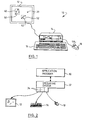
- Figure 1 illustrates a computer system 10 including a screen 12, processor unit 14, keyboard 16 and mouse 18. With the mouse, the user can change the position of a cursor 20 displayed on the screen. Typically input from the mouse and output to the screen are handled by BIOS code 34 (see Figure 2), which can be treated for present purposes as part of the operating system 32. The following description will assume that the correlation of the cursor position is performed by an application program, but it could equally well be implemented as part of the computer operating system.
- the application program calls an appropriate subroutine of the operating system, and passes to it various parameters specifying the shape to be drawn (size, position etc). Typically other subroutines might also be called, for example to initialise drawing operations.
- the subroutine calls and associated parameters that are available in the DOS Windows operating system from Microsoft Corporation are described in "The Microsoft Windows Software Development Kit Reference Vols 1 and 2" (Document Number SY0302a-300-ROO-1089) - analogous procedures exist in other programming environments.
- the operating system then sends appropriate commands to the device drivers to draw the requested shape on the screen.
- the application program works in pre-defined x-y coordinates, which the operating system translates into actual pixel positions.
- the application program When the application program requests a shape to be drawn on the screen, it also calculates the bounding rectangle for that particular shape. For shapes such as a circle or square it is very simple to determine the bounding rectangle. For arbitrary polygons, these can be represented as a plurality of lines, and the bounding rectangle for the polygon calculated relatively simply as the smallest rectangle that encloses the bounding rectangle of every line. For curves the bounding rectangle can either be obtained by a more sophisticated calculation, or by splitting the curve into a series of very short straight line segments and following the procedure for polygon. Bounding rectangles 50, 52 are shown in Figure 1 for shapes 40,42, although normally of course the bounding rectangles do not appear on the screen. It can be seen that the area of a bounding rectangle can be considerably more than that of the shape itself (especially if the shape represents a "line").
- the application program maintains a table containing an identification of each shape currently displayed on the screen, and also of the associated bounding rectangle.
- bounding rectangles are defined in terms of the X-Y coordinates of the bottom-left and top-right corners.
- the operating system When the user selects a particular position on the screen, normally using a button 118 on the mouse 18, the operating system returns to the application program the current position of the cursor20 (in x-y coordinates, rather than pixel coordinates). The application then converts this position into a pick rectangle around the cursor.
- the pick rectangle has horizontal and vertical edges centered on the exact cursor position and defines an area which it is assumed that the user has selected all of - any shape that overlaps any of the pick rectangle is correlated with the selected cursor position.
- the pick rectangle effectively gives the user some margin for error in positioning the cursor, which is particularly useful in attempting to select a small or narrow object, such as a line.
- the user can actually control the size of the pick rectangle, and indeed it is possible to use a 1x1 rectangle, in which case the cursor must lie on exactly the same pixel as the shape to be selected.
- the application program then examines each entry in its table of displayed shapes to see if the pick rectangle intersects the bounding rectangle of the shape.
- the process for determining whether two rectangles overlap is straightforward and well-known to the skilled man. Those shapes which are found to overlap the pick rectangle are then re-drawn. This is done by calling essentially same operating system subroutines as used to draw the shapes on the screen, but this time specifying (i) that the "screen" size is equal to that of the pick rectangle; (ii) that there is only one bit per pixel; and (ii) instead of drawing to the screen, the pixel values are to be written into a file in memory.
- the re-drawing can be performed very quickly because factors (i) and (ii) above mean that the effective size of the screen is very small. Thus any portions of a shape outside the pick rectangle (which is typically only 1% of the width of the full screen) are ignored, and the number of bits per pixel is also reduced. Any part of the shape, whether shaded or not, whatever its colour, is represented by a bit value of 1.
- the program After the shape has been drawn, the program requests the contents of the bit map back from the operating system (this is of course possible because the bit map has been written to memory rather than the screen).
- the bit map is examined to see if any of the bits have non-zero values. If the bit map contains only zeros, then the shape has not written to any pixels in the pick rectangle, and so that particular shape is not correlated with the selected cursor position. In other words, the selected cursor position lies inside the bounding rectangle of that shape, but outside the shape itself.
- the program can then go on to examine the bounding rectangle for the next displayed shape. If however a non-zero value is found (ie a bit set to 1), then this indicates that this particular shape has written to the bit map, and so overlaps the pick rectangle.
- This shape is therefore identified as being correlated with the selected cursor position.
- the bit map must now be reset to zero before the process can continue to search for other correlated shapes (unless of course the application program is only interested in first correlated shape). If more than one shape is found to be correlated with the selected cursor position, it is up to the application program to decide what action to take next - eg whether it accepts the multiple shapes, whether it wants the user to reselect, or whether it perhaps wants to repeat the above process using a smaller effective pick rectangle to hunt for the correlated shape closest to the actual cursor position.
- Table 1 gives a list of the Windows subroutines called, and a brief explanation of what each does.
- Table 2 gives a list of the Windows subroutines called, and a brief explanation of what each does.
- the first two sections of code in Table 1 set up parameters which are under the control of the application program -the size of the pick rectangle, and the maximum acceptable number of "hits" (ie shapes that are correlated with the cursor position). Normally the same values for these parameters are used for many correlations, and so their values will be preset before the correlation starts.
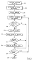
- the correlation proper begins with receipt of the selected cursor position 200 from the operating system, which allows the pick rectangle to be calculated in a straightforward manner 202.
- the bit map corresponding in size to the pick rectangle is then created 204 by sections 5-9 of the code of Table 1. Note that the bit map is created at the start of the correlation, and is thereafter available for each shape as required.
- a slight complication is that in Windows the memory allocated must be a whole number of words (a word is two bytes).
- the calculation for "bitwidth" in section 5 takes this into account (note that both "bitwidth” and "bitsize” are actually a number of bytes). As a result, the memory allocated may be slightly larger than the pick rectangle.
- the bounding rectangle of each displayed shape from the array "bound_rect" in section 11 is examined 206 to see whether it overlaps the pick rectangle 208, starting at the bottom of the array which corresponds to the most recently drawn shapes. If an overlap is found, the bit map is first cleared to zero 210 in case a previous shape has written to it, and then the shape is drawn into the bit map 212 using the function "draw- shape". This function masks off any part of the shape outside the pick rectangle (section 13) to speed up the correlation if the graphics engine of the operating system would otherwise process features outside the bit map before actually drawing the shape.
- the portion of memory holding the bit map is read out and checked (a byte at a time) to see if any bits have been altered from zero 214.
- the memory allocation for the bit map may be larger than the pick rectangle, the masking process of "draw shape" ensures that any bits outside the pick rectangle will be zero (alternatively the loop limits in section 15 could be adjusted appropriately so as to only search those bits actually in the pick rectangle). If any non-zero bits are found (section 16), then this indicates that the shape is correlated with the selected cursor position. This hit is then saved 216 before the next shape is processed 218. The correlation ends 220 when all the displayed shapes have been examined, or when the specified maximum number of hits has been obtained (section 19 - this possibility is not shown in Figure 3).
- the latter case may occur for example, when the application program is only interested in the first (ie top) shape selected, in which case MAXSEL would be set to 1.
- the bit map can be deleted, the memory allocation released, and the application program can decide how to process the correlated shapes (sections 20-23).
Landscapes
- Engineering & Computer Science (AREA)
- General Engineering & Computer Science (AREA)
- Theoretical Computer Science (AREA)
- Human Computer Interaction (AREA)
- Physics & Mathematics (AREA)
- General Physics & Mathematics (AREA)
- Processing Or Creating Images (AREA)
- Digital Computer Display Output (AREA)
Applications Claiming Priority (2)
| Application Number | Priority Date | Filing Date | Title |
|---|---|---|---|
| GB9208610A GB2266823A (en) | 1992-04-21 | 1992-04-21 | Correlation of cursor position in a computer system |
| GB9208610 | 1992-04-21 |
Publications (2)
| Publication Number | Publication Date |
|---|---|
| EP0567220A2 true EP0567220A2 (de) | 1993-10-27 |
| EP0567220A3 EP0567220A3 (de) | 1995-03-29 |
Family
ID=10714308
Family Applications (1)
| Application Number | Title | Priority Date | Filing Date |
|---|---|---|---|
| EP93301989A Withdrawn EP0567220A3 (de) | 1992-04-21 | 1993-03-16 | Korrelation zwischen Cursorstelle und dargestellte Formen in einem Rechnersystem. |
Country Status (4)
| Country | Link |
|---|---|
| US (1) | US5442736A (de) |
| EP (1) | EP0567220A3 (de) |
| JP (1) | JP2596690B2 (de) |
| GB (1) | GB2266823A (de) |
Cited By (2)
| Publication number | Priority date | Publication date | Assignee | Title |
|---|---|---|---|---|
| US5844557A (en) * | 1994-10-14 | 1998-12-01 | Ast Research, Inc. | System and method for detecting screen hotspots |
| EP0807890A3 (de) * | 1996-05-17 | 2001-03-14 | TechnoCraft Co. | Extraktionssystem von Textzeichenreihen |
Families Citing this family (9)
| Publication number | Priority date | Publication date | Assignee | Title |
|---|---|---|---|---|
| US5715416A (en) * | 1994-09-30 | 1998-02-03 | Baker; Michelle | User definable pictorial interface for a accessing information in an electronic file system |
| DE69618067T2 (de) * | 1995-05-05 | 2002-08-22 | Intergraph Corp | Intelligente Auswahl von graphischen Objekten, markanten Punkten und Beziehungen |
| US5930813A (en) * | 1995-12-21 | 1999-07-27 | Adobe Systems Incorporated | Method and system for designating objects |
| US5754743A (en) * | 1996-04-10 | 1998-05-19 | Snap-On Technologies, Inc. | Apparatus and method for printing color screen displays on a monochrome printer |
| US5898422A (en) * | 1996-05-31 | 1999-04-27 | International Business Machines Corporation | Method and system for recognition of pointers |
| CN100498825C (zh) * | 2005-09-12 | 2009-06-10 | 义隆电子股份有限公司 | 决定手持式影像移动追踪传感器的感应数组的方法 |
| US8928578B2 (en) * | 2009-04-29 | 2015-01-06 | Microsoft Corporation | Cursor adjustment in ambient light |
| JP2013058981A (ja) * | 2011-09-09 | 2013-03-28 | Sony Corp | 画像処理装置及び方法、並びにプログラム |
| US20140280109A1 (en) | 2013-03-14 | 2014-09-18 | Google Inc. | User-Guided Term Suggestions |
Family Cites Families (11)
| Publication number | Priority date | Publication date | Assignee | Title |
|---|---|---|---|---|
| US4941111A (en) * | 1986-04-18 | 1990-07-10 | Advanced Micro Devices, Inc. | Video picking and clipping method and apparatus |
| US4731609A (en) * | 1986-11-03 | 1988-03-15 | International Business Machines Corporation | Fast correlation of markers with graphic entities |
| US4788538A (en) * | 1986-11-17 | 1988-11-29 | Lotus Development Corporation | Method and apparatus for determining boundaries of graphic regions |
| JPS63249269A (ja) * | 1987-04-03 | 1988-10-17 | Fujitsu Ltd | 図形処理に於ける多角形領域のピツク方法 |
| US4847605A (en) * | 1987-04-27 | 1989-07-11 | International Business Machines Corporation | Picking in a graphics system |
| US5027291A (en) * | 1987-11-24 | 1991-06-25 | International Business Machines Corporation | Application exit for potentially pickable primitives in a graphics system |
| US4982345A (en) * | 1989-01-23 | 1991-01-01 | International Business Machines Corporation | Interactive computer graphics display system processing method for identifying an operator selected displayed object |
| JPH0371271A (ja) * | 1989-08-10 | 1991-03-27 | Daikin Ind Ltd | ヒット検出方法およびその装置 |
| JP2662305B2 (ja) * | 1990-04-19 | 1997-10-08 | 富士写真フイルム株式会社 | 図形選択方法 |
| US5101436A (en) * | 1990-05-11 | 1992-03-31 | Optigraphics Corporation | Hybrid image editor |
| JPH06309425A (ja) * | 1990-10-12 | 1994-11-04 | Internatl Business Mach Corp <Ibm> | グラフィックディスプレイ装置及び方法 |
-
1992
- 1992-04-21 GB GB9208610A patent/GB2266823A/en not_active Withdrawn
-
1993
- 1993-02-08 JP JP5020065A patent/JP2596690B2/ja not_active Expired - Lifetime
- 1993-03-16 EP EP93301989A patent/EP0567220A3/de not_active Withdrawn
- 1993-04-21 US US08/050,940 patent/US5442736A/en not_active Expired - Fee Related
Cited By (2)
| Publication number | Priority date | Publication date | Assignee | Title |
|---|---|---|---|---|
| US5844557A (en) * | 1994-10-14 | 1998-12-01 | Ast Research, Inc. | System and method for detecting screen hotspots |
| EP0807890A3 (de) * | 1996-05-17 | 2001-03-14 | TechnoCraft Co. | Extraktionssystem von Textzeichenreihen |
Also Published As
| Publication number | Publication date |
|---|---|
| GB2266823A (en) | 1993-11-10 |
| JP2596690B2 (ja) | 1997-04-02 |
| JPH0683923A (ja) | 1994-03-25 |
| GB9208610D0 (en) | 1992-06-03 |
| US5442736A (en) | 1995-08-15 |
| EP0567220A3 (de) | 1995-03-29 |
Similar Documents
| Publication | Publication Date | Title |
|---|---|---|
| US5237653A (en) | Multiwindow control method and apparatus for work station having multiwindow function | |
| US6356281B1 (en) | Method and apparatus for displaying translucent overlapping graphical objects on a computer monitor | |
| KR100209841B1 (ko) | 메뉴 아이템을 디스플레이 하는 방법 | |
| US5179655A (en) | Multiwindow control method and apparatus for work station having multiwindow function | |
| US5546525A (en) | Computer user interface with multimode selection of displayed controls | |
| US4200913A (en) | Operator controlled programmable keyboard apparatus | |
| US7827483B2 (en) | Real time preview | |
| EP0272884B1 (de) | Feedbacksystem für eine berührungsaktive Anzeige | |
| US8780117B2 (en) | Display control apparatus and display control method capable of rearranging changed objects | |
| US5434963A (en) | Method and system of help-information control method and system | |
| US5847705A (en) | Display system and memory architecture and method for displaying images in windows on a video display | |
| JPH086706A (ja) | 電子情報機器 | |
| EP0567220A2 (de) | Korrelation zwischen Cursorstelle und dargestellte Formen in einem Rechnersystem | |
| EP0030160A2 (de) | Verfahren und Gerät mit Schnittstelle für aktive Benutzermaschine | |
| US20050012760A1 (en) | Image processing apparatus, image processing method, storage medium, and program | |
| KR102255212B1 (ko) | 스케치 이미지의 채색 장치 및 방법 | |
| EP0156052A1 (de) | Interaktives Anzeigesystem | |
| EP0623872A1 (de) | Apparat zur Informationsverarbeitung durch Ausführung einer Operation, die gemäss einem Koordinatenwert aus Datenverarbeitungsoperationen ausgewählt worden ist | |
| US5724073A (en) | Method for the entry of a graphic character by specifying a parallelogram where the character is to be displayed | |
| US7574664B2 (en) | Methods for recursive spacing and touch transparency of onscreen objects | |
| JPH01191269A (ja) | 画像制御装置 | |
| US20030038804A1 (en) | Fast drawing method and apparatus for large picture data | |
| HU210893B (en) | Method for transmitting information in information processing systems and such information processing system | |
| JP3358311B2 (ja) | 表処理装置 | |
| CA2068016A1 (en) | Method and apparatus for processing concurrent pick events |
Legal Events
| Date | Code | Title | Description |
|---|---|---|---|
| PUAI | Public reference made under article 153(3) epc to a published international application that has entered the european phase |
Free format text: ORIGINAL CODE: 0009012 |
|
| AK | Designated contracting states |
Kind code of ref document: A2 Designated state(s): DE FR GB |
|
| 17P | Request for examination filed |
Effective date: 19931227 |
|
| PUAL | Search report despatched |
Free format text: ORIGINAL CODE: 0009013 |
|
| AK | Designated contracting states |
Kind code of ref document: A3 Designated state(s): DE FR GB |
|
| STAA | Information on the status of an ep patent application or granted ep patent |
Free format text: STATUS: THE APPLICATION HAS BEEN WITHDRAWN |
|
| 18W | Application withdrawn |
Withdrawal date: 19970219 |