EP0567794A2 - Bilderzeugung mittels magnetischer Kernresonanz mit schneller und interaktiver Kontrolle der Pulssequenze - Google Patents
Bilderzeugung mittels magnetischer Kernresonanz mit schneller und interaktiver Kontrolle der Pulssequenze Download PDFInfo
- Publication number
- EP0567794A2 EP0567794A2 EP93105339A EP93105339A EP0567794A2 EP 0567794 A2 EP0567794 A2 EP 0567794A2 EP 93105339 A EP93105339 A EP 93105339A EP 93105339 A EP93105339 A EP 93105339A EP 0567794 A2 EP0567794 A2 EP 0567794A2
- Authority
- EP
- European Patent Office
- Prior art keywords
- pulse sequence
- event
- slot
- rewriting
- simulated
- Prior art date
- Legal status (The legal status is an assumption and is not a legal conclusion. Google has not performed a legal analysis and makes no representation as to the accuracy of the status listed.)
- Ceased
Links
Images







Classifications
-
- G—PHYSICS
- G01—MEASURING; TESTING
- G01R—MEASURING ELECTRIC VARIABLES; MEASURING MAGNETIC VARIABLES
- G01R33/00—Arrangements or instruments for measuring magnetic variables
- G01R33/20—Arrangements or instruments for measuring magnetic variables involving magnetic resonance
- G01R33/44—Arrangements or instruments for measuring magnetic variables involving magnetic resonance using nuclear magnetic resonance [NMR]
- G01R33/48—NMR imaging systems
- G01R33/54—Signal processing systems, e.g. using pulse sequences ; Generation or control of pulse sequences; Operator console
- G01R33/56—Image enhancement or correction, e.g. subtraction or averaging techniques, e.g. improvement of signal-to-noise ratio and resolution
-
- G—PHYSICS
- G01—MEASURING; TESTING
- G01R—MEASURING ELECTRIC VARIABLES; MEASURING MAGNETIC VARIABLES
- G01R33/00—Arrangements or instruments for measuring magnetic variables
- G01R33/20—Arrangements or instruments for measuring magnetic variables involving magnetic resonance
- G01R33/44—Arrangements or instruments for measuring magnetic variables involving magnetic resonance using nuclear magnetic resonance [NMR]
- G01R33/48—NMR imaging systems
- G01R33/54—Signal processing systems, e.g. using pulse sequences ; Generation or control of pulse sequences; Operator console
- G01R33/543—Control of the operation of the MR system, e.g. setting of acquisition parameters prior to or during MR data acquisition, dynamic shimming, use of one or more scout images for scan plane prescription
-
- G—PHYSICS
- G01—MEASURING; TESTING
- G01R—MEASURING ELECTRIC VARIABLES; MEASURING MAGNETIC VARIABLES
- G01R33/00—Arrangements or instruments for measuring magnetic variables
- G01R33/20—Arrangements or instruments for measuring magnetic variables involving magnetic resonance
- G01R33/44—Arrangements or instruments for measuring magnetic variables involving magnetic resonance using nuclear magnetic resonance [NMR]
- G01R33/48—NMR imaging systems
- G01R33/54—Signal processing systems, e.g. using pulse sequences ; Generation or control of pulse sequences; Operator console
- G01R33/546—Interface between the MR system and the user, e.g. for controlling the operation of the MR system or for the design of pulse sequences
Definitions
- the present invention relates to a nuclear magnetic resonance imaging, and more particularly, to an improvement on a pulse sequence control for controlling generation, adjustment, and execution of a pulse sequence used in the nuclear magnetic resonance imaging.
- the nuclear magnetic resonance imaging is a technique for imaging microscopic chemical or physical information of an imaging target object by utilizing the so called nuclear magnetic resonance phenomenon according to which the nucleus having a characteristic magnetic moment placed in a homogeneous static magnetic field can resonantly absorb the energy of the high frequency magnetic field of a specific resonant frequency.
- This nuclear magnetic resonance imaging is quite time consuming compared with other medical diagnostic imaging techniques such as an ultrasonic wave diagnostic imaging and an X-ray CT (Computed Tomography).
- the nuclear magnetic resonance imaging has been disadvantageous in that the image artifact can be caused easily by the respiration of the patient, and that it is rather difficult to image a moving target object such as a heart and a blood vessel.
- the lengthy imaging time required it can be rather painful to the patient.
- the image artifact in the nuclear magnetic resonance imaging can be attributed partly to a factor related to the incompleteness of the radio frequency (RF) magnetic field and the gradient magnetic field, and partly to a factor related to the motion on the patient side.
- the factor related to the motion on the patient side such as the body motion of the patient or the blood flow within the patient's body can be reduced to some extent by devising the appropriate pulse sequence.
- the incompleteness of the RF magnetic field is due to the non-linearity of an RF amplifier and an inhomogeneity of the RF ,agnetic field
- the incompleteness of the gradient magnetic field is due to electric capcity factors of the gradient field amplifier, field distribution factors and inductance factors of the gradient field coils, as well as a transient factor such as an eddy current factor.
- such a high speed (or ultra high speed) imaging method has the problem in that, as the pulse sequence of such a high speed imaging method becomes faster and more complicated, it has become impossible to make a sufficient event control for the pulse sequence by the conventionally available sequence controller.
- the procedure (1) has the problem in that the amount of data for the pulse sequence that can be stored in the event memory simultaneously is actually limited in practice, and the event memory in the conventionally available sequence controller may not have a sufficient memory capacity to deal with the highly complicated pulse sequence, or else the length of the pulse sequence such as that specified by the number of encoding steps must heavily dependent upon the memory capacity of the event memory.
- the procedure (1) also has the problem in that the control is not handed over to the host computer side at all during the execution of the pulse sequence, so that the operation to transmit the acquired data to the host computer side cannot be carried out until the entire pulse sequence is finished, and consequently the time available for the image re-construction on the host computer side could be quite limited.
- the procedure (2) is advantageous in that it can deal with any complicated pulse sequence by utilizing the rewriting of the event memory, and the transmission of the acquired data can be made during the event memory rewriting operation.
- this procedure (2) has the problem in that, in order to minimize the repetition time TR, it becomes necessary to provide the hardware for effectively shortening the rewriting process of the event memory and the data structure for effectively minimizing the number of steps required in the rewriting operation, but such hardware and the data structure have been unknown. Also, there are some rather complicated pulse sequences for which the repetition time TR cannot be shortened very much.
- the pulse sequence interactively, such that the imaging slice plane can be changed sequentially according to the commands entered from the host computer side by the operator for example, so as to take a full advantage of the instantaneous imaging achievable by such a high speed imaging method.
- a method for pulse sequence control in a nuclear magnetic resonance imaging comprising the steps of: storing basic pulse sequence forms specifying pulse sequence parameters unaffected by imaging conditions for a plurality of pulse sequence types; selecting one of the basic pulse sequence forms corresponding to a desired pulse sequence type; storing parameter block containing pulse sequence parameters affected the imaging conditions; specifying desired imaging conditions to update the pulse sequence parameters in the parameter block; and automatically generating a desired pulse sequence from said one of the basic pulse sequence forms selected at the selecting step and the parameter block updated at the specifying step.
- a method for pulse sequence control in a nuclear magnetic resonance imaging comprising the steps of: measuring characteristic parameters affecting a pulse sequence; simulating an execution of the pulse sequence by using simulated RF pulses, simulated gradient magnetic fields, simulated static magnetic field, and simulated nuclear spin density distribution, according to the characteristic parameters measured at the measuring step; and automatically adjusting the pulse sequence to an optimum setting according to a result of a simulation at the simulating step.
- an apparatus for pulse sequence control in a nuclear magnetic resonance imaging comprising: basic pulse sequence form table means for storing basic pulse sequence forms specifying pulse sequence parameters unaffected by imaging conditions, for a plurality of pulse sequence types; parameter block means for storing pulse sequence parameters affected the imaging conditions; input means for selecting one of the basic pulse sequence forms corresponding to a desired pulse sequence type and specifying desired imaging conditions to update the pulse sequence parameters in the parameter block means; and pulse sequence generation means for automatically generating a desired pulse sequence from said one of the basic pulse sequence forms selected by the input means and the parameter block means updated by the input means.
- an apparatus for pulse sequence control in a nuclear magnetic resonance imaging comprising: measurement means for measuring characteristic parameters affecting a pulse sequence; simulator means for simulating an execution of the pulse sequence by using simulated RF pulses, simulated gradient magnetic fields, simulated static magnetic field, and simulated nuclear spin density distribution, according to the characteristic parameters measured by the measurement means; and pulse sequence adjustment means for automatically adjusting the pulse sequence to an optimum setting according to a result of a simulation obtained by the simulator means.
- Fig. 1 is a schematic block diagram of a nuclear magnetic resonance imaging apparatus for realizing one embodiment of a method for pulse sequence control according to the present invention.
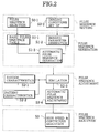
- Fig. 2 is a functional flow chart for one embodiment of the method for pulse sequence control according to the present invention to be carried out by the apparatus of Fig. 1.
- Figs. 3A and 3B are illustration of a parameter block to be used in the pulse sequence generation section in the flow chart of Fig. 2.
- Fig. 4 is a block diagram of a gradient coil power source in the apparatus of Fig. 1 for explaining the exemplary change of the parameters in the parameter block of Figs. 3A and 3B.
- Fig. 5 is a schematic block diagram of an RF pulse generating system in the apparatus of Fig. 1.
- Fig. 6 is a schematic block diagram of a gradient magnetic field generating system in the apparatus of Fig. 1.
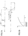
- Figs. 7A and 7B are a pulse sequence timing chart and a graph for explaining a manner of determining the transient response.
- Figs. 8A and 8B are pulse sequence timing charts for explaining a manner of measuring a magnetic field distribution.
- Fig. 9 is a schematic block diagram of an eddy current compensation unit in the gradient magnetic field generating system of Fig. 6.
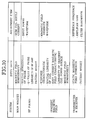
- Fig. 10 is a table summarizing exemplary pulse sequence adjustment according to the pulse sequence adjustment section in the flow chart of Fig. 2.
- Fig. 11 is a block diagram of a sequence controller in the apparatus of Fig. 1.
- Fig. 12 is a block diagram of an event control unit in the sequence controller of Fig. 9.
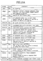
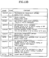
- Figs. 13A and 13B are tables summarizing the operation codes to be used in an event memory in the event control unit of Fig. 12.
- Fig. 14 is an illustration of a fully developed data structure of the event table used in the event control unit of Fig. 12.
- Fig. 15 is an illustration of a data structure in the event memory in the event control unit of Fig. 12.
- Fig. 16 is an illustration of a data structure of a rewriting table used in the event control unit of Fig. 12.
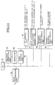
- Fig. 17 is a flow chart for the procedure of rewriting the event memory in the event control unit of Fig. 12.
- a nuclear magnetic resonance imaging apparatus for realizing one embodiment of a method for pulse sequence control in a nuclear magnetic resonance imaging according to the present invention will be described in detail.
- the apparatus comprises: a main magnet 1 for generating a static magnetic field; a main magnet power source 2 for driving the main magnet 1; gradient coils 3 for generating appropriate reading, slicing, and phase encoding gradient magnetic fields Gr, Gs, and Ge; a gradient coil power source 4 for driving the gradient coils 3; a probe 6 for applying radio frequency (RF) pulses to the patient 5 and receiving nuclear magnetic resonance (NMR) signals from the patient 5; a transmitter unit 7 for driving the probe 6 to transmit the desired RF pulses; a receiver unit 8 for detecting the NMR signals received by the probe 6; a data acquisition unit 10 for collecting and A/D converting the NMR signals detected by the receiver unit 8; a data processing unit 11 for data processing the A/D converted NMR signals to reconstruct the desired NMR image; a system controller 9 for controlling the operations of the main magnet power source 2, the gradient coil power source 4, the transmitter unit 7, the receiver unit 8, the data acquisition unit 10, and the data processing unit 11; a display unit 14 for a display unit 14 for generating
- the patient 5 is placed inside the static magnetic field generated by the main magnet 1, and three orthogonal gradient magnetic fields generated by the gradient coils 3 are superposed onto the static magnetic field while the RF pulses are applied by the probe 6, according to the desired imaging pulse sequence realized by the controlling of the sequence controller 9. Then, the NMR signals emitted from the patient 5 in response to the application of the RF pulses are received by the probe 6, according to which the data processing unit 11 reconstructs the desired NMR images by using appropriate data processing operations such as the Fourier transformation.
- a desired pulse sequence type is selected at the step S0-1 and desired imaging conditions such as imaging region, imaging direction, etc. are specified at the step S0-2, by the operator through the console 13.
- the basic pulse sequence form for the desired pulse sequence type selected at the step S0-1 is read out from a basic pulse sequence table at the step S1-1, while the imaging parameters corresponding to the desired imaging conditions specified at the step S0-2 are generated at the step S1-1, at the host computer 12.
- the host computer 12 automatically generates the appropriate pulse sequence at the step S1-3 and transmits the generated pulse sequence to the system controller 9, in a manner described in detail below.
- the sequence controller 9 carries out the simulation of the pulse sequence execution by using the simulated RF pulse waveform, the simulated gradient magnetic field waveform, the simulated static magnetic field, and the simulated nuclear spin density distribution at the step S2-3 according to the pulse sequence generated at the step S1-3, the system characteristics measured at the step S3-1, and the patient characteristics measured at the step S3-2. Then, the sequence controller 9 automatically adjusts the pulse sequence appropriately at the step S2-4 according to the result of the simulation obtained at the step S2-3, in a manner described in detail below.
- the high speed and continuous pulse sequence execution is realized at the step S3 by the system controller 9, by speeding up the operations related to the decoding of the event codes and the rewriting of the event memory, in a manner described in detail below.
- each of the host computer 12 and the sequence controller 9 is equipped with a parameter block having a data structure as shown in Figs. 3A and 3B.
- This parameter block specifies the imaging parameters corresponding to the desired imaging conditions specified by the operator, such as the time parameters including the repetition time TR and the echo time TE, the imaging region size, and other parameters related to the imaging conditions.
- the host computer 12 is also equipped with the basic pulse sequence table containing the definition of the basic form of the pulse sequence for each pulse sequence type.
- the host computer 12 automatically generates the appropriate pulse sequence by using the parameter block and the basic pulse sequence table, and transmits the generated pulse sequence to the sequence controller 9 in a form of an event table to be stored in the event memory in the sequence controller 9 which will be described in detail below.
- the host computer 12 also generates a rewriting table to be described in detail below along with the event table.
- the imaging parameters of the pulse sequence affected by the imaging conditions are collectively managed by the parameter block, while the basic forms of the pulse sequence for different pulse sequence types which are unaffected by the imaging conditions are collectively managed by the basic pulse sequence table, and the actual pulse sequence can be generated automatically by the host computer 12 by using the parameter block and the basic pulse sequence table, so that the change of the pulse sequence can be achieved at high speed by simply specifying the imaging parameters to be changed in the parameter block alone.
- the imaging conditions set up by the operator through the console 13 can be reflected immediately in the next image, so that it becomes possible to realize the real time interactive pulse sequence set up procedure.
- the imaging parameters in the parameter block can be changed in the following manners, for example.
- the pulse sequence adjustment is carried out in three steps including a characteristic parameter measurement step, a simulation step, and an adjustment step.
- the characteristic parameters affecting the execution of the pulse sequence in the following two categories are measured.
- the RF power condition must be specified for every pulse sequence, and in particular, it is necessary to specify the RF power accurately for the IR pulses.
- the static magnetic field distribution can be measured accurately, as shown in Figs. 8A and 8B, by taking two sets of the images (using the spin echo scheme or the double echo scheme) using slightly different echo times TE and TE + ⁇ T, and by estimating the static magnetic field distribution according to the difference between the phases ⁇ 0 ⁇ and ⁇ 1 for these two sets of the images.
- the static magnetic field distribution so determined can then be utilized in adjusting the shim coil current strength, so as to improve the homogeneity of the static magnetic field.
- This adjustment of the static magnetic field is particularly important for the high speed imaging method such as EPI which can easily be affected by the inhomogeneity of the static magnetic field.
- the simulation of the pulse sequence execution using the simulated RF pulse waveform, the simulated gradient magnetic field waveforms, the simulated static magnetic field, and the simulated nuclear spin density distribution is carried out according to the system and patient characteristic parameters obtained by the characteristic parameter measurement step described above, as follows.
- the spin motion due to the application of the RF pulses can be calculated from the following Bloch equation (1).
- dM/dt ⁇ M ⁇ B - (iM x + jM y )/T2 + k(M 0 ⁇ - M z )/T1 (1)
- M is a magnetic moment of the spin
- ⁇ is the gyromagnetic ratio of the spin
- T1 is a longitudinal relaxation time
- T2 is a transverse relaxation time
- i, j, and k are unit vector in X, Y and Z directions
- the magnetic field B is given by the following two equations (2) and (3).
- B kB 0 ⁇ ' + B1 (2)
- B 0 ⁇ ' B 0 ⁇ + ⁇ B + G ⁇ r (3)
- B 0 ⁇ is the static magnetic field
- B1 is an input waveform of the RF pulses
- ⁇ B is an inhomogeneity of the static magnetic field
- G is the gradient magnetic field strength
- r is a radial position.
- the magnetic moment M' of the spin at each time t can be calculated by using the simulated RF pulse waveform, the simulated gradient magnetic field waveforms, and the simulated static magnetic field. Consequently, the slice characteristics and the signal strength at the time of the application of the RF pulses can be calculated.
- the echo signal S(t) can be expressed by the following equation (4).
- S(t) ⁇ ⁇ (x, y) ⁇ exp[-2 ⁇ j ⁇ G x (x, y, t)x + G y (x, y, t) + ⁇ B(x, y) t ⁇ ]dxdy (4)
- ⁇ is the simulated nuclear spin density distribution
- G x and G y are the integrated waveforms of the gradient magnetic field strengths in X and Y directions given by the following equations (5) and (6).
- G x (x, y, t) ⁇ g x (x, y, t) dt (5)
- G y (x, y, t) ⁇ g y (x, y, t) dt (6)
- g x and g y are the gradient magnetic field waveforms in the X and Y directions.
- the echo signal S(t) can be calculated from the simulated gradient magnetic field waveforms g x and g y , the simulated static magnetic field, and the simulated nuclear spin density distribution.
- the simulated RF pulse waveform, the simulated gradient magnetic field waveforms, the simulated static magnetic field, and the simulated nuclear spin density distribution should be obtained by the sufficiently high performance computer device such that the simulation can be made in a relatively short period of time compared with the actual image taking time.
- the adjustment of the pulse sequence according to the result of the simulation obtained at the simulation step described above is made as follows.
- the factor concerning the homogeneity of the static magnetic field can be dropped in the above described calculation of the spin motion according to the Bloch equation.
- the slice characteristic can be determined accurately.
- the spin motion and the slice characteristic can be calculated from the standard image for each imaging portion, the characteristics of each probe, and the simulated gradient magnetic field waveforms, so that they can be determined and stored in a form of a database.
- the non-linearity of the amplitude level can be easily realized by multiplying the linearizing function for each probe with the selective excitation pulse waveform.
- the finer adjustment of the slice characteristic can be achieved by using the magnetic fields after the magnetic field adjustment in the Bloch equation.
- the realizable level of the adjustment depends on the performance level of the sequence controller 9. Namely, for the RF pulses, it is easy to control the output amplitude so as to compensate the non-linearity of the amplitude level, but the adjustment of the frequency characteristic and the phase characteristic which are required in the finer adjustment can be realized only when the high level sequence controller is used.
- the high precision measurement of the magnetic field distribution can be made.
- the echo signal S(t) can be calculated by the equation (4) by using the density ⁇ of a prescribed virtual phantom, along with the integrated waveforms G x and G y of the gradient magnetic field strengths in X and Y directions obtained from the transmission characterstics of the gradient magnetic fields accounting for the influence of the eddy currents under the condition of keeping the magnetic field homogeneity below a prescribed value.
- the gradient magnetic field waveforms are adjusted such that the norm of the echo signal S(t) in the k-space has the maximum value at the origin of the k-space.
- the echo signal S(t) is calculated again by the equation (4) by using the influence of the residual magnetic field distribution after the magnetic field homogeneity adjustment. In this manner, the inhomogeneity of the gradient magnetic fields can be removed up to the first order components.
- the eddy current compensation unit 48 having a configuration as shown in Fig. 9 can be utilized.
- the input rectangular waveform is modulated by adding the exponentially decaying waveforms generated by a plurality of RC circuit 61 having different time constants, so as to obtain the control waveform with the improved rising time.
- the positioning of the signal peak can be made by sequentially changing the amplitude level and the timing of the rectangular input waveform until the integrated value of the echo signal S(t) falls within the appropriate range.
- the pulse sequence becomes quite lengthy, so that the adjustment as described above is particularly effective.
- the gain of the gradient field amplifier is to be reduced gradually.
- the number of pre-scannings for the pulse sequence adjustment can be minimized, so that the required image taking time as a whole can be shortened, while reducing an amount of RF pulses and the gradient magnetic fields to be applied onto the patient.
- the standard pulse sequences prepared at the manufacturer's factory can easily be adapted optimally to the individual site of the practical use, by utilizing the automatic pulse sequence adjustment as described above.
- the sequence controller 9 comprises: a CPU 21 for controlling the operation of the sequence controller 9 as a whole; a data transmission unit 22 for transmitting data with respect to the host computer 12; a sequence generation unit 23 used in the pulse sequence generation section described above; a simulator 24 used in the pulse sequence adjustment section described above; an event control unit 25 having a plurality of event memories for storing the event tables in terms of the event codes; an RF control unit 26 for controlling the transmitter unit 7 and the receiver unit 8; a data acquisition and processing control unit 27 for controlling the data acquisition unit 10 and the data processing unit 11; a gradient magnetic field control unit 28 for controlling the gradient field power source 4; and a static magnetic field control unit 29 for controlling the main magnet power source 2.
- the RF control unit 26, the data acquisition control unit 27, the gradient magnetic field control unit 28, and the static magnetic field control unit 29 are controlled by the event control unit 25 according to the event table stored in the event memories provided in correspondence to each of these units.
- the event control unit 25 when at least one of the event memories is used in controlling one of these units, the remaining ones of the event memories are accessible for rewriting, and the high speed and continuous execution of the pulse sequence is realized by sequentially switching the currently used event memory.
- This event control unit 25 has a further detail configuration as shown in Fig. 12, which is incorporating a feature to improve the time resolution of the event controlling.
- the event control unit 25 comprises: a plurality of event memories 31, which store the event table; a timer 32 for counting time, which is operated by the clock signal CLK; the comparator 33 for comparing the time counted by the timer 32 with each time registered in each entry in each event memory 31; an AND gate 37 for taking AND of the clock signal CLK and the output of the comparator 33; an address counter for counting the address in the event memory 31; a plurality (N in this embodiment) of decoders (D N-1 to D 0 ⁇ ) 37 connected in series, for decoding the event memory entries read out from the currently used event memory 31 according to the addresses specified by the address counter 35; a first switch 38 for selectively supplying the time registered in each entry in the event memories 31 to the comparator 33, according to the output of the decoders 37; and a second switch 39 for selectively supplying each entry read out from the currently used event memory 31 to the decoders 37, according to the output of the decoders 37.
- each entry of each event memory 31 has the slots for Time, Operation code (OP), Argument (Arg), and flags (flg) , as will be described in detail below.
- the event decoding operation is divided into a plurality of steps by using the decoders 37 connected in series, and each step of decoding is carried out at each clock CLK, in order to speed up the event decoding speed.
- the decoded data are sequentially handed from one of the decoders 37 to the next one of the decoders 37, such that the pre-reading of a plurality of the event codes can be realized in a manner similar to the pre-reading control used in a computer technology.
- the decoders 37 effectively decodes a plurality of the event codes in parallel, and the event control unit 25 is capable of carrying out a plurality of the mutually consistent events simultaneously.
- this event control unit 25 it becomes possible in this event control unit 25 to improve the time resolution of the event controlling, because of the pre-reading realized by the decoders 37 and a plurality of the event memories 31 which can be selectively connected to the decoders 37.
- SEP memory is a spin excitation pulse memory for storing the RF pulse forms.
- an event table for specifying an entire pulse sequence execution according to the operation codes as shown in Figs. 13A and 13B can have a plurality of arguments, so that the event table itself has a fully developed data structure as shown in Fig. 14, where the meaning of each slot is as follows.
- the frequency and the increment for the rewriting of each of the time, the operation code, and the arguments are specified, so as to facilitate the repeated executions of the same pulse sequences with sequentially changed imaging conditions according to which the event table must be rewritten.
- each event memory 31 stores a part of the event table in a form shown in Fig. 15 including the slots for Time, OP-code, and Arg similar to those shown in Fig. 14, along with the flags Time-flg, OP-flg, and Arg-flg, where the meaning of each flag is as follows.
- the rewriting table in a form shown in Fig. 16 is also provided in the event control unit 25, where the meaning of each slot is as follows.
- the appropriate rewriting table entry specifying a manner of rewriting each one of the time slot, operation code slot, and the argument slot can be indicated by the flags, so that the appropriate rewriting can be carried out in accordance with the indicated rewriting table entry, only for the slot that needs to be rewritten.
- the event memory rewriting operation can be made faster in this embodiment.
- the fields for the flags may not necessarily be provided in the event memory integrally, and the similar effect can also be obtained by providing the similar flags on the host computer 12 side.
- the rewriting operation using these event memory and the rewriting table can be carried out for a case of rewriting the argument portion, for example, according to the flow chart of Fig. 17 as follows.
- the process proceeds to the step ST9 described below, whereas otherwise next at the step ST4, the rewriting mode is selected according to the Mode registered in the selected rewriting table entry.
- the increment specified by the event memory is added to the current value at the step ST5, and registered as an i-th entry at the step ST6.
- the reversal mode R next at the step ST7, the bit value of the current value is reversed.
- the table look-up mode next at the step ST8, the event table is looked up.
- the counter number i is increased by one, and next at the step ST 10, whether the increased counter number i is not greater than the event step numbers, When it is so, the process returns to the step ST1 above, whereas otherwise the process is terminated.
- the unnecessary top portions can be skipped at each TR by starting the event execution function from the appropriate address.
- the operation of the event control unit can be stopped and the control can be returned back to the host computer 12 side, or else the OP-code is rewritten to NOP.
- the starting address setting and the STOP command can be carried out, with a plurality of the starting addresses specified in the event memory, so that the event memory can be divided over a plurality of banks, and the re-loading of the event memory can be eliminated.
- the pulse sequence execution according to this embodiment proceeds in the following steps for a case of the pin echo (SE) and for a case of the high speed imaging method.
- steps (a) to (e) are sequentially carried out according to the predetermined schedule, and a plurality of images can be obtained by repeating the steps (d) and (e).
- the TR interval itself can be managed by the real time timer of the host computer 12.
- the steps (a) to (e) similar to those described above for the case of SE are carried out.
- the execution of the event memory and the rewriting of the event memory can be carried out in parallel in such a manner that while one event memory is executed, the other event memories are rewritten.
- the TR interval itself can be managed by a waiting time up to the channel switching instruction provided at the end of each event memory.
Landscapes
- Physics & Mathematics (AREA)
- Engineering & Computer Science (AREA)
- Signal Processing (AREA)
- High Energy & Nuclear Physics (AREA)
- Condensed Matter Physics & Semiconductors (AREA)
- General Physics & Mathematics (AREA)
- Health & Medical Sciences (AREA)
- General Health & Medical Sciences (AREA)
- Nuclear Medicine, Radiotherapy & Molecular Imaging (AREA)
- Radiology & Medical Imaging (AREA)
- Magnetic Resonance Imaging Apparatus (AREA)
Applications Claiming Priority (2)
| Application Number | Priority Date | Filing Date | Title |
|---|---|---|---|
| JP07792592A JP3396490B2 (ja) | 1992-03-31 | 1992-03-31 | 磁気共鳴映像装置 |
| JP77925/92 | 1992-03-31 |
Publications (2)
| Publication Number | Publication Date |
|---|---|
| EP0567794A2 true EP0567794A2 (de) | 1993-11-03 |
| EP0567794A3 EP0567794A3 (en) | 1993-12-22 |
Family
ID=13647671
Family Applications (1)
| Application Number | Title | Priority Date | Filing Date |
|---|---|---|---|
| EP19930105339 Ceased EP0567794A3 (en) | 1992-03-31 | 1993-03-31 | Nuclear magnetic resonance imaging with high speed and interactive pulse sequence control |
Country Status (3)
| Country | Link |
|---|---|
| US (1) | US5519320A (de) |
| EP (1) | EP0567794A3 (de) |
| JP (1) | JP3396490B2 (de) |
Cited By (8)
| Publication number | Priority date | Publication date | Assignee | Title |
|---|---|---|---|---|
| WO1995034242A1 (en) * | 1994-06-14 | 1995-12-21 | Philips Electronics N.V. | Magnetic resonance imaging method with pulse sequence optimisation and device for such method |
| US5758646A (en) * | 1994-09-12 | 1998-06-02 | U.S. Philips Corporation | Magnetic resonance imaging method with pulse sequence optimization and device for such method |
| EP1004891A3 (de) * | 1998-11-25 | 2000-07-05 | General Electric Company | System zur Bilderzeugung durch magnetische Resonanz mit interaktiver Kontrolle des Bildkontrastes |
| NL1013496C2 (nl) * | 1998-11-05 | 2000-07-06 | Schlumberger Holdings | NMR gereedschap met een programmeerbare pulsvolgordegenerator voor onder in het boorgat. |
| WO2003021284A1 (en) | 2001-08-28 | 2003-03-13 | Koninklijke Philips Electronics Nv | System and method of user guidance in magnetic resonance imaging including operating curve feedback and multi-dimensional parameter optimization |
| WO2005101049A1 (en) | 2004-04-08 | 2005-10-27 | Varian, Inc. | Optimized channel controller for nmr apparatus |
| DE102007036564A1 (de) * | 2007-08-03 | 2009-02-19 | Siemens Ag | Verfahren zur Optimierung von Bildgebungsparametern |
| DE102008032007A1 (de) * | 2008-07-07 | 2010-02-04 | Siemens Aktiengesellschaft | Verfahren und System zur Simulation eines MR-Bildes |
Families Citing this family (34)
| Publication number | Priority date | Publication date | Assignee | Title |
|---|---|---|---|---|
| US5898305A (en) * | 1993-11-26 | 1999-04-27 | Kabushiki Kaisha Toshiba | Magnetic resonance imaging apparatus having a fluoroscopy mode |
| US6636038B1 (en) | 1997-05-28 | 2003-10-21 | Siemens Aktiengesellschaft | Method and apparatus for controlling a pulse sequence in a magnetic resonance tomography system |
| US6025717A (en) * | 1997-06-23 | 2000-02-15 | Fonar Corporation | Diagnostic simulator for MRI |
| JP3732365B2 (ja) * | 1999-09-08 | 2006-01-05 | ジーイー横河メディカルシステム株式会社 | スピン励起方法および装置並びに磁気共鳴撮像装置 |
| JP4632535B2 (ja) | 2000-12-27 | 2011-02-16 | 株式会社東芝 | Mri装置 |
| US6801800B2 (en) * | 1999-11-29 | 2004-10-05 | Kabushiki Kaisha Toshiba | MR imaging using ECG-prep scan |
| JP4350855B2 (ja) * | 1999-12-01 | 2009-10-21 | 株式会社日立メディコ | 磁気共鳴イメージング装置 |
| WO2001084173A2 (en) * | 2000-04-26 | 2001-11-08 | Mayo Foundation For Medical Education And Research | Reduction of motion artifact in nmr images using spherical navigator signals |
| US6690961B1 (en) | 2000-05-12 | 2004-02-10 | Toshiba America Mri, Inc. | Apparatus and method for transition between fluoro-mode and diagnostic mode magnetic resonance imaging |
| US6711511B2 (en) * | 2000-07-06 | 2004-03-23 | Fujitsu Limited | Electromagnetic wave analyzing apparatus and computer readable storage medium |
| DE10055417C2 (de) * | 2000-11-09 | 2002-10-24 | Siemens Ag | Verfahren zum Erzeugen von Magnetresonanzbildern mit optimaler Einstellung von Sequenzparametern |
| US6566877B1 (en) * | 2000-12-26 | 2003-05-20 | Koninklijke Philips Electronics, N.V. | Band-limited gradient waveforms |
| JP5002099B2 (ja) | 2001-08-31 | 2012-08-15 | 株式会社東芝 | 磁気共鳴イメージング装置 |
| US6833702B1 (en) * | 2001-09-07 | 2004-12-21 | Fonar Corporation | System, method and methodology for reconfigurability of magnetic resonance imagers |
| DE10150138B4 (de) * | 2001-10-11 | 2009-10-08 | Siemens Ag | Verfahren zur Magnetresonanz-Bildgebung |
| US6933720B2 (en) | 2001-12-11 | 2005-08-23 | Toshiba America Mri, Inc. | Sequence preconditioning for ultra-fast magnetic resonance imaging |
| JP3907182B2 (ja) * | 2002-05-07 | 2007-04-18 | 株式会社東芝 | 磁気共鳴映像装置 |
| US6822446B2 (en) * | 2002-09-12 | 2004-11-23 | Ge Medical Systems Global Technology Company, Llc | MRI magnet vibration induced field instability simulator |
| DE10346410A1 (de) * | 2003-10-07 | 2005-05-04 | Martin Tank | Verfahren zur Bestimmung von patientenbezogenen Informationen zur Position und Orientierung von Schnittbildaufnahmen bei magnetresonanztomographischen Untersuchungen |
| DE102007013422B4 (de) * | 2007-03-20 | 2010-05-06 | Siemens Ag | Verfahren zur Steuerung eines Magnetresonanzsystems und Magnetresonanzsystem |
| JP5675057B2 (ja) * | 2008-07-01 | 2015-02-25 | 株式会社東芝 | 磁気共鳴イメージング装置および受信経路切り替え方法 |
| DE102008044827B3 (de) * | 2008-08-28 | 2010-04-08 | Siemens Aktiengesellschaft | Verfahren und Vorrichtung zum Erzeugen einer zeitrasterangepassten Messsequenz für einen Magnetresonanz-Scanner, die auf einem Zeitraster des Magnetresonanz-Scanners ausführbar ist |
| DE102008044828B3 (de) * | 2008-08-28 | 2010-04-15 | Siemens Aktiengesellschaft | Verwendung eines Magnetresonanz-Sequenzmodells zur formalen Beschreibung einer Messsequenz |
| US20110200243A1 (en) * | 2008-10-20 | 2011-08-18 | Hitachi Medical Corporation | Magnetic resonance imaging apparatus and method |
| DE102009057582B4 (de) * | 2009-12-09 | 2012-07-26 | Siemens Aktiengesellschaft | Verfahren zum Aufbau von zumindest einem Teilbereich einer Pulssequenz einer Magnetresonanzvorrichtung und entsprechende Pulssequenz |
| JP4991908B2 (ja) * | 2010-05-17 | 2012-08-08 | 株式会社東芝 | 磁気共鳴イメージング装置および磁気共鳴イメージング方法 |
| CN102905617A (zh) * | 2010-05-28 | 2013-01-30 | 株式会社日立医疗器械 | 磁共振成像装置及高频磁场脉冲的调制方法 |
| JP5780512B2 (ja) * | 2010-06-07 | 2015-09-16 | 株式会社東芝 | 磁気共鳴イメージング装置 |
| JP5159836B2 (ja) * | 2010-07-16 | 2013-03-13 | 株式会社東芝 | Mri装置 |
| JP6045797B2 (ja) * | 2011-04-06 | 2016-12-14 | 東芝メディカルシステムズ株式会社 | 磁気共鳴イメージング装置 |
| KR101767213B1 (ko) * | 2011-09-15 | 2017-08-11 | 삼성전자주식회사 | Mri 시스템의 rf 코일을 제어하는 방법 및 이를 위한 장치 |
| US9146293B2 (en) * | 2012-02-27 | 2015-09-29 | Ohio State Innovation Foundation | Methods and apparatus for accurate characterization of signal coil receiver sensitivity in magnetic resonance imaging (MRI) |
| JP5380585B2 (ja) * | 2012-07-05 | 2014-01-08 | 株式会社東芝 | Mri装置 |
| DE102014211586B3 (de) * | 2014-06-17 | 2015-10-22 | Siemens Aktiengesellschaft | Verwendung von Abhängigkeitsdatensätzen bei der Bereitstellung und/oder Überprüfung von MR-Messsequenzen |
Family Cites Families (7)
| Publication number | Priority date | Publication date | Assignee | Title |
|---|---|---|---|---|
| US5068786A (en) * | 1984-11-08 | 1991-11-26 | Elscint Ltd. | Method for controlling radio frequency excitation and gradient pulse characteristics in a magnetic resonance imaging system |
| US4707797A (en) * | 1985-03-20 | 1987-11-17 | Advanced Nmr Systems, Inc. | Function generator for NMR system |
| US4835690A (en) * | 1985-11-19 | 1989-05-30 | Picker International, Inc. | Integrated expert system for medical imaging scan, set-up, and scheduling |
| DE3920997C1 (de) * | 1989-06-27 | 1990-08-23 | Bruker Analytische Messtechnik Gmbh, 7512 Rheinstetten, De | |
| JPH0337044A (ja) * | 1989-07-05 | 1991-02-18 | Hitachi Ltd | Mriシーケンス設計支援方法 |
| US5144242A (en) * | 1990-08-23 | 1992-09-01 | The Regents Of The University Of California | Continually loadable microcode store for MRI control sequencers |
| US5309102A (en) * | 1993-05-07 | 1994-05-03 | General Electric Company | Frequency calibration for MRI scanner |
-
1992
- 1992-03-31 JP JP07792592A patent/JP3396490B2/ja not_active Expired - Fee Related
-
1993
- 1993-03-31 US US08/040,857 patent/US5519320A/en not_active Expired - Lifetime
- 1993-03-31 EP EP19930105339 patent/EP0567794A3/en not_active Ceased
Cited By (16)
| Publication number | Priority date | Publication date | Assignee | Title |
|---|---|---|---|---|
| WO1995034242A1 (en) * | 1994-06-14 | 1995-12-21 | Philips Electronics N.V. | Magnetic resonance imaging method with pulse sequence optimisation and device for such method |
| US5758646A (en) * | 1994-09-12 | 1998-06-02 | U.S. Philips Corporation | Magnetic resonance imaging method with pulse sequence optimization and device for such method |
| NL1013496C2 (nl) * | 1998-11-05 | 2000-07-06 | Schlumberger Holdings | NMR gereedschap met een programmeerbare pulsvolgordegenerator voor onder in het boorgat. |
| US6400147B1 (en) | 1998-11-05 | 2002-06-04 | Schlumberger Technology Corporation | Downhole NMR tool having a programmable pulse sequencer |
| EP1004891A3 (de) * | 1998-11-25 | 2000-07-05 | General Electric Company | System zur Bilderzeugung durch magnetische Resonanz mit interaktiver Kontrolle des Bildkontrastes |
| US6166544A (en) * | 1998-11-25 | 2000-12-26 | General Electric Company | MR imaging system with interactive image contrast control |
| US6362620B1 (en) | 1998-11-25 | 2002-03-26 | Ge Medical Systems Global Technology Company, Llc | MR imaging system with interactive image contrast control over a network |
| US6377046B1 (en) | 1998-11-25 | 2002-04-23 | Ge Medical Systems Global Technology Company, Llc | System and method for interactive image contrast control in a magnetic resonance imaging system |
| WO2003021284A1 (en) | 2001-08-28 | 2003-03-13 | Koninklijke Philips Electronics Nv | System and method of user guidance in magnetic resonance imaging including operating curve feedback and multi-dimensional parameter optimization |
| US6687527B1 (en) | 2001-08-28 | 2004-02-03 | Koninklijke Philips Electronics, N.V. | System and method of user guidance in magnetic resonance imaging including operating curve feedback and multi-dimensional parameter optimization |
| WO2005101049A1 (en) | 2004-04-08 | 2005-10-27 | Varian, Inc. | Optimized channel controller for nmr apparatus |
| US7053614B2 (en) | 2004-04-08 | 2006-05-30 | Varian, Inc. | Optimized channel controller for NMR apparatus |
| DE102007036564A1 (de) * | 2007-08-03 | 2009-02-19 | Siemens Ag | Verfahren zur Optimierung von Bildgebungsparametern |
| DE102007036564B4 (de) * | 2007-08-03 | 2009-07-09 | Siemens Ag | Verfahren zur gewebespezifischen Optimierung von Bildgebungsparametern |
| US7821266B2 (en) | 2007-08-03 | 2010-10-26 | Siemens Aktiengesellschaft | Method and device for optimization of imaging parameters |
| DE102008032007A1 (de) * | 2008-07-07 | 2010-02-04 | Siemens Aktiengesellschaft | Verfahren und System zur Simulation eines MR-Bildes |
Also Published As
| Publication number | Publication date |
|---|---|
| JP3396490B2 (ja) | 2003-04-14 |
| US5519320A (en) | 1996-05-21 |
| EP0567794A3 (en) | 1993-12-22 |
| JPH05277085A (ja) | 1993-10-26 |
Similar Documents
| Publication | Publication Date | Title |
|---|---|---|
| US5519320A (en) | Nuclear magnetic resonance imaging with high speed and interactive pulse sequence control | |
| EP0188006B1 (de) | Verfahren zur Umkehrung der transversalen Restmagnetisierung durch Anwendung von phasenkodierenden Magnetfeldgradienten,und Apparat | |
| EP0634664B1 (de) | Vorabtastung mit einer schnellen Spinecho-Sequenz für ein Abbildgerät mit magnetischer Resonanz | |
| US5168226A (en) | Acquisition of multiple images in fast spin echo nmr scans | |
| US5229717A (en) | Simultaneous two-contrast fast spin echo NMR imaging | |
| US4950994A (en) | Gradient and polarizing field compensation | |
| EP0228056A2 (de) | Verfahren zum Ausgleich des Wirbelstromes eines Gradientenmagnetfeldes | |
| US5212448A (en) | Nmr pulse sequence with burst rf excitation pulses having separately controlled phase | |
| US5704357A (en) | Method of producing MR image and MRI system | |
| US5345176A (en) | Stabilized fast spin echo NMR pulse sequence with improved slice selection | |
| EP1004893B1 (de) | Ein Verfahren zur Kompensierung der remanenten Magnetisierung in ferromagnetischem Material eines MRI-Systems | |
| GB2089996A (en) | Nuclear magnetic resonance imaging | |
| US5237273A (en) | Interleaved acquisition of multi-slice NMR data | |
| EP0132336A2 (de) | Verfahren und Vorrichtung zur Steigerung von T1-NMR-Messungen bei Anwendung von miteinander verknüpften Repetitionsintervallen durch ganzzahlige Faktoren | |
| US6933720B2 (en) | Sequence preconditioning for ultra-fast magnetic resonance imaging | |
| US4631480A (en) | Nuclear magnetic resonance method and apparatus | |
| JPH0418856B2 (de) | ||
| US20020050816A1 (en) | MR imaging method, phase error measuring method, and MRI apparatus | |
| US5227726A (en) | Nuclear magnetic resonance methods and apparatus | |
| JP2528864B2 (ja) | 核磁気共鳴を用いた検査装置 | |
| US5051697A (en) | Flow angiology with static signal suppression | |
| JPH11225995A (ja) | 磁気共鳴イメージング装置 | |
| JP3510901B2 (ja) | 磁気共鳴イメージング装置 | |
| JPH04343833A (ja) | 静磁場不均一の一次項補正の可能な磁気共鳴イメージン グ装置 | |
| JPH04224735A (ja) | 磁気共鳴イメージング装置用高周波変調器 |
Legal Events
| Date | Code | Title | Description |
|---|---|---|---|
| PUAI | Public reference made under article 153(3) epc to a published international application that has entered the european phase |
Free format text: ORIGINAL CODE: 0009012 |
|
| 17P | Request for examination filed |
Effective date: 19930331 |
|
| AK | Designated contracting states |
Kind code of ref document: A2 Designated state(s): DE FR GB |
|
| PUAL | Search report despatched |
Free format text: ORIGINAL CODE: 0009013 |
|
| AK | Designated contracting states |
Kind code of ref document: A3 Designated state(s): DE FR GB |
|
| 17Q | First examination report despatched |
Effective date: 19960222 |
|
| APBN | Date of receipt of notice of appeal recorded |
Free format text: ORIGINAL CODE: EPIDOSNNOA2E |
|
| APBR | Date of receipt of statement of grounds of appeal recorded |
Free format text: ORIGINAL CODE: EPIDOSNNOA3E |
|
| APAF | Appeal reference modified |
Free format text: ORIGINAL CODE: EPIDOSCREFNE |
|
| APBT | Appeal procedure closed |
Free format text: ORIGINAL CODE: EPIDOSNNOA9E |
|
| 18R | Application refused |
Effective date: 20060721 |