EP0568105A1 - Capteur de vitesse angulaire d'un interferomètre optique avec autodiagnostique - Google Patents
Capteur de vitesse angulaire d'un interferomètre optique avec autodiagnostique Download PDFInfo
- Publication number
- EP0568105A1 EP0568105A1 EP93107088A EP93107088A EP0568105A1 EP 0568105 A1 EP0568105 A1 EP 0568105A1 EP 93107088 A EP93107088 A EP 93107088A EP 93107088 A EP93107088 A EP 93107088A EP 0568105 A1 EP0568105 A1 EP 0568105A1
- Authority
- EP
- European Patent Office
- Prior art keywords
- signal
- output
- diagnosis
- reference signal
- self
- Prior art date
- Legal status (The legal status is an assumption and is not a legal conclusion. Google has not performed a legal analysis and makes no representation as to the accuracy of the status listed.)
- Granted
Links
Images




Classifications
-
- G—PHYSICS
- G01—MEASURING; TESTING
- G01C—MEASURING DISTANCES, LEVELS OR BEARINGS; SURVEYING; NAVIGATION; GYROSCOPIC INSTRUMENTS; PHOTOGRAMMETRY OR VIDEOGRAMMETRY
- G01C19/00—Gyroscopes; Turn-sensitive devices using vibrating masses; Turn-sensitive devices without moving masses; Measuring angular rate using gyroscopic effects
- G01C19/58—Turn-sensitive devices without moving masses
- G01C19/64—Gyrometers using the Sagnac effect, i.e. rotation-induced shifts between counter-rotating electromagnetic beams
- G01C19/72—Gyrometers using the Sagnac effect, i.e. rotation-induced shifts between counter-rotating electromagnetic beams with counter-rotating light beams in a passive ring, e.g. fibre laser gyrometers
Definitions
- the present invention relates to an optical interferometric angular rate meter or fiber optic gyro which measures an input angular rate by detecting that the phase difference between light beams propagating through such a looped optical path as an optical fiber coil in opposite directions varies with the input angular rate. More particularly, the invention pertains to a fiber optic gyro with a self-diagnostic capability whereby the gyro is allowed to make a self-check of a failure and indicate its occurrence to a host system or send thereto a self-checking signal when the gyro performance or function is impaired or degraded.
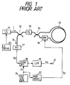
- Light I from a light source 11 passes through an optical coupler 12, a polarizer 13 and an optical coupler 14 and then enters into an optical fiber coil 15 from its opposite ends, which coil is used as an optical path.
- a tight source driver 23 is a circuit that drives the light source 11, and it is composed of, for instance, a circuit which merely supplies current to the light source 11 and a circuit which monitors a portion of the quantity of light from the light source 11 by means of a photodetector and automatically controls the light source 11 to emit a fixed quantity of light at all times.
- a reference signal generator 22 applies a modulation signal Sp via a modulator driver 22 to a phase modulator 16.
- the clockwise and counterclockwise light beams which propagate through the optical fiber coil 15 are phase modulated by the phase modulator 16 inserted between one end of the optical fiber coil 15 and the optical coupler 14.
- the phase-modulated light beams are both combined by the optical coupler 14 with the light beam emitted from the other end of the optical fiber coil 15 and interfere with each other, and the interference light is provided via the polarizer 13 to the optical coupler 12, by which it is branched to a photodetector 17.
- Vp (I/2)K op K pd ⁇ 1 + cos ⁇ ( ⁇ n (-1) n J 2n (x)cos2n ⁇ p t') - sin ⁇ (2 ⁇ (-1) n J 2n+1 (x)cos(2n+1) ⁇ p t') ⁇ (1)
- phase difference ⁇ corresponding to the applied angular rate may be detected, with high sensitivity, from the output of the photodetector 17 expressed by Eq. (1), it is necessary to detect a sin ⁇ component which maximizes the gradient of the phase difference ⁇ in the neighborhood of zero.
- sin ⁇ is a coefficient of odd harmonic components of the frequency ⁇ p , and hence a desired one of these odd harmonic components needs only to be detected. This can be done by a synchronous detection with a reference signal of the same frequency as that of the desired odd harmonic component.
- the other components including a DC component as well
- Eq. (1) are all provided as the fundamental and higher harmonic components of the frequency ⁇ p .
- the output of the synchronous detector 18 is applied to a low-pass filter 19 to cut off the detector output except for the difference component (the DC component), and only the DC component is derived at a proper gain, thereafter being provided as the output of the fiber optic gyro (hereinafter referred to as an FOG output) to a terminal 21.
- a low-pass filter 19 to cut off the detector output except for the difference component (the DC component), and only the DC component is derived at a proper gain, thereafter being provided as the output of the fiber optic gyro (hereinafter referred to as an FOG output) to a terminal 21.
- the FOG output Vo is expressed by the following equation: where K A1 is a gain.
- the input angular rate ⁇ can be detected by measuring the output Vo of the low-pass filter 19.
- the input angular rate can be detected by measuring the FOG output Vo.
- the fiber optic gyro develops an abnormality and operates at reduced performance, produces no output or continues to output an abnormal voltage, it is impossible to Judge from the FOG output alone whether the gyro is normal or abnormal -- this incurs the possibility that the system using the fiber optic gyro gets into danger.
- odd harmonic components of the phase modulation signal contained in the photoelectric-converted signal from the photodetector are each extracted while changing over the reference signal of the synchronous detector by a self-diagnostic instruction and a check is made to see if the synchronously detected output is within a prescribed range, whereby the angular rate meter is allowed to make a self-diagnosis as to whether it is normal or abnormal.
- second output means is provided to derive a cos ⁇ component from the photodetector output and the output of the second output means is used as a self-diagnostic signal.
- the invention according to the second aspect is provided with first multiplier means for squaring the output from first output means which derives the sin ⁇ component from the output of the photodetector, second multiplier means for squaring the output from the second output means and adder means for adding the outputs of the first and second multiplier means, and the output of the adder means is provided as the above-mentioned self-diagnostic signal.
- first multiplier means for squaring the output from first output means which derives the sin ⁇ component from the output of the photodetector
- second multiplier means for squaring the output from the second output means and adder means for adding the outputs of the first and second multiplier means
- the output of the adder means is provided as the above-mentioned self-diagnostic signal.
- the reference signal of the synchronous detector means is switched to a reference signal 180° out of phase with the said signal by a diagnosing instruction
- the stable point of the closed loop is shifted to a position where the phase difference between the clockwise and counterclockwise light beams is 180° or its odd multiple
- the FOG output at this time is sent to a diagnosing circuit to make a check to see if its frequency (a bias frequency) is within a prescribed range, thereby judging whether the fiber optic gyro is normal or abnormal
- the order of the frequency of the reference signal of the synchronous detector is switched by a diagnosing instruction, an even multiple component the phase modulation frequency is synchronously detected and the stable point of the closed loop is shifted to a position where the phase difference between the clockwise and counterclockwise light beams is 90° or its odd multiple.
- the FOG output at this time is provided to the diagnosing circuit to make a check to see if its frequency (a bias frequency) is within a prescribed range, thereby judging whether the fiber optic gyro is normal or abnormal.
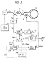
- Fig. 2 illustrates in block form an embodiment of an open loop type fiber optic gyro according to the first aspect of the present invention, in which the parts corresponding to those in Fig. 1 are identified by the same reference numerals.
- This embodiment is adapted so that the reference signal Sr, which is supplied to the synchronous detector 18, is switched, by a diagnosis instruction CTL1 from a diagnosis circuit 30, to a reference signal S r2 (hereinafter referred to as a secondary reference signal) of a frequency 2 ⁇ p twice higher than the frequency ⁇ p of the phase modulation signal Sp which is applied to the phase modulator 16.
- the reference signal generator 24 includes a clock circuit 24A which generates a signal of the frequency 2 ⁇ p , and output of the clock circuit 24A is frequency divided by a frequency divider 24B down to 1/2, providing a signal of the frequency ⁇ p .
- This signal is applied to the modulator driver 22 to produce the phase modulation signal Sp of the frequency ⁇ p .
- a switch SW1 is switched between the frequency divider 24B and the clock circuit 24A and the output of either one of them is applied as the reference signal Sr to the synchronous detector 18.
- the switch SW1 is normally connected to a terminal a, i.e. the output side of the frequency divider 24B.
- a signal S r1 (hereinafter referred to as a primary reference signal) of the same frequency ⁇ p as the phase modulation frequency ⁇ p is applied as the reference signal Sr to the synchronous detector 18.
- the output Vo at this time is expressed by Eq. (2) and is used as the output of the fiber optic gyro.
- the secondary reference signal S r2 of the frequency 2 ⁇ p twice higher than the frequency ⁇ p is applied as the reference signal Sr to the synchronous detector 18.
- the second harmonic component of the interference light is synchronously detected and provided via the low-pass filter 19 to the output terminal 21.
- a diagnosis circuit 30 makes a check to see if the secondary component output, which is a self-diagnosis signal output Vd while no angular rate input is being applied to the fiber optic gyro, is within a prescribed range, and if not, the circuit 30 outputs an alarm signal ALM.
- Fig. 3 illustrates in block form the principal part of a modified form of the embodiment depicted in Fig. 2, wherein another switch SW2 is provided.
- the reference signal generator 24 further includes an inverter 24C.
- the output of the clock circuit 24A is applied intact to a terminal a of the switch SW2 and at the same time it is also provided to a terminal b of the switch SW2 after being phase shifted by 180° by the inverter 24C.
- the switch SW2 is changed over to the output side of the inverter 24C by a second diagnosis instruction signal CTL2 from the diagnosis circuit 30. As shown in a period A in Fig.
- the state in which the switch SW1 is connected to the terminal b and the switch SW2 is connected to the terminal a is equivalent to the state in which the SW1 is connected to the terminal b in Fig. 2, and the self-diagnosis signal output Vo expressed by Eq. (2) is provided at the output terminal 21.
- the switch SW2 is changed over to the terminal b by the second diagnosis instruction signal CTL2 and the phase of the reference signal Sr is reversed, the self-diagnosis signal output Vo which is equal in magnitude to that in the above but opposite in polarity appears at the output terminal 21.
- a detected output of the angular rate that is applied to the fiber optic gyro is obtained at the terminal 21.
- the diagnosis circuit 30 makes a check to see if the polarity and absolute value of the self-diagnosis signal output of each of the two systems are within prescribed range, and it outputs the alarm signal ALM upon detection of an abnormality. Such an arrangement eliminates the possibility that output values by a failure falls within a prescribed range by chance as in the case of using one system in Fig. 2, and this enhances the reliability of the self-diagnosis feature.
- the level of the self-diagnosis signal output Vd happens to be fixed within a predetermined range of the positive polarity due to a failure of an electric circuit irrespective of the light detected output Io when the switch SW2 is held on the terminal a side, the signal Vd will not go negative even if the switch SW2 is changed over to the terminal b side, and hence the occurrence of the failure can be detected.
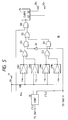
- Fig. 5 is a block diagram illustrating an example of the construction of the diagnosis circuit 30 which generates the diagnosis instruction signals CTL1 and CTL2 and makes a check to see if the self-diagnosis signal output is within a predetermined range.
- the diagnosis circuit 30 is made up of a controller 32 which outputs the diagnosis instruction signals CTL1 and CTL2 and sampling signal P SM , comparators CM1 through CM4 which compare the self-diagnosis signal output Vd with reference levels +V H , +V L , -V L and -V H , respectively, an inverter 33, gates G1 through G6 and a counter 34.
- the terminal 21 is supplied with the detected output Vo of the angular rate applied to the fiber optic gyro.
- the comparator CM1 outputs a "0" when the positive self-diagnosis signal output Vd, which is the detected output Vo while no angular rate is being applied to the fiber optic gyro, is lower than the reference voltage V H which defines the upper limit level of the normal signal output Vd.
- the comparator CM1 When the self-diagnosis signal output Vd is higher than the reference voltage V H , the comparator CM1 outputs a "1".
- the comparator CM2 outputs a "1” or "0", depending on whether the positive self-diagnosis signal output Vd is higher or lower than the reference voltage V L which defines the lower limit level of the normal signal output Vd.
- the outputs of the comparators CM1 and CM2 are provided via the OR gate G1 to the AND gate G3.
- the comparator CM3 outputs a "1" when the negative self-diagnosis signal output Vd is lower in absolute value than the reference voltage -V L (i.e. within the range from -V L to 0) which defines the lower limit level of the normal signal output Vd.
- the comparator CM3 When the signal Output Vd is higher than the reference voltage -V L on the negative side, the comparator CM3 outputs a "0".
- the comparator CM4 outputs a "0" when the negative self-diagnosis signal output Vd is lower in absolute value than the reference voltage -V H (i.e. within the range from -V H to 0) which defines the upper limit level of the normal signal output Vd.
- the comparator CM4 When the signal output Vd is higher than the reference voltage -V H on the negative side, the comparator CM4 outputs a "1".
- the outputs of the comparators CM3 and CM4 are provided via the OR gate G2 to the AND gate G
- the AND gate G3 is enabled, through which the OR of the outputs from the comparators CM1 and CM2 is provided via the OR gate G5 to the AND gate G6.
- the AND gate G4 is enabled and the OR of the outputs from the comparators CM3 and CM4 is provided via the OR gate G5 to the AND gate G6.
- the AND gate G6 is enabled when a self-diagnosis signal output sampling pulse P SM which is generated by the controller 32 and applied to the AND gate G6 goes "high" (a pulse P1) as shown in the period A in Fig. 4.
- a pulse P1 the compared outputs of the comparators CM1 and CM2 are provided to the counter 34, and as shown in the period B, the compared outputs of the comparators CM3 and CM4 are provided to the counter 34 at the timing of a pulse P2.
- the outputs of the comparators CM1 through CM4 remain “low” and the outputs Q1 and Q2 of the counter 34 both remain “low".
- the output Q1 or both of the outputs Q1 and Q2 go “high” on the basis of a "high” output signal from any one of the comparators CM1 and CM2, CM3 and CM4, and the "high” Q output is provided to a terminal 35 (351, 352), as the alarm signal ALM indicating an abnormality of the fiber optic gyro.
- the counter 34 needs to reset its outputs prior to the self-diagnosis. While the Fig. 5 embodiment has been described in the form of hardware, the above-described feature could also easily be carried out in the form of software by converting the self-diagnosis signal Vd to a digital value and loading it into a computer.
- the fundamental harmonic component of the same frequency as the phase modulation frequency ⁇ p is detected from the output of the photodetector 17, it is also possible to detect other odd harmonic components. Similarly, in the case of making a self-diagnosis, an even harmonic component may also be detected from the output of the photodetector 17 in place of the second harmonic component which is a frequency component twice higher than the phase modulation frequency ⁇ p .
- the diagnosis circuit 30, which makes a check to see if the self-diagnosis signal output Vd is within a prescribed range, is provided in the fiber optic gyro, but it may also be provided in a host system using the fiber optic gyro.
- the controller 32 for generating the diagnosis instruction signals CTL1 and CTL2 may also be provided outside of the diagnosis circuit 30.
- Fig. 6 illustrates an embodiment of the open loop fiber optic gyro according to the second aspect of the present invention, in which the parts corresponding to those in Fig. 1 are identified by the same reference numerals.
- the frequency of the reference signal Sr which is applied to the synchronous detector 18 for detecting the input angular rate is changed over to provide a selected one of the detected angular rate signal Vo and the self-diagnosis signal Vd to the output terminal 21, but in the embodiment of Fig. 6 a cos-component extractor 40 for detecting the self-diagnosis signal is provided separately of the synchronous detector for detecting the angular rate signal.
- the respective Bessel functions J n (X) in Eq. (1) undergo undulatory variations in different phases so that they are maximum at sequentially displaced or shifted positions of x.
- a desired odd harmonic component (2n+1) ⁇ p of the fundamental frequency ⁇ p which has sin ⁇ as its coefficient is detected by the synchronous detector 18 and the low-pass filter 19.
- the self-diagnosis signal is generated by a desired even harmonic component 2n ⁇ p (n ⁇ 0) in Eq. (1) which has cos ⁇ as its coefficient or a weighted combination of plural even harmonic components which have cos ⁇ as their coefficients.
- cos ⁇ components components which have cos ⁇ as their coefficients
- sin ⁇ components components which have sin ⁇ as their coefficients
- the cos-component extractor 40 is made up of a synchronous detector and a low-pass filter which extract the cos ⁇ component through use of, for example, the secondary reference signal Sr2 of the frequency 2 ⁇ p which is available from the reference signal generator 24.
- the cos-component extractor 40 may be formed so that only the second harmonic component (i.e. the 2 ⁇ p component) in Eq. (1) is extracted by a band-pass filter and its output is rectified and smoothed to obtain the cos ⁇ component. In such an instance, no reference signal is needed for the extractor 40.
- V cos K cos ⁇ cos ⁇ (5)
- the phase difference ⁇ is zero and the FOG output Vo expressed by Eq. (2) is zero.
- the output Vo at the terminal 21 cannot be used to determine whether the FOG performance is normal or abnormal.
- second and fourth Bessel functions J2(x), J4(x) are combined, with suitable weights, so that the self-diagnosis signal output Vd which is derived from the extracted cos-component also takes a maximal value when the variable x is 4.20.
- a function J2+2.06J4 which is obtained by adding the Bessel functions J2 and J4 weighted by 1 and 2.06, becomes maximal when the variable x is 4.20.
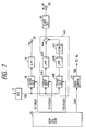
- Fig. 7 there are shown only a modified form of the cos-component extractor 40 of Fig. 6 and the associated circuit elements.
- the synchronous detector 18 for detecting, as an angular rate component (i.e. the sin ⁇ component), the third harmonic component (the component of the frequency 3 ⁇ p ) in the output of the photodetector 17 performs the synchronous detection with the reference signal Sr of a frequency which is three times higher than the phase modulation frequency ⁇ p and is provided from the reference signal generator 24, and the low-pass filter 19 removes the alternating components to extract, as the FOG output Vo, the angular rate component converted Into a DC component (i.e., KJ3sin ⁇ ).
- a DC component i.e., KJ3sin ⁇
- the cos-component extractor 40 synchronously detects components of second and fourth harmonics 2 ⁇ p and 4 ⁇ p in the output of the photodetector 17 by synchronous detectors 41A and 41B which are supplied with reference signals S r2 and S r4 of the frequencies 2 ⁇ p and 4 ⁇ p from the reference signal generator 24, respectively, and low-pass filters 42A and 42B extract second and fourth harmonic components, that is, KJ2cos ⁇ and KJ4cos ⁇ , respectively.
- the fourth harmonic component thus extracted is multiplied by 2.06 in a multiplier.
- the multiplied output is added to the second harmonic component in an adder 44 and the added output is provided as the cos-component output V cos .
- the method that uses the output V cos as the self-diagnosis signal output Vd to make a self-diagnosis is not so high in accuracy, since the output changes when the input angular rate ⁇ is applied, but this method can be utilized as a simple and easy method for making a check to see if the fiber optic gyro is operating at intended performance.
- the output Vo expressed by Eq. (2) and the output V cos expressed by Eq. (5) are squared by multipliers 25 and 26, respectively, and the both squared outputs are added by an adder 27 as depicted in Fig. 8A.
- Fig. 8A is ideally capable of completely eliminating the influence of the input angular rate but may also be so constructed as to lessen the influence of the input angular rate as predetermined within the practical range of the phase difference ⁇ .
- Two examples of such a construction are shown in Figs. 8B and 8C corresponding to Fig. 8A.
- the output Vo is squared by the multiplier 25 and the output signal of an amplifier 29a which multiplies the squared output by Ka and the output V cos of the cos-component extractor 40 are added by the adder 27.
- V o2 V cos + Ka ⁇ V o 2 (7)
- the output V o2 becomes as follows:
- V o2 K ⁇ (cos ⁇ + Ka ⁇ sin2 ⁇ ) (8)
- a decrease in the cos ⁇ component by the occurrence of the phase difference ⁇ is compensated for by the sin2 ⁇ component, and by a suitable selection of the value Ka to adjust the compensation value, the influence of the input angular rate on the self-diagnosis signal can be lessened.
- the self-diagnosis circuit 30 which is used to determine whether the level of each self-diagnosis signal Vd is within a prescribed range, can easily be formed by, for instance, window comparators each of which has positive and negative reference levels with respect to an ideal value of the respective self-diagnosis signal level and outputs a logical value, for example, a "0" or "1", depending upon whether the self-diagnosis signal level is within the reference level or not, as is the case with the example of Fig. 5.
- This feature can be equipped in the host system using the fiber optic gyro but it may also be incorporated in the fiber optic gyro itself.
- Figs. 6 and 7 the self-diagnosis circuit 30, which is used to determine whether the level of each self-diagnosis signal Vd is within a prescribed range, can easily be formed by, for instance, window comparators each of which has positive and negative reference levels with respect to an ideal value of the respective self-diagnosis signal level and outputs a logical value, for example, a "
- the diagnosis circuit 30 may be formed by the window comparators of the positive polarity side in Fig. 5.
- the calculations or arithmetic operations in the above description can be executed by hardware and it is also possible to process the sin ⁇ and cos ⁇ components by a computer, dynamic support program or similar software by converting them to digital form.
- the light I from the light source 11 is supplied via the optical coupler 12, the polarizer 13 and the optical coupler 14 to the opposite ends of the optical fiber coil 16.
- the clockwise and counterclockwise light beams CW and CCW which propagate through the optical fiber coil 15 are phase modulated by the phase modulator 16 placed at one end of the optical fiber coil 16.
- the phase-modulated CW and CCW light beams are combined by the optical coupler 14 and interfere with each other.
- the output of the photodetector 17 is input into the synchronous detector 18 (which is assumed to include the low-pass filter 19 for removing the AC component in Fig. 2, for instance), wherein the same component as that of the phase modulation frequency ⁇ p , that is, the fundamental frequency component in Eq. (1), is extracted by a synchronous detection with the reference signal Sr from the reference signal generator 24.
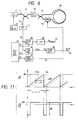
- the phase difference ⁇ f is one that is developed by shifting the phase of each light beam at a fixed rate by a feedback phase modulator 51 disposed at one end of the optical fiber coil 15.
- a ramp signal S rmp is applied to the feedback phase modulator 51 to cause it to shift the phase of light.
- the CCW light beam develops phase shift as indicated by the solid line in Fig. 11, Row A, whereas the CW light beam is similarly phase shifted after the time ⁇ for the propagation of light through the optical fiber coil 15, as indicated by the broken line.
- the both light beams have a fixed phase difference ⁇ f as shown in Fig. 11, Row B.
- the input to the integrator 52 that is, the output Vo of the synchronous detector 18 expressed by Eq. (2) converges to zero, establishing a closed loop.
- the signal Vd at the terminal 21B may also be used as the FOG output.
- the integrator 52 and the ramp signal generator 53 constitute a feedback path of the closed loop.
- the reference signal generator 24 is made up of the clock circuit or an oscillator 24A for generating the secondary reference signal of the frequency 2 ⁇ p twice higher than the phase modulation frequency ⁇ p and the frequency divider 24B which frequency divides the secondary reference signal Sr down to 1/2, providing the primary reference signal S r1 of the frequency ⁇ p .
- the frequency divided output i.e. the primary reference signal S r1
- the secondary reference signal S r2 is provided to the terminal b side.
- the switch SW1 responds to the diagnosis instruction signal CTL1 from the diagnosis circuit 30 to selectively apply either one of the primary and secondary reference signals S r1 and S r2 , as the reference signal Sr, to the synchronous detector 18.
- the rectangular wave of the frequency ⁇ p from the frequency divider 24B is also supplied to the phase modulator driver 22, wherein it is converted into a sine-wave signal and adjusted in level.
- the level-adjusted sine-wave signal is applied as the drive signal Sp to the phase modulator 16.
- the switch SW1 is held at the terminal a side, through which the signal S r1 of the same frequency as the phase modulation frequency ⁇ p is applied as the reference signal Sr to the synchronous detector 18.
- the fundamental frequency component (the frequency ⁇ p component) contained in the interference light is synchronously detected and the detected output Vo is provided to the integrator 52.
- the output Vo of the synchronous detector 18 in this case is expressed by Eq. (2) and the frequency f R of the FOG output R OUT takes a value corresponding to the angular rate expressed by Eq. (13)'.
- the frequency f R Of the ramp signal S rmp in this instance will hereinafter be referred to as a bias frequency f b , which is expressed by the following equation, using Eq. (12).
- the bias frequency f b C/(4n a L) (15)
- the bias frequency f b given by Eq. (15) is generated when no input angular rate is being applied.
- the velocity of light C, the refractive index n a of the optical fiber and the length L of the optical fiber in Eq. (15) are all factors of small temperature coefficients, and hence remain substantially constant when the operation of the fiber optic gyro is normal; therefore, the ramp signal S rmp of the bias frequency f b can be used as a high precision diagnosis signal.
- the ramp signal S rmp of the bias frequency f b is applied to the diagnosis circuit 30, which makes a check to see if the bias frequency f b is within a predetermined range and, if not, outputs the alarm signal ALM.
- the diagnosis circuit 30 may be formed to have a construction in which the ramp signal S rmp is converted by a frequency-to-voltage converter (F/V converter) into a voltage proportional to its frequency and the voltage is checked by, for example, the positive window comparator (CM1, CM2, G1) in Fig. 5 as to whether or not it is within a predetermined range.
- F/V converter frequency-to-voltage converter
- the circuit 30 may have a construction in which the number of pulses of the ramp signal S rmp is counted by a counter for each fixed period to obtain a value corresponding to the frequency of the ramp signal S rmp and it is checked by digital operation whether or not the value is within a predetermined range.
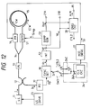
- Fig. 12 illustrates another embodiment of the present invention wherein, as is the case with the Fig. 3 embodiment, the inverter 24C for inverting the phase of the reference signal S r1 is included in the reference signal generator 24 and the non-phase-inverted reference signal and the phase-inverted reference signal are provided to the terminals a and b of the switch SW2, respectively.
- the reference signal S r1 that the reference signal generator 24 is a reference signal of an odd harmonic frequency which is the same as the frequency ⁇ p , for example.
- the switch SW2 is connected to the terminal a side, a signal of the same frequency as the phase modulation frequency ⁇ p is applied as the reference signal Sr to the synchronous detector 18.
- the output of the synchronous detector 18 in this case is expressed by Eq. (2) and the frequency f R of the FOG output R OUT takes a value corresponding to the angular rate shown in Eq. (13)'.
- the switch SW2 When the switch SW2 is changed over to the terminal b side in response to the diagnosis instruction signal CTL2 from the diagnosis circuit 30, the reference signal S r1 is phase shifted 180° by the inverter 24C and applied to the synchronous detector 18.
- f b C/(2n a L) (16)
- the velocity of light C, the refractive index n a of the optical fiber and the length L of the optical fiber are all factors of small temperature coefficients, and hence remain substantially unchanged when the operation of the fiber optic gyro is normal; therefore, the ramp signal S rmp of the bias frequency f b can be used a high precision diagnosis signal.
- the output R OUT of the ramp signal generator 53 is applied to the diagnosis circuit 30, which makes a check to see if the bias frequency is within a given range and, if not, delivers the alarm signal ALM to the outside.
- Fig. 13 illustrates the principal part of a modification of the Fig. 10 embodiment, wherein, as is the case with Fig. 3, the switch SW2 and the inverter 24C are provided to invert the phase of the secondary reference signal S r2 , thereby inverting the polarity of the synchronously detected output.
- the input angular rate is detected in the state in which the switch SW1 is connected to the terminal a side under the control of the first diagnosis instruction signal CTL1, and the self-diagnosis is made in the state in which the switch SW1 is connected to the terminal b side.
- the self-diagnosis operation is the same as that when the switch SW1 is connected to the terminal a side in Fig. 10 (The phase difference ⁇ at the operating point is ⁇ /2.) and when no angular rate is being applied, the output R OUT of the frequency f b expressed by Eq. (15) is provided to the output terminal 21A (Fig. 10).
- the secondary reference signal S r2 is inverted in phase by the inverter 24C and applied therefrom to the synchronous detector 18, and consequently, the polarity of the synchronously detected output Vo expressed by Eq. (14) is inverted.
- the ramp signal S rmp is obtained which is equal in absolute value and opposite in polarity to the FOG output R OUT which is provided when the phase difference ⁇ at the operating point is ⁇ /2 (the switch SW2 being connected to the terminal a side) under the condition that the Sagnac phase difference ⁇ s is zero.
- the ramp signal S rmp is provided as the self-diagnosis signal to the diagnosis circuit 30.
- the diagnosis circuit 30, which judges from the diagnosis signals R OUT and Vd whether the frequency f b of the feedback signal S rmp is within the prescribed value, may be provided outside the fiber optic gyro, for example, in the host system.
- the check of the bias frequency f b by the diagnosis circuit 30 is made, for example, simultaneously with the checking of other aircraft instruments of the aircraft loaded with this fiber optic gyro prior to its takeoff.
- the provision of the self-diagnosis feature in the fiber optic gyro enables it to detect an abnormality or failure or delivers an alarm signal for a self-diagnosis when the fiber optic gyro operates at degraded performance or its function is impaired by a fault, thereby ensuring that the host system using the fiber optic gyro avoids from a danger.
Landscapes
- Physics & Mathematics (AREA)
- Engineering & Computer Science (AREA)
- Optics & Photonics (AREA)
- Electromagnetism (AREA)
- Power Engineering (AREA)
- General Physics & Mathematics (AREA)
- Radar, Positioning & Navigation (AREA)
- Remote Sensing (AREA)
- Gyroscopes (AREA)
Priority Applications (1)
| Application Number | Priority Date | Filing Date | Title |
|---|---|---|---|
| EP96100077A EP0725261B1 (fr) | 1992-04-30 | 1993-04-30 | Capteur de vitesse angulaire d'un interféromètre optique avec autodiagnostique |
Applications Claiming Priority (6)
| Application Number | Priority Date | Filing Date | Title |
|---|---|---|---|
| JP111575/92 | 1992-04-30 | ||
| JP11157592A JP2514528B2 (ja) | 1992-04-30 | 1992-04-30 | 自己診断機能を有した光干渉角速度計 |
| JP12345192A JP2514529B2 (ja) | 1992-05-15 | 1992-05-15 | 光干渉角速度計 |
| JP12345092 | 1992-05-15 | ||
| JP123450/92 | 1992-05-15 | ||
| JP123451/92 | 1992-05-15 |
Related Child Applications (2)
| Application Number | Title | Priority Date | Filing Date |
|---|---|---|---|
| EP96100077A Division EP0725261B1 (fr) | 1992-04-30 | 1993-04-30 | Capteur de vitesse angulaire d'un interféromètre optique avec autodiagnostique |
| EP96100077.5 Division-Into | 1993-04-30 |
Publications (2)
| Publication Number | Publication Date |
|---|---|
| EP0568105A1 true EP0568105A1 (fr) | 1993-11-03 |
| EP0568105B1 EP0568105B1 (fr) | 1996-11-06 |
Family
ID=27311992
Family Applications (2)
| Application Number | Title | Priority Date | Filing Date |
|---|---|---|---|
| EP96100077A Expired - Lifetime EP0725261B1 (fr) | 1992-04-30 | 1993-04-30 | Capteur de vitesse angulaire d'un interféromètre optique avec autodiagnostique |
| EP93107088A Expired - Lifetime EP0568105B1 (fr) | 1992-04-30 | 1993-04-30 | Capteur de vitesse angulaire d'un interferomètre optique avec autodiagnostique |
Family Applications Before (1)
| Application Number | Title | Priority Date | Filing Date |
|---|---|---|---|
| EP96100077A Expired - Lifetime EP0725261B1 (fr) | 1992-04-30 | 1993-04-30 | Capteur de vitesse angulaire d'un interféromètre optique avec autodiagnostique |
Country Status (3)
| Country | Link |
|---|---|
| US (1) | US5386290A (fr) |
| EP (2) | EP0725261B1 (fr) |
| DE (2) | DE69322797T2 (fr) |
Cited By (1)
| Publication number | Priority date | Publication date | Assignee | Title |
|---|---|---|---|---|
| EP0685722A3 (fr) * | 1994-05-30 | 1996-08-14 | Cselt Centro Studi Lab Telecom | Méthode de mesure de l'indice de réfraction non-linéaire d'un fibre optique monomode. |
Families Citing this family (10)
| Publication number | Priority date | Publication date | Assignee | Title |
|---|---|---|---|---|
| JP3011592B2 (ja) * | 1993-11-16 | 2000-02-21 | 日立電線株式会社 | 光ファイバジャイロの故障検出方法及び故障診断装置 |
| WO1998054544A2 (fr) * | 1997-05-30 | 1998-12-03 | Honeywell Inc. | Procede et dispositif pour surveillance non intrusive en continu de bruit |
| US5999304A (en) * | 1997-08-04 | 1999-12-07 | Honeywell, Inc. | Fiber optic gyroscope with deadband error reduction |
| US6256101B1 (en) * | 1999-10-21 | 2001-07-03 | L-3 Communications Corporation | Open loop fiber optic gyroscope for measuring ultra-high rates of rotation |
| ATE443873T1 (de) | 2004-11-18 | 2009-10-15 | Powersense As | Kompensation von einfachen faseroptischen faraday-effekt-sensoren |
| JP2007040764A (ja) * | 2005-08-01 | 2007-02-15 | Toyota Motor Corp | 光ファイバジャイロの異常検出装置 |
| US8692539B2 (en) * | 2006-11-30 | 2014-04-08 | Powersense A/S | Faraday effect current sensor |
| JP4842175B2 (ja) * | 2007-03-07 | 2011-12-21 | 東京エレクトロン株式会社 | 温度測定装置及び温度測定方法 |
| US7777889B2 (en) * | 2008-08-07 | 2010-08-17 | Honeywell International Inc. | Bias-instability reduction in fiber optic gyroscopes |
| US9041934B2 (en) | 2013-10-25 | 2015-05-26 | Honeywell International Inc. | Dispersion managed interferometric fiber optic gyroscope |
Citations (1)
| Publication number | Priority date | Publication date | Assignee | Title |
|---|---|---|---|---|
| EP0462580A1 (fr) * | 1990-06-21 | 1991-12-27 | Japan Aviation Electronics Industry, Limited | Gyromètre à fibre optique avec autodiagnostic |
Family Cites Families (4)
| Publication number | Priority date | Publication date | Assignee | Title |
|---|---|---|---|---|
| US4796993A (en) * | 1987-04-13 | 1989-01-10 | Hitachi, Ltd. | Phase modulation type fiber optic gyroscope |
| JP2695018B2 (ja) * | 1989-11-09 | 1997-12-24 | 住友電気工業株式会社 | 位相変調光ファイバジャイロ補正方式 |
| JPH03214020A (ja) * | 1990-01-18 | 1991-09-19 | Sumitomo Electric Ind Ltd | 光フアイバジヤイロにおける自動位相調整回路 |
| JPH04106415A (ja) * | 1990-08-27 | 1992-04-08 | Sumitomo Electric Ind Ltd | 光フアイバジヤイロの信号処理方式 |
-
1993
- 1993-04-26 US US08/051,995 patent/US5386290A/en not_active Expired - Lifetime
- 1993-04-30 EP EP96100077A patent/EP0725261B1/fr not_active Expired - Lifetime
- 1993-04-30 DE DE69322797T patent/DE69322797T2/de not_active Expired - Fee Related
- 1993-04-30 EP EP93107088A patent/EP0568105B1/fr not_active Expired - Lifetime
- 1993-04-30 DE DE69305778T patent/DE69305778T2/de not_active Expired - Fee Related
Patent Citations (1)
| Publication number | Priority date | Publication date | Assignee | Title |
|---|---|---|---|---|
| EP0462580A1 (fr) * | 1990-06-21 | 1991-12-27 | Japan Aviation Electronics Industry, Limited | Gyromètre à fibre optique avec autodiagnostic |
Non-Patent Citations (4)
| Title |
|---|
| PATENT ABSTRACTS OF JAPAN vol. 15, no. 382 (P-1257)26 September 1991 & JP-A-03 152414 ( SUMITOMO ELECTRIC IND LTD ) 28 June 1991 * |
| PATENT ABSTRACTS OF JAPAN vol. 15, no. 495 (P-1288)13 December 1991 & JP-A-03 214020 ( SUMITOMO ELECTRIC IND LTD ) 19 September 1991 * |
| PATENT ABSTRACTS OF JAPAN vol. 16, no. 241 (P-1363)3 June 1992 & JP-A-04 052511 ( JAPAN AVIATION ELECTRON IND ) 20 February 1992 * |
| PATENT ABSTRACTS OF JAPAN vol. 16, no. 348 (P-1393)28 July 1992 & JP-A-04 106415 ( SUMITOMO ELECTRIC IND LTD ) 8 April 1992 * |
Cited By (1)
| Publication number | Priority date | Publication date | Assignee | Title |
|---|---|---|---|---|
| EP0685722A3 (fr) * | 1994-05-30 | 1996-08-14 | Cselt Centro Studi Lab Telecom | Méthode de mesure de l'indice de réfraction non-linéaire d'un fibre optique monomode. |
Also Published As
| Publication number | Publication date |
|---|---|
| EP0568105B1 (fr) | 1996-11-06 |
| DE69305778D1 (de) | 1996-12-12 |
| EP0725261B1 (fr) | 1998-12-23 |
| DE69305778T2 (de) | 1997-04-03 |
| DE69322797D1 (de) | 1999-02-04 |
| EP0725261A1 (fr) | 1996-08-07 |
| US5386290A (en) | 1995-01-31 |
| DE69322797T2 (de) | 1999-06-24 |
Similar Documents
| Publication | Publication Date | Title |
|---|---|---|
| US4883358A (en) | Fiber optic gyro stabilized by harmonic components of detected signal | |
| US7855789B2 (en) | RFOG modulation error correction | |
| EP0568105B1 (fr) | Capteur de vitesse angulaire d'un interferomètre optique avec autodiagnostique | |
| EP0730725A1 (fr) | Reduction de bruit optique | |
| JPH047931B2 (fr) | ||
| US7336364B2 (en) | Minimal bias switching for fiber optic gyroscopes | |
| EP0462580B1 (fr) | Gyromètre à fibre optique avec autodiagnostic | |
| EP0386739B1 (fr) | Gyroscope à fibre optique avec modulation de phase | |
| US5384637A (en) | Fiber optic gyroscope modulation amplitude control | |
| US5009480A (en) | Fiber optic gyro | |
| US5031988A (en) | Fiber optic gyro | |
| EP0535164B1 (fr) | Demodulation de source de signaux de reference | |
| US5098188A (en) | Method and apparatus for eliminating kerr effects in a ring gyro | |
| CA2061772C (fr) | Demodulateur synchrone | |
| US5345307A (en) | Linear phase ramp type fiber optic gyro having ramp reset and reset connection signals | |
| JPH048727B2 (fr) | ||
| JP2514529B2 (ja) | 光干渉角速度計 | |
| JPS63128225A (ja) | 変調式光フアイバジヤイロ | |
| EP0492580B1 (fr) | Gyroscope à fibre optique | |
| RU2793727C1 (ru) | Датчик угловой скорости | |
| JP2006177893A (ja) | 光干渉角速度計 | |
| JP2649310B2 (ja) | 自己診断機能を有する光干渉角速度計 | |
| JP2894824B2 (ja) | 光ファイバジャイロの零オフセット消去方法 | |
| JPH02236112A (ja) | 位相変調方式光フアイバジヤイロ | |
| JPH05306938A (ja) | 自己診断機能を有した光干渉角速度計 |
Legal Events
| Date | Code | Title | Description |
|---|---|---|---|
| PUAI | Public reference made under article 153(3) epc to a published international application that has entered the european phase |
Free format text: ORIGINAL CODE: 0009012 |
|
| 17P | Request for examination filed |
Effective date: 19930430 |
|
| AK | Designated contracting states |
Kind code of ref document: A1 Designated state(s): DE FR GB |
|
| 17Q | First examination report despatched |
Effective date: 19950503 |
|
| GRAG | Despatch of communication of intention to grant |
Free format text: ORIGINAL CODE: EPIDOS AGRA |
|
| GRAH | Despatch of communication of intention to grant a patent |
Free format text: ORIGINAL CODE: EPIDOS IGRA |
|
| GRAH | Despatch of communication of intention to grant a patent |
Free format text: ORIGINAL CODE: EPIDOS IGRA |
|
| GRAA | (expected) grant |
Free format text: ORIGINAL CODE: 0009210 |
|
| AK | Designated contracting states |
Kind code of ref document: B1 Designated state(s): DE FR GB |
|
| XX | Miscellaneous (additional remarks) |
Free format text: TEILANMELDUNG 96100077.5 EINGEREICHT AM 04/01/96. |
|
| ET | Fr: translation filed | ||
| REF | Corresponds to: |
Ref document number: 69305778 Country of ref document: DE Date of ref document: 19961212 |
|
| PLBE | No opposition filed within time limit |
Free format text: ORIGINAL CODE: 0009261 |
|
| 26N | No opposition filed | ||
| REG | Reference to a national code |
Ref country code: GB Ref legal event code: IF02 |
|
| PGFP | Annual fee paid to national office [announced via postgrant information from national office to epo] |
Ref country code: FR Payment date: 20040330 Year of fee payment: 12 |
|
| PGFP | Annual fee paid to national office [announced via postgrant information from national office to epo] |
Ref country code: GB Payment date: 20040428 Year of fee payment: 12 |
|
| PGFP | Annual fee paid to national office [announced via postgrant information from national office to epo] |
Ref country code: DE Payment date: 20040429 Year of fee payment: 12 |
|
| PG25 | Lapsed in a contracting state [announced via postgrant information from national office to epo] |
Ref country code: GB Free format text: LAPSE BECAUSE OF NON-PAYMENT OF DUE FEES Effective date: 20050430 |
|
| PG25 | Lapsed in a contracting state [announced via postgrant information from national office to epo] |
Ref country code: DE Free format text: LAPSE BECAUSE OF NON-PAYMENT OF DUE FEES Effective date: 20051101 |
|
| GBPC | Gb: european patent ceased through non-payment of renewal fee |
Effective date: 20050430 |
|
| PG25 | Lapsed in a contracting state [announced via postgrant information from national office to epo] |
Ref country code: FR Free format text: LAPSE BECAUSE OF NON-PAYMENT OF DUE FEES Effective date: 20051230 |
|
| REG | Reference to a national code |
Ref country code: FR Ref legal event code: ST Effective date: 20051230 |