EP0568700A1 - Strickentwurfsystem und verfahren zur herstellung von strickdaten dafür - Google Patents
Strickentwurfsystem und verfahren zur herstellung von strickdaten dafür Download PDFInfo
- Publication number
- EP0568700A1 EP0568700A1 EP92920035A EP92920035A EP0568700A1 EP 0568700 A1 EP0568700 A1 EP 0568700A1 EP 92920035 A EP92920035 A EP 92920035A EP 92920035 A EP92920035 A EP 92920035A EP 0568700 A1 EP0568700 A1 EP 0568700A1
- Authority
- EP
- European Patent Office
- Prior art keywords
- knitting
- data
- fabric
- information
- stitch
- Prior art date
- Legal status (The legal status is an assumption and is not a legal conclusion. Google has not performed a legal analysis and makes no representation as to the accuracy of the status listed.)
- Granted
Links
Images











Classifications
-
- D—TEXTILES; PAPER
- D04—BRAIDING; LACE-MAKING; KNITTING; TRIMMINGS; NON-WOVEN FABRICS
- D04B—KNITTING
- D04B15/00—Details of, or auxiliary devices incorporated in, weft knitting machines, restricted to machines of this kind
- D04B15/66—Devices for determining or controlling patterns ; Program-control arrangements
- D04B15/68—Devices for determining or controlling patterns ; Program-control arrangements characterised by the knitting instruments used
- D04B15/78—Electrical devices
-
- D—TEXTILES; PAPER
- D04—BRAIDING; LACE-MAKING; KNITTING; TRIMMINGS; NON-WOVEN FABRICS
- D04B—KNITTING
- D04B37/00—Auxiliary apparatus or devices for use with knitting machines
- D04B37/02—Auxiliary apparatus or devices for use with knitting machines with weft knitting machines
-
- D—TEXTILES; PAPER
- D04—BRAIDING; LACE-MAKING; KNITTING; TRIMMINGS; NON-WOVEN FABRICS
- D04B—KNITTING
- D04B15/00—Details of, or auxiliary devices incorporated in, weft knitting machines, restricted to machines of this kind
- D04B15/66—Devices for determining or controlling patterns ; Program-control arrangements
-
- D—TEXTILES; PAPER
- D04—BRAIDING; LACE-MAKING; KNITTING; TRIMMINGS; NON-WOVEN FABRICS
- D04B—KNITTING
- D04B7/00—Flat-bed knitting machines with independently-movable needles
- D04B7/24—Flat-bed knitting machines with independently-movable needles for producing patterned fabrics
- D04B7/28—Flat-bed knitting machines with independently-movable needles for producing patterned fabrics with stitch patterns
Definitions
- the present invention relates to a knit design system and method for preparing knitting data thereof, wherein control data for instructing a knitting machine is created, and the state of a finished fabric can be learned by a display.
- test knitting must be carried out by the machine to determine whether or not the set control data is correct or the desired knit state is achieved. For this reason, test knitting and correction of the set control data must be conducted a plurality of times before entering into mass-production. Thus, a tedious work is required to set the final control data for the knitting machine.
- a recording device of pattern information described in U.S. Patent No. 4,608,642 displays stitches on a display screen, wherein the information instructing the knitting operation is inputted in the form of color codes. After that, the recording device prepares control procedure data for the knitting machine according to the color codes inputted.
- the recording device in U.S. Patent No. 4,608,642 poses a problem in that it requires greater operator's skill for setting the control data as the stitch structure becomes complicated.
- a first object of the present invention is to provide a knit design system which can reduce the repetition frequency of the test knitting, and enables the operator to learn the state of a finished fabric before actually knitting on the machine.
- a second object of the present invention is to provide a knit design system and method for preparing knitting data for the same, which can readily prepare control data to be set to the knitting machine.
- a knit design system comprising: input means for inputting design information that indicates a shape of a fabric to be knitted and a stitch structure; first storage means for storing first calculation information indicating correspondence between the design information and operation information indicating a content of a knitting operation of a knitting machine; and first calculation processing means for converting the design information inputted from the input means to the operation information on the basis of the first calculation information in the first storage means.
- a knit design system comprising in addition to the first aspect of the present invention: second storage means for storing for each type of knitting machines second calculation information indicating a correspondence between the operation information and control information for driving the knitting machine; designation means for designating a type of the knitting machine; and second calculation means for converting operation information which has been converted by the first calculation means into the control information corresponding to the designated machine type on the basis of the second calculation information in the second storage means corresponding to the designated machine type.
- a knit design system comprising: retaining means for storing and retaining the design information inputted, the operation information prepared, and the control information prepared, in the second aspect of the present invention; and correction means for correcting information stored in the retaining means, wherein the correction means can serve the information corrected to the first calculation means when the information corrected is the design information, and can serve the information corrected to the second calculation means when the information corrected is the operation information.
- a knit design system comprising: third storage means for storing image information indicating a stitch structure in a plurality of graphic patterns; input means for inputting design information indicating a shape of a fabric to be knitted and a stitch structure; first image processing means for forming a contour image corresponding to a shape indicated by the design information inputted; second image processing means for preparing a stitch image by using the plurality of graphic patterns corresponding to a structure indicated by the design information inputted from the input means; third image processing means for synthesizing the stitch image prepared and the contour image in order to prepare a fabric image; and display means for displaying the fabric image prepared.
- a knit design system wherein the second image processing means in the fourth aspect of the present invention selects the graphic patterns externally instructed, and displays on the display means a fabric image by using only graphic patterns selected.
- a knit design system wherein the third image processing means in the fourth aspect of the present invention scales up or down the fabric image prepared.
- a knit design system wherein the third image processing means in the fourth aspect of the present invention prepares the stitch image for front portion and back portion of the fabric, respectively.
- a knitting data preparation method comprising the steps of: predetermining a first correspondence between a plurality of first characteristic parameters indicating a stitch structure and a plurality of second characteristic parameters indicating a knitting operation of stitches; storing expansively on a memory the plurality of first characteristic parameters associated with a fabric in a manner that each of the plurality of first characteristic parameters corresponds to each one of positions of stitches constituting the fabric to be knitted; reading by using a searching processing of a calculation unit the plurality of first characteristic parameters successively along a knitting direction of a yarn, the reading being performed with regard to positions of stitches continuously formed by the same yarn in the fabric; and preparing knitting data indicating a knitting procedure of the fabric by converting the plurality of first characteristic parameters which have been read to the plurality of second characteristic parameters according to the first correspondence by using a calculation processing of the calculation unit.
- a knitting data preparation method comprising, in addition to the steps of the eighth aspect, the steps of: predetermining a second correspondence between a plurality of control parameters designating a knitting operation of a knitting machine and the plurality of second parameters; rearranging the plurality of second characteristic parameters in a knitting sequence of the knitting machine by the calculation unit; and converting by the calculation processing of the calculation unit the plurality of second characteristic parameters which have been rearranged to the plurality of control parameters according to the second correspondence, so that second knitting data for controlling the knitting machine is prepared.
- a computer program product for use with a knit design system, having a computer usable medium including computer readable program code means embodied in the medium for causing the computer to convert first characteristic parameters indicating a structure of a stitch to second characteristic parameters indicating a knitting operation of the stitch, the computer program product comprising: first computer readable program code means for causing the computer to define a correspondence between the first characteristic parameters and the second characteristic parameters; second computer readable program code means for causing the computer to store expansively on a memory in the computer the plurality of first characteristic parameters associated with a fabric in a manner that each of the plurality of first characteristic parameters corresponds to each position of stitches constituting the fabric to be knitted; third computer readable program code means for causing the computer to read by using a search processing of the computer the plurality of first characteristic parameters from the memory along a knitting direction of a yarn in a manner that each of the plurality of first characteristic parameters to be read corresponds to each of positions of stitches that are continuously formed by the
- a computer program product comprising in addition to the tenth aspect of the present invention: fifth computer readable program code means for causing the computer to define a second correspondence between a plurality of control parameters designating a knitting operation of a knitting machine and the plurality of second characteristic parameters; sixth computer readable program code means for causing the computer to rearrange the second characteristic parameters to a knitting sequence of the knitting machine; and seventh computer readable program code means for causing the computer to convert the plurality of second characteristic parameters which have been rearranged to the plurality of control parameters according to the second correspondence.
- the operation information indicating the knitting operation of knitting needles and the like is prepared from the design information such as a stitch length, a type of stitches and the like.
- control information for operating knitting needles and the like is prepared from the operation information.
- the operator can prepare new control information by correcting the design information and the operation information which are used in preparing the control information.
- the operator can observe the state of a finished fabric of the knitting using the design information by merely inputting the design information of the fabric.
- the entire structure of a fabric can be readily learned since particular design information, which indicates various structural details such as a stitch type, a relationship of connection between stitches, and the like, is displayed individually in graphic patterns.
- the front portion and the back portion can be displayed, the actual knit state of the entire fabric is well shown.
- the structural contents of the entire fabric is stored in the memory by storing the first characteristic parameters in such a manner that they correspond to respective stitches, considering the fact that the structure of a single stitch has one-to-one correspondence with the operation of a knitting needle that knits that stitch structure.
- a series of the first characteristic parameters arranged in accordance with the sequence of the knitting operation is prepared by extracting, from an information group of the first characteristic parameters stored on the memory, the first characteristic parameters at a position where a stitch such as a loop is formed, along the knitting direction of the yarn.
- the knitting data which represent the knitting procedure of the entire fabric such as the sequence of the operation of knitting needles, is prepared by converting each of the series of the first characteristic parameters to the second characteristic parameter.
- control parameters for operating the knitting needles of an actual knitting machine is prepared according to the second characteristic parameters, for instance, the moving sequence of the knitting needles.
- the processing steps described in the eighth aspect of the present invention are implemented by a software processing of the computer.
- the processing steps described in the ninth aspect of the present invention are implemented by a software processing of the computer.
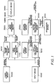
- Fig. 1 shows a basic construction of an embodiment according to the present invention.
- the numeral 1000 indicates an input means for inputting design information instructing a shape and stitch structure of a fabric to be knitted.
- the numeral 1100 indicates a first storage means for storing first calculation information instructing a correspondence relation between the design information and the operation information providing the contents of the knitting operation of a knitting machine.
- the numeral 1200 indicates a first calculation means for converting the design information inputted from the input means to the operation information according to the first calculation information of the first storage means.
- the numeral 2000 indicates a second storage means for storing, for each type of the knitting machines, second calculation information indicating a correspondence relation between the operation information and the control information for driving the knitting machine.
- the numeral 2100 indicates designation means for designating a machine type of the knitting machine.
- the numeral 2200 indicates a second calculation means for converting the operation information that has been converted by the first calculation means into the control information corresponding to the designated machine type according to the second calculation information in the second storage means corresponding to the designated machine type.
- the numeral 3000 indicates a third storage means for storing image information representing stitch structures in terms of a plurality of graphic patterns.
- the numeral 3100 indicates a first image processing means for forming a contour image corresponding to the shape indicated by the design information which has been inputted from the input means.
- the numeral 3200 indicates a second image processing means for preparing a stitch image using the plurality of graphic patterns corresponding to the structure indicated by the design information which has been inputted from the input means.
- the numeral 3300 indicates a third image processing means for preparing a fabric image by combining the stitch image prepared and the contour image.
- the numeral 3400 indicates a display means for displaying the prepared fabric image.
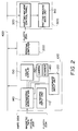
- a CAD system 100 for conducting the design of fabrics a personal computer 200 for assisting the system processing, and a knitting machine, which are associated with the present invention, are connected in the form of a network through a communication cable 400.
- the CAD system 100 mainly comprises a keyboard input unit 110, a coordinate input unit 120 such as a mouse, a color display (display unit) 130, and an engineering workstation 140.
- the CAD system is detachably provided with an electronic camera 150, a scanner 160, a portable storage medium such as a floppy disk and the like.
- the operator uses the keyboard input unit 110 and the coordinate input unit 120 to input various data (design information) on the design of the fabric.
- the color display 130 (the display unit) displays the input data and the states of the designed fabric. As will be described later, the color display 130 displays, according to the operator's instruction, knitting procedure data (sequence data, the operation information of the first aspect of the present invention) which have been converted from the input data by the engineering workstation 140, or the control data for controlling the drive of the knitting machine 300.
- Any type of known image processing unit that can perform image reduction, enlargement and the preparation of a graphic image can be used as the engineering workstation 140.
- the camera 150 and the scanner 160 are used for picking up an imaging of a fabric, and inputting the image to the engineering workstation 140, respectively.
- the knitting machine comprises a knitting machine main unit 310 and a knitting machine control panel 320.
- the knitting machine control panel 320 is provided with the drive control data inputted through the communication cable 400 or with the drive control data stored on a portable storage medium such as a floppy disk, and drives the knitting machine main unit according to the driving control data. Since a conventional type knitting machine 300 known in the art, such as that described in U.S. Patent No. 4,768,357, can be employed as the knitting machine 300, the details thereof are not described here in detail.
- FIG. 3 An example of the construction of the engineering workstation 140 is shown in Fig. 3.
- a central processing unit (CPU) 141 conducts an information transfer processing with various devices connected via a bus, in accordance with a system program stored on a read only memory (ROM) 142.
- the CPU 141 also reads programs (first and second calculation information of the first and second aspects of the present invention) for fabric design from the floppy disk set in a floppy disk storage unit (FDD) 145, and loads them on a random access memory (RAM) 143.
- the CPU 141 executes, according to the programs on the RAM 143, a fabric design processing, a preparation processing of the knitting procedure, and a preparation of the knitting machine control data, which will be described below.
- the CPU 141 operates as the first and second calculation means (the first calculation means 1200 and the second calculation means 2200 shown in Fig. 1) of the first and second aspects of the present invention.
- a video RAM 146 has an area for storing image information to be displayed on the color display 130 and a synthesizing area for preparing the image information.
- the display image information on the video RAM 146 is read by the CPU 141, and is outputted to the color display 130 through an output interface 147.
- Information on fabric design which has been instructed by the operator using the keyboard input unit 110 and the coordinate input unit 120, is transferred to the CPU 141 through an input interface 144.
- the input interface 144 can also be connected to the camera 150 and the scanner 160.
- the keyboard input unit 110 and the coordinate input unit 120 operate as the input means (input means 1000 in Fig. 1) of the first aspect of the present invention, and as the designation means (designation means 2100 in Fig. 1) of the first aspect of the present invention.
- the operator prepares the control data indicating the knitting procedure of the fabric and the drive control data for the knitting machine 300 by using the CAD system 100.
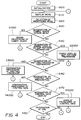
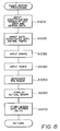
- the main control procedure for executing this processing is shown in Fig. 4.
- This control procedure has been stored in a floppy disk in advance, and is transferred to the program memory in the engineering workstation 140 in response to a start (read) instruction from the keyboard input unit 110 when the floppy disk is set into the engineering work station.
- the main control procedure shown in Fig. 4 is then executed by the microprocessor or the central processing unit (CPU 141 in Fig. 3) in the engineering workstation 140 in response to a processing instruction from the keyboard input unit 110.
- the engineering workstation 140 initializes various devices in the machine and various data values necessary for the processing in response to a control procedure start instruction in Fig. 4 (step S100).
- the menu is then displayed on the color display 130 to prompt the operator to select a processing menu (step S110).
- the present embodiment has the following processing menu.
- the operator selects a desired processing menu from the above-mentioned menu by designating the menu position by the cursor on the display screen of the color display 130 by means of the coordinate input unit 120 (step S120).
- the engineering workstation 140 reads from an internal program memory a sub-processing procedure corresponding to the selected processing menu (except for end processing), and executes it. When the processing of the selected processing menu has been completed, the execution procedure of the engineering workstation 140 returns to step S110, where the menu is displayed, and the operator selects another menu processing.
- a fabric example as shown in Fig. 5 is to be designed.
- numerals that are placed between arrows in the vertical or horizontal direction indicate the number of stitches.
- Numerals including "-" symbols like 6-2-3 indicate that a step is repeated three times, in which the number of stitches is decreased (or increased) by two stitches when 6 courses are knitted.
- Fig. 6 The dimensions of the fabric are assumed to take values as shown in Fig. 6.
- the position numbers are an identification number affixed to the position designated by a shape input processing which will be described later.
- the engineering workstation 140 transfers its processing to the control procedure of Fig. 8, and displays an image as shown in Fig. 9 on the color display 130. At this point, the contour image A of the shape input window for inputting the shape information is not displayed.
- the operator moves the cursor onto the size button (not shown) in the window for menu selection shown in Fig. 9 by the coordinate input unit 120, and sets the mode for inputting the size data and the stitch structure. Then, the operator enters identification names of the data to be inputted henceforth from the keyboard input unit 110 (step S1010).
- the input data includes: A unit of a size input; Stitch length of the entire fabric; Parameter values indicating the knitting manner of one stitch (see, Figs. 23 and 24, details thereof will be described later); A yarn number used for knitting, a link start position, and an end position.
- the engineering workstation 140 stores the input data into the internal memory every time the input data is entered from the keyboard input unit 110.
- the operator moves the cursor along the contour in Fig. 9 on the display screen of the color display 130 by using the coordinate input unit 120 so that the contour image is displayed on the display screen, and the shape is inputted (step S1030).
- the inputted shape is stored in the engineering workstation 140 in the form of a two-dimensional dot pattern.
- the operator sets the size input mode by pointing with the cursor a size input switch (function) in a size data input window on the display screen, and then inputs the fabric sizes (Fig. 6) at various locations of the contour pattern A on the display screen, as well as common input data and their positions by using the coordinate input unit 120 and the keyboard input unit 110 (step S1040).
- the common input data includes, for example, structural data of one stitch (which will be described later), a type of narrowing, the number of stitches of the narrowing, the stitch length of the narrowing, a linking type, and linking stitch length.
- the operator sets the input mode for a bottom rib stitch, inputs the range of the rib stitch (called a "rib range") as shown in Fig. 11 by the coordinate input unit 120, and designates a type of the rib stitch (e.g. a type of the rib, a stitch length of the rib) by an indication switch in the size data input window (step S1050).
- a rib range e.g. a type of the rib, a stitch length of the rib
- the input data described above are stored in exclusive storage area in the memory of the engineering workstation 140: the shape data is stored in the form of dot patterns or in terms of end point position data; and the other input data is stored in the form of numerical values or identification symbols.
- the common data relating to the stitches is stored expansively in the memory for individual stitch positions in the fabric.
- the CPU whose numerical reference is 141; hereinafter the reference is omitted
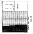
- the engineering workstation 140 reads size data in the memory, creates in the memory (RAM 143) a contour image showing the actual shape in proportion to the sizes, and displays it in the shape input window of the color display 130 as shown in Fig. 12 (step S160).
- the CPU in the engineering workstation 140 stores the input design data (size data, stitch-related data) on a floppy disk (FD) (step S1070). After that, the CPU of the engineering workstation 140 completes the control procedure in Fig. 8, returns to the menu display processing of step S110 in Fig. 4, and waits for the operator's selection of another menu item.
- FD floppy disk
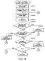
- the control procedure of Fig. 13 is executed by the engineering workstation 140.
- the identification name of the fabric data that has been prepared in the above fabric design processing and stored on the floppy disk, is read by the engineering workstation 140, and is displayed on the color display 130 (step S2010).
- the operator specifies a desired data name with the cursor moved by the coordinate input unit 120.
- the engineering workstation 140 reads the fabric data corresponding to the specified fabric data name (design data name) from the floppy disk, and loads (stores) it in the internal memory (step S2020).
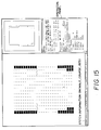
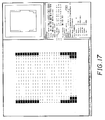
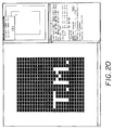
- the engineering workstation 140 then divides the display screen of the color display 130 into three window area, that is, a fabric canvas area, an operation panel area, and a layout canvas area, and displays the following patterns and images in the individual areas.
- the fabric canvas area displays an enlarged fabric image of a specified part of the contour image showing the fabric shape displayed in the layout canvas area.
- the layout canvas area displays in a reduced form the shape data (Fig. 12) included in the selected fabric data.
- the operation panel window displays not only various switches that are used for the data input in the knit pattern design, but also switch groups for inputting instructions associated with the display, such as enlargement, reduction, movement, and the like of the fabric canvas area.
- These display functions are selected by specifying a function selection switch on the operation panel using the coordinate input unit 120.
- the operator uses the above display functions in order to correct the inputted data while confirming the fabric state and the design data inputted on the display screen, and to design the knit pattern.
- the CPU of the engineering workstation 140 identifies the content of an instruction inputted from the keyboard input unit 110 or from an instruction switch on the display screen, and conducts the display processing according to the individual instruction contents (step S2500, which will be described later), data correction processing (step S2065), and other processings (step S2075).
- the data correction processing is performed by overwriting the inputted attribute information to be used for correction and to be used for correction and to be associated with the design data, on the attribute information that has been stored in the internal memory of the engineering workstation 140.
- the CPU and the keyboard input unit correspond to the correction means of the third aspect of the present invention.
- the engineering workstation 140 has other processing functions associated with the pattern design such as a setting and canceling function of an intarsia type and a function to insert a pattern in the form of a patch pattern, in addition to the above-described fabric display, the design data correction, and the jacquard conversion, these functions are not described in detail because they are not associated with the present invention.
- the CPU of the engineering workstation 140 completes the control procedure in Fig. 13 in response to the end instruction from the operator, proceeds to the menu display processing of step S110 in Fig. 4, and waits for the next menu selection by the operator.
- the CPU of the engineering workstation 140 transfers its control to the knitting procedure preparation processing in the sequence of steps S110 - S120 - S130 - S140 - S150 - S3000.
- the design data is broadly classified into size data and stitch structure data.
- the size data comprises dimension data in which the fabric shape is represented with the fabric position and the number of stitches, a dimension unit, a knitting density, and a stitch length.
- the common stitch structure data associated with a stitch itself comprises data associated with the bottom of the stitch (called bottom data), data associated with the middle portion of the stitch (called middle data), and data associated with the top of the stitch (called top data) as shown in Fig. 21.
- the middle data indicates features of the stitches formed by knitting operation, including data on the type of particular stitches, a stitch length, an encounter (a bed), and a yarn (number and connection in the wale direction).
- the attribute information (also referred to as parameters) having the following identification names is provided.
- head One-bit information indicating whether or not the current needle takes the yarn in the knitting.
- kousoku One-bit information indicating whether or not the knit stitch is restricted.
- nejiri This indicates that the knitted stitch is in a twist state.
- deai This term indicates a reference encounter of a holding head employed in the knitting. For example, rib encounter is indicated by an identification code of "1", and double-sided encounter is indicated by "2”.
- domoku The stitch length of a stitch to be knitted is indicated by a numerical value.
- yarn No. This term indicates a designation number of the yarn used in the stitch knitting.
- yarnLS This term indicates the direction of a stitch to which the left side yarn end of the described stitch is connected.
- yarnLP This term indicates the distance from the stitch at the present position to the stitch whose left side yarn end is connected, and also indicates the start and end of a yarn link and a type (A, B, C) of the intarsia stitch.
- yarnLB This term indicates a bed for producing the direction of a stitch which is connected to the left side yarn end of the stitch at the present position (value 1 indicates the back side bed, and value 0 indicates the front side bed).
- yarnRS This term indicates the direction of a stitch to which the right side yarn end of the stitch at the present position is connected (value 1 indicates the right, and value 0 indicates the left).
- yarnRP This term indicates the distance from the present position to the stitch to which the right side yarn end of the stitch at the present position is connected, and also indicates the start and end of a yarn link and a type (A, B, C) in the intarsia stitch.
- yarnRB This term indicates a bed for producing the direction of a stitch which is connected to the right side yarn end of the stitch at the present position (value 1 indicates the back side bed, and value 0 indicates the front side bed).
- the top data includes the following data indicating the moving destination and the overlapping sequence (a value indicating the vertical positional relationship when stitches are intersecting or overlapping) of the stitch, which are necessary for stitch transfer.
- headS This term indicates whether the wale direction dislocation of the loop head against the knitting action point takes place in the increasing direction (right side) or the decreasing direction (left side) of the needle number.
- headP This term indicates an amount of the wale direction dislocation of the loop head against the knitting action point.
- headB This term indicates whether the head of a transfer stitch loop catches the back head or the front head.
- kasanari This term indicates by a numerical value the overlapping sequence when the stitch at the present position is intersecting or overlapping with another stitch.
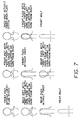
- the stitch types shown in Fig. 7 are represented by the terms head, kousoku, and nejiri among the parameters of the middle data described above.
- the CPU of the engineering workstation 140 stores expansively, for all the stitch positions constituting the fabric, the parameter values into the internal memory in the form of a table as shown in Figs. 23 and 24.
- stitch structure information such as the link start/end positions
- only those for specific stitch positions are stored into the memory.
- Sequence data (operation information of the first aspect of the present invention) describes the procedure for forming an objective fabric for the knitting operation of a general knitting machine.
- the sequence data includes the following elements:
- the sequence data is described in such a manner that the elements (a) - (f) in the sequence required for the knitting, are arranged.
- the sequence data is expressed by integers including the elements (a) - (f). The numerals and allocation of the individual operations will be described later.
- the sequence data is structured as follows: First, it has a space of several bytes as a head.
- the sequence data is formed by arranging each set of data in the knitting direction, the set of data corresponding to a row which is referred to as a course.
- One course data is provided with an identification name COURSE, and is represented by (the course number), (operation information in the course), and COURSEend (an end code of the data).
- the course number is an integer beginning with 1, and is incremented by 1 with each course.
- the operation information in the course includes the following elements which are arranged freely as needed.
- the knitting operation information is provided with an identification name AMI, and is represented by (a yarn number), (knitting direction data), (needle operation data), and AMIend (an end code).
- the knitting direction data takes one of the following:
- the needle operation is represented as (a needle number), (a knitting manner), and (a stitch length), and sets of these information for the necessary number of needles are described.
- the needle number is a numeral that is represented as follows, where n is the needle number. a front needle is indicated as n * 2-1, a back needle is indicated as n * 2.
- the knitting manner data is one of the following:
- the racking amount is expressed in 1/2 needle pitch. The sign thereof is negative for leftward racking.
- the stitch transfer operation data is represented as MEsrv (an identification name of a needle on the serving side), MErcv (an identification name of a needle on the receiving side), and MEend (an end code).
- the number of needles required on the serving and receiving sides are described for individual operations. Here, they must match to each other.
- the number used corresponds to the number of a needle in the knitting operation.
- the dropping action data is represented as HAstart (an identification name of a drop needle) and HAend (an end code).
- the number used corresponds to the number of a needle in the knitting operation.
- the set data of the encounter is represented as DEAI (an identification name of the encounter) and DEAIend (an end code).
- the encounter is either of the following:
- the pull-down tension setting data is represented as TEN (an identification name of pull-down tension) and TENend (an end code).
- the pull-down tension is indicated by an integer from 0 to 255.
- the correspondence between the pull-down tension setting data and the actual tension is determined by the controller of the knitting machine main unit.
- the tension setting is used for changing when the next code is appeared after the code is appeared once, or used before the knitting operation is made.
- sequence data groups are developed and stored on the internal memory of the engineering workstation 140 in the form of a table for each stitch position in the sequence conversion processing described below.
- Fig. 25 shows the preparation procedure of the knitting operation data.
- the sequence in which the stitches (more precisely, loop heads) are continuously formed, and their stitch positions are found for a yarn (a particular yarn number) among the design data groups stored in connection with the stitch positions. Then, parameters associated with the sequence data are retrieved from the design data at the stitch positions corresponding to the formation sequence, and the parameters are used to prepare the sequence data.
- the detected stitch positions have one-to-one correspondence with the positions where the knitting needles operate (that is, the positions for knitting, transferring, and the like), it can be converted to the knitting needles instructed to be driven.
- the CPU of the engineering workstation 140 performs the following search processing on the design data groups stored in the memory.
- the yarn number to be searched for is initially set to "1" (step S3010), and the design data is read beginning from the read start position of the memory (a loop processing consisting of steps S3020 - S3030 - S3040 - S3050 - S3030).
- the CPU detects in step S3040 that the link start information of yarn number "1" is included in the design data, the CPU transfers the procedure to step S3100 to retrieve the knitting manner data and the stitch length data from the read design data.
- the CPU reversely calculates the stitch position from the presently read address, and then sets the needle type data and the needle number (as well as the needle type) corresponding to the stitch position in the design data.
- the sequence data (knitting operation data) including a set of the needle numbers, the knitting manner data, and stitch length data is prepared, and are stored in the memory (steps S3100 - S3110).
- the CPU further calculates the next stitch position to be connected to the present stitch by using the information on the position and distance of the stitch to be formed next along the knitting direction of the yarn, and computes the read address of the memory corresponding to the calculation result in accordance with the link-related information in the design data which has been read. Then, the CPU reads the design data at that address (steps S3120 - S3130).
- step S3140 the CPU sequentially detects positions where stitches are to be continuously formed, that is, the knitting positions, forms the knitting operation data on the basis of the design data, and stores them in the memory.
- the CPU updates the yarn number to "2", and returns the procedure to step S3020 when the link end is detected (step S3140).
- the CPU stores the driving sequence of the knitting needles corresponding to the stitch formation sequence in the loop processing of steps S3100 - S3140.
- step S3020 When the above processing is completed for all the yarn numbers (step S3020), the sequence data prepared is registered on the floppy disk as a file by the operator's instruction (step S3300). Then, the CPU ends the execution of the present control procedure.
- the other parameter data of the sequence data can be prepared in the same procedure except for the case where the other parameter data is used in substitute for the knitting operation data, description of the preparation procedure of the other parameter data is omitted.
- f is an identification code indicating the front needle
- k is an identification code indicating the knitting manner (knitting operation)
- 30 is a numeral indicating the stitch length.
- the control data is based on the knitting schedule.
- the knitting schedule is composed of the basic operations of the knitting machine, which are arranged in the sequence required for knitting.
- the basic operations mainly comprise the knitting, racking, transferring, and tension changes, with some instructions to control the knitting schedule.
- Knitting here means one yarn-carrier operation, and a withdrawal operation also constitutes one knitting operation.
- the instructions and their parameters are described below.
- the knitting parameters are referred to first.
- the knitting parameters indicate the designation of a yarn carrier, a target value of the operation, start conditions, knitting ranges, a pull-down tension setting value, and the like.
- a cam pattern which varies depending on the stitch length and the yarn type
- a table storing these cam patterns is a cam shape designation table. This table allocates a predetermined cam number to each needle in the knitting range.
- the present embodiment can use 97 cam numbers. This includes one for mis-operation, 48 for knit and tuck operations each. Since the knit and tuck operations must be used as a pair, 48 types of cams (stitch length codes) of different stitch length and yarn type can be used.
- Cam index data indicates the types of the 48 common cams in a piece of the entire fabric.
- This ASCII file indicates the stitch length and yarn type for each stitch length code.
- the knitting machine main unit searches the database to convert into an actual cam pattern according to this data.
- the parameters identical to the knitting parameters are provided.
- the range of transfer needles is determined by the knitting parameter, and the needle corresponding to it is instructed as one of the receiving side, the serving side or the non-operation in accordance with the cam shape designation table.
- the end of knitting end is indicated by the knitting end instruction in the knitting schedule.
- conditions for starting knitting, history of the control data, and the like are also stored in the cam index data.
- each table name is provided with an identification name.
- Each file has a header comprising a unit size of its data, the number of data, a table identification number, and a table version number.
- the knitting machine parameter file attached to the knitting machine main unit is provided with another identification name so that it is distinguished from the control data file.
- the end of the data constituting the knitting schedule is indicated by an end code added at the end position of the data.
- the knitting schedule uses codes specifying the following knitting operations. These are a no-operation; a practice knitting operation; a racking (an argument of 1 corresponds to half the needle pitch, and indicates the rightward movement of the back bed when it is negative); a transferring of the stitch; a pull-down tension change (an argument is a tension code); a pull-down tension reset; a yarn catcher operation; a yarn cutter operation end; a knitting end; an original point search; a return to original point; a front/back down stitch code; and the like.
- This table stores data necessary for knitting in the form of parameters, except for data of individual needles for respective courses. In addition to the data associated with the knitting, it also stores the data associated with withdrawal of the yarn carrier and with transferring of the stitch. Contents of the data and parameters are as follows:
- the start condition is a continuous one.
- Conditions for a restart after an interrupt include the following:
- data associated with each needle is indicated in a predetermined number of bytes, and the data for one course is arranged in the sequence of courses.
- the number of bytes required for each course is determined by the number of the front and back knitting needles of the knitting parameter table.
- An end code is provided at the end of each course data. This is for facilitating the reading of the entire data in each course.
- the data described here are cam numbers, and the actual operation is specified by the cam index data.
- the cam numbers used in the knitting operation include 96 numbers from 0 to 95, for example, and the even numbers are for a knit operation whereas the odd numbers are for a tuck operation, which are used in pairs. Therefore, the number of combinations of a stitch length and a yarn type that can be actually used for one fabric is 48. These are the internal codes, and they are called as knit 0 - knit 47, and tuck 0 - tuck 47.
- the converted value is n * 2 for knit n, and n * 2+1 for tuck n. This number n is referred to as a stitch length number or a stitch length code.
- Values 128 - 249 indicate mis-operations, but only 128 is actually used. Values 250 - 255 are reserved for use in other control. For the transferring operation, 0 is allocated to the service side, 1 is allocated to the receive side, and 128 is allocated to the no-operation.
- the needles are assumed to be arranged in sequence as front and back. None is mentioned about a bed without performing knitting.
- the code appearing first is the operation code of the knitting start needle.
- the cam index data is valid for an entire fabric.
- the data file has no header. This data describes a stitch length and a yarn type for each stitch length code used in the cam shape designation table.
- This file has the original design data name as a comment. It also has data about the data number and the data version.
- the stitch length values and the yarn types used in this file are the very values set by the design data and the sequence data. Their meanings, however, are determined by the program that converts them to the actual cam shapes.
- the knitting machine main unit When the knitting machine main unit reads the cam index data to form cam shapes, they are converted to cam numbers at a same time for knit operation and tuck operation
- the above-described knitting schedule, knitting parameter table, cam shape designation table, and cam index data table which correspond to the type of knitting machine, are created by rearranging the knitting sequence of the entire fabric for individual yarns indicated by the sequence data to the knitting sequence for individual courses.
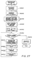
- control data conversion processing is started in the sequence of steps S130 - S170 - S4000. Details of the procedure of the conversion processing are shown in Fig. 27.
- the operator designates by the keyboard input unit 110 a sequence data file to be converted to the control data (step S4010).
- the CPU of the engineering workstation 140 reads the specified sequence data file from the floppy disk, and transfers it to the internal memory (steps S4010 - S4020).
- the CPU receives the machine type information of the knitting machine in the control data which has been prepared based on the input from the operator.
- the CPU loads the control data preparation program corresponding to the machine type information from the floppy disk on the internal memory, and thereafter performs calculation according to the data preparation program (step S4030).
- the CPU first stores in the internal memory the control data inherent in that knitting machine, which cannot be covered by the sequence data (step S4040).
- the sequence data in the internal memory which is arranged in the individual yarn numbers, is searched for over the range specified by the range information so that the parameters necessary for preparing the control data are extracted in accordance with the course number. More specifically, the course number "1" is set as the search object, and the parameters associated with the above control data are extracted from the range corresponding to the course number "1" and the first yarn number in the sequence data.
- the contents of the types of the parameters to be extracted and the relationship between the parameters of the control data and the sequence control data are defined in the program in the form of a numerical calculation equation or a logical operation equation.
- the CPU prepares the control data in accordance with the relationship previously defined in the program and by using the extracted parameters of the sequence data, and stores the result in the memory. After that, the same processing is performed repeatedly on the sequence data of. Next yarn number and the following yarn numbers in the course number.
- the CPU updates the course number, and prepares the control data in the sequence of the course number.
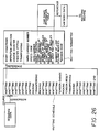
- the CPU registers in the file, according to the file instruction from the operator, these control data individually in the form of tables for the respective types as shown in Fig. 26.
- the thus file registered control data are read from the floppy disk by a transfer instruction of the operator from the keyboard input unit 110, and are transferred to the knitting machine control panel 320 shown in Fig. 2.
- the knitting machine carries out the knitting operation by the conventional method known in the art, according to the control data.
- step S120 in Fig. 4 the execution procedure of the CPU of the engineering workstation 140 proceeds to steps S130 - S170 - S5000 to display the control data.
- the CPU receives the identification name of the control data from the operator, reads the corresponding control data from the floppy disk, and displays it. It is also possible for the operator to watch the display screen, and input correction information from the keyboard input unit 110 to change the control data.
- the individual data are registered in a file on a floppy disk along with their identification names. Therefore, when the pattern and the stitch structure of the fabric are to be modified, the design data on the floppy disk is loaded on the engineering workstation. The operator causes the fabric to be displayed on the display screen, and adds corrections on necessary portions of the design data to prepare new fabric design data. Then, the design data is registered in the file on the floppy disk with a new identification name. Such a processing will reduce an amount of information to be inputted by the operator, thus simplifying the input operation.
- the sequence data be outputted to a printer for printing. Since the sequence data indicates the knitting procedure such as driving operations of the knitting needles and the bed, mis-setting will be reduced when the control data is set according to the knitting procedure.
- the present invention can implement the following
- the recording apparatus of U.S. Patent No. 4,608,642 prepares the control data for driving the knitting machine, when the operator inputs information indicating the knitting operation in the form of color codes rather than in the form of design information as in the present invention.
- the knit design system automatically prepares the information indicating the knitting operation, and the control data for driving the knitting machine, when the operator inputs the design information indicating a stitch structure and the like constituting the fabric. Since the operator can input data without considering the knitting sequence, the input operation can be simplified.
- the operator can learn the state of the finished fabric by visually confirming the fabric image displayed on the display unit, thereby eliminating the need for trial knitting as required in the prior art.
- the input design information is automatically converted to the operation information and the control information indicating the knitting procedure, the operator's burden for setting control information to various types of knitting machines is remarkably reduced.
Landscapes
- Engineering & Computer Science (AREA)
- Textile Engineering (AREA)
- Knitting Machines (AREA)
- Looms (AREA)
- Sewing Machines And Sewing (AREA)
Applications Claiming Priority (3)
| Application Number | Priority Date | Filing Date | Title |
|---|---|---|---|
| JP3236469A JP2656405B2 (ja) | 1991-09-17 | 1991-09-17 | ニットデザインシステムおよびその編成データの作成方法 |
| JP236469/91 | 1991-09-17 | ||
| PCT/JP1992/001182 WO1993006285A1 (fr) | 1991-09-17 | 1992-09-16 | Systeme de conception pour machine a tricoter et procede de production de donnees relatives au travail de tricotage |
Publications (3)
| Publication Number | Publication Date |
|---|---|
| EP0568700A1 true EP0568700A1 (de) | 1993-11-10 |
| EP0568700A4 EP0568700A4 (de) | 1994-03-02 |
| EP0568700B1 EP0568700B1 (de) | 1997-12-29 |
Family
ID=17001207
Family Applications (1)
| Application Number | Title | Priority Date | Filing Date |
|---|---|---|---|
| EP92920035A Expired - Lifetime EP0568700B1 (de) | 1991-09-17 | 1992-09-16 | Strickentwurfsystem und verfahren zur herstellung von strickdaten dafür |
Country Status (9)
| Country | Link |
|---|---|
| US (1) | US5388050A (de) |
| EP (1) | EP0568700B1 (de) |
| JP (1) | JP2656405B2 (de) |
| KR (1) | KR950000478B1 (de) |
| CN (1) | CN1075648C (de) |
| DE (1) | DE69223768T2 (de) |
| ES (1) | ES2110523T3 (de) |
| TW (1) | TW211594B (de) |
| WO (1) | WO1993006285A1 (de) |
Cited By (11)
| Publication number | Priority date | Publication date | Assignee | Title |
|---|---|---|---|---|
| EP0640707A1 (de) * | 1993-08-31 | 1995-03-01 | SHIMA SEIKI MFG., Ltd. | Strickentwurfsystem und Verfahren zum Entwerfen von gestrickten Stoffen |
| US5511394A (en) * | 1993-11-08 | 1996-04-30 | Shima Seiki Manufacturing, Ltd. | Method of producing knitted articles |
| EP0763615A1 (de) * | 1995-09-18 | 1997-03-19 | Shima Seiki Manufacturing Limited | Verfahren zum Entwurf eines rundgestrickten Artikels für eine Flachstrickmaschine |
| EP0768415A1 (de) * | 1995-10-12 | 1997-04-16 | Tsudakoma Kogyo Kabushiki Kaisha | Verfahren zur Anzeige von Strickwaren und Maschenstruktur |
| EP0768416A3 (de) * | 1995-10-16 | 1999-01-20 | Shima Seiki Manufacturing, Ltd. | Verfahren und Vorrichtung zum Entwurf eines Gestricks |
| US6845285B2 (en) | 2000-09-19 | 2005-01-18 | Shima Seiko Manufacturing Limited | Knitting support system and knitted product and knitting support server system |
| EP1445714A4 (de) * | 2001-10-05 | 2008-08-13 | Shima Seiki Mfg | Strickdesignverfahren und einrichtung |
| EP2955258A1 (de) * | 2014-06-13 | 2015-12-16 | Shima Seiki Mfg., Ltd. | Entwurfseinrichtung für strickwaren |
| WO2017041191A1 (de) | 2015-09-10 | 2017-03-16 | Uster Technologies Ag | Vorhersage des aussehens einer textilen fläche |
| EP3666102A1 (de) * | 2012-02-20 | 2020-06-17 | NIKE Innovate C.V. | Schuhwerk mit einer gestrickten komponente mit einer zunge |
| US11319651B2 (en) | 2012-02-20 | 2022-05-03 | Nike, Inc. | Article of footwear incorporating a knitted component with an integral knit tongue |
Families Citing this family (48)
| Publication number | Priority date | Publication date | Assignee | Title |
|---|---|---|---|---|
| JP2916990B2 (ja) * | 1993-08-31 | 1999-07-05 | 株式会社島精機製作所 | ニットペイントシステム及びニットペイント方法 |
| JPH09111619A (ja) * | 1995-10-13 | 1997-04-28 | Tsudakoma Corp | 編地と、その編成方法 |
| EP0781880B1 (de) * | 1995-12-28 | 2001-12-05 | Shima Seiki Manufacturing, Ltd. | Verfahren zum Abbinden von Strickwaren, Abgebundenes Gestrick und CAD-Vorrichtung dafür |
| US5987931A (en) * | 1996-11-21 | 1999-11-23 | Shima Seiki Manufacturing Ltd. | Knit design apparatus |
| DE19923802B4 (de) * | 1999-05-19 | 2012-09-13 | Sipra Patententwicklungs- Und Beteiligungsgesellschaft Mbh | Rundstrickmaschine zur Herstellung von Strickwaren mit wahlweise unterschiedlichen Eigenschaften und Verfahren zu ihrer Einstellung |
| WO2003032203A1 (en) * | 2001-10-05 | 2003-04-17 | Shima Seiki Manufacturing Limited | Knit design method and device |
| DE50113866D1 (de) * | 2001-10-06 | 2008-05-29 | Stoll & Co H | Verfahren und Einrichtung zum Entwurf von auf eineGestricken |
| US6782720B2 (en) * | 2002-01-30 | 2004-08-31 | Lakeland Industries | Unilayer fabric with reinforcing parts |
| US7127321B2 (en) * | 2002-08-30 | 2006-10-24 | Shima Seiki Manufacturing, Ltd. | Device for designing tubular knot fabric and method of designing |
| US6845284B2 (en) * | 2003-02-11 | 2005-01-18 | Sara Lee Corporation | Methods and systems for designing circularly knitted garments |
| DE602004013756D1 (de) * | 2003-03-31 | 2008-06-26 | Shima Seiki Mfg | Verfahren und vorrichtung für strickdesign |
| EP1616984B1 (de) * | 2003-04-04 | 2008-07-09 | Shima Seiki Manufacturing Limited | Verfahren und vorrichtung zum entwerfen einer maschenware |
| US7203566B2 (en) | 2003-04-15 | 2007-04-10 | Shima Seiki Manufacturing, Ltd. | Knit design method, apparatus therefor and program therefor |
| CN100519870C (zh) * | 2003-04-15 | 2009-07-29 | 株式会社岛精机制作所 | 编织设计方法及其装置 |
| JP4237601B2 (ja) | 2003-10-15 | 2009-03-11 | 株式会社島精機製作所 | ループシミュレーション装置とその方法並びにそのプログラム |
| JP4366321B2 (ja) * | 2005-02-18 | 2009-11-18 | 株式会社島精機製作所 | ニット製品のデザイン装置とデザイン方法、およびそのプログラム |
| EP1900862B1 (de) * | 2005-05-27 | 2014-09-03 | Shima Seiki Manufacturing., Ltd. | Strick- oder wirksimulationsvorrichtung, strick- oder wirksimulationsverfahren sowie programm dafür |
| CN101310061B (zh) * | 2005-11-17 | 2011-04-20 | 株式会社岛精机制作所 | 针织设计装置、针织设计方法 |
| BE1016943A6 (nl) * | 2006-01-13 | 2007-10-02 | Wiele Michel Van De Nv | Werkwijze voor het vermijden van mengcontouren in poolweefsels. |
| JP4890036B2 (ja) * | 2006-01-27 | 2012-03-07 | 株式会社カルタ | ニットデータ作成方法及び装置並びにプログラム |
| CN100350087C (zh) * | 2006-05-11 | 2007-11-21 | 李加林 | 一种具有不同特质的彩色提花织物的制作方法 |
| WO2009034910A1 (ja) * | 2007-09-10 | 2009-03-19 | Shima Seiki Manufacturing, Ltd. | ニットデザインでのデバッグ装置とデバッグ方法、デバッグプログラム |
| WO2009039668A1 (en) * | 2007-09-28 | 2009-04-02 | Smartpatterns Inc. | System and method for design of stitched objects |
| WO2009113282A1 (ja) * | 2008-03-12 | 2009-09-17 | 株式会社島精機製作所 | 編地のデザインシステム |
| CN102334752A (zh) * | 2010-07-28 | 2012-02-01 | 蔡佳真 | 内着物的制备方法及其结构 |
| DE102010053865B4 (de) * | 2010-12-08 | 2013-12-19 | H. Stoll Gmbh & Co. Kg | Verfahren zur Erstellung eines mit Strickdaten beschriebenen Gestrickmusters in mehreren Bearbeitungsstufen sowie Entwurfseinrichtung |
| US8726701B2 (en) * | 2011-03-17 | 2014-05-20 | The Moret Group | Method of making a knit apparel with a tie dyed appearance and an apparel made by the method |
| CN103382620B (zh) * | 2012-05-02 | 2015-01-21 | 杭州新强电脑控制技术有限公司 | 基于手套控制系统的单面提花编织方法 |
| US8529263B1 (en) * | 2012-07-13 | 2013-09-10 | Create2Thrive Inc. | System and method for interactive knitting functions |
| CN102864566B (zh) | 2012-09-29 | 2014-02-12 | 加宝利服装有限公司 | 织物制备方法、制备控制方法、制备控制装置和制备系统 |
| CN103034142B (zh) * | 2012-12-06 | 2015-09-30 | 杭州佳谷数控技术有限公司 | 一种自适应袜机控制方法及系统 |
| US10351982B2 (en) | 2014-09-15 | 2019-07-16 | Appalatch Outdoor Apparel Company | Systems, methods, and software for manufacturing a custom-knitted article |
| US11131045B2 (en) | 2014-09-15 | 2021-09-28 | Nimbly, Inc. | Systems, methods, and software for manufacturing a knitted article |
| US11461510B2 (en) * | 2018-05-08 | 2022-10-04 | Myntra Designs Private Limited | Generation system and method |
| EP3572570B1 (de) * | 2018-05-23 | 2022-05-18 | BSN-Jobst GmbH | Kompressionsartikel |
| US12421635B2 (en) | 2018-05-23 | 2025-09-23 | Essity Hygiene And Health Aktiebolag | Compression article |
| US11293124B2 (en) * | 2018-05-30 | 2022-04-05 | Nike, Inc. | Textile component production systems and methods |
| US11421355B2 (en) | 2018-06-15 | 2022-08-23 | Nike, Inc. | Tool for design and fabrication of knitted components |
| IL281141B2 (en) * | 2018-08-28 | 2025-03-01 | Uster Tech Ltd | Method and system for one-dimensional row-by-row inspection of fabrics |
| CN109371555B (zh) * | 2018-10-25 | 2020-07-03 | 银川瑞纳服饰有限公司 | 一种全成型针织服装程序文件制作流程的设计方法及装置 |
| KR102181025B1 (ko) * | 2019-04-08 | 2020-11-20 | 파이룽 머시너리 밀 코., 엘티디. | 자동으로 환편기를 교정하기 위한 직물 파일 배포 시스템 |
| US10988873B2 (en) * | 2019-04-08 | 2021-04-27 | Pai Lung Machinery Mill Co., Ltd. | Fabric file release system for automatically calibrating a circular knitting machine |
| JP6761505B1 (ja) * | 2019-04-11 | 2020-09-23 | 佰龍機械廠股▲ふん▼有限公司 | 丸編機の自動校正用の布地パターンデータ発行システム |
| EP3953512B1 (de) | 2019-04-12 | 2022-11-23 | Essity Hygiene and Health Aktiebolag | Gestrick und verfahren zur herstellung eines doppellagigen gestricks |
| JP7204589B2 (ja) * | 2019-06-18 | 2023-01-16 | 株式会社島精機製作所 | ニットデザインシステム |
| JP7655675B2 (ja) * | 2021-06-08 | 2025-04-02 | 株式会社島精機製作所 | 編地の編成方法、ニットデザインシステム、及び記憶媒体 |
| CN115221573B (zh) * | 2022-07-01 | 2025-12-05 | 福建睿能科技股份有限公司 | 织物的制版成型方法、电子终端及计算机可读存储介质 |
| CN116657316B (zh) * | 2023-04-19 | 2025-07-11 | 福建睿能科技股份有限公司 | 花型模块的绘制方法、针织横机和计算机可读存储介质 |
Family Cites Families (15)
| Publication number | Priority date | Publication date | Assignee | Title |
|---|---|---|---|---|
| JPS604634B2 (ja) * | 1974-04-09 | 1985-02-05 | カネボウ株式会社 | 柄解折装置 |
| JPS5493155A (en) * | 1977-12-25 | 1979-07-24 | Aisin Seiki | Hand knitting machine |
| JPS5536325A (en) * | 1978-08-29 | 1980-03-13 | Sharp Kk | Electronic control apparatus of knitting machine |
| DE2905240C2 (de) * | 1979-02-12 | 1985-09-19 | Universal Maschinenfabrik Dr. Rudolf Schieber Kg, 7081 Westhausen | Eingabegerät für eine Flachstrickmaschine mit elektronischer Steuerung |
| JPS5729647A (en) * | 1980-07-28 | 1982-02-17 | Brother Ind Ltd | Knitting apparatus for pattern knitting of hand knitting machine |
| FR2513669B1 (fr) * | 1981-09-28 | 1986-04-25 | Superba Sa | Machine a tricoter programmable |
| US4527402A (en) * | 1982-09-29 | 1985-07-09 | Rampon Products, Inc. | Program-controlled knitting machine, method and products thereof |
| JPS6071748A (ja) * | 1983-09-27 | 1985-04-23 | 株式会社島アイデア・センタ− | 柄情報の記録装置 |
| JP2888484B2 (ja) * | 1985-07-30 | 1999-05-10 | オプテイカル ストレツジ インターナシヨナル−ユーエス | 記録キャリア及び光データ読み書き装置 |
| US4768357A (en) * | 1986-02-13 | 1988-09-06 | Asahi Kasei Kogyo Kabushiki Kaisha | Method for knitting a flat knitted fabric, a flat knitting machine and a novel flat knitted fabric knitted by said flat knitting machine |
| DE3630828A1 (de) * | 1986-09-10 | 1988-03-24 | Stoll & Co H | Einrichtung zum darstellen und aufbereiten von mittels einer flachstrickmaschine herzustellenden strickmustern |
| JPS63120166A (ja) * | 1986-11-04 | 1988-05-24 | 花菱縫製株式会社 | 型片配列装置 |
| JPS6445856A (en) * | 1987-08-11 | 1989-02-20 | Brother Ind Ltd | Method for combining patterns due to pattern input apparatus of knitting machine |
| EP0356540A1 (de) * | 1988-08-30 | 1990-03-07 | Iam - Institut Für Angewandte Mikroelektronik Gmbh | Verfahren und Vorrichtung zur Bildung von Textilmustern mit Effektgarnen auf einem Wiedergabegerät |
| JPH03143472A (ja) * | 1989-10-31 | 1991-06-19 | Juki Corp | ミシン装置 |
-
1991
- 1991-09-17 JP JP3236469A patent/JP2656405B2/ja not_active Expired - Fee Related
-
1992
- 1992-09-16 CN CN92110717A patent/CN1075648C/zh not_active Expired - Fee Related
- 1992-09-16 EP EP92920035A patent/EP0568700B1/de not_active Expired - Lifetime
- 1992-09-16 KR KR1019930701455A patent/KR950000478B1/ko not_active Expired - Fee Related
- 1992-09-16 ES ES92920035T patent/ES2110523T3/es not_active Expired - Lifetime
- 1992-09-16 US US08/050,300 patent/US5388050A/en not_active Expired - Lifetime
- 1992-09-16 DE DE69223768T patent/DE69223768T2/de not_active Expired - Lifetime
- 1992-09-16 WO PCT/JP1992/001182 patent/WO1993006285A1/ja not_active Ceased
- 1992-10-01 TW TW081107824A patent/TW211594B/zh active
Cited By (17)
| Publication number | Priority date | Publication date | Assignee | Title |
|---|---|---|---|---|
| EP0640707A1 (de) * | 1993-08-31 | 1995-03-01 | SHIMA SEIKI MFG., Ltd. | Strickentwurfsystem und Verfahren zum Entwerfen von gestrickten Stoffen |
| EP0853153A3 (de) * | 1993-08-31 | 1998-10-21 | Shima Seiki Manufacturing, Ltd. | Strickenentwurfsystem und Verfahren zum Entwerfen von gestrickten Stoffen |
| EP0853154A3 (de) * | 1993-08-31 | 1998-10-21 | Shima Seiki Manufacturing, Ltd. | Strickentwurfsystem und Verfahren zum Entwerfen von gestrickten Stoffen |
| US5511394A (en) * | 1993-11-08 | 1996-04-30 | Shima Seiki Manufacturing, Ltd. | Method of producing knitted articles |
| EP0763615A1 (de) * | 1995-09-18 | 1997-03-19 | Shima Seiki Manufacturing Limited | Verfahren zum Entwurf eines rundgestrickten Artikels für eine Flachstrickmaschine |
| EP0768415A1 (de) * | 1995-10-12 | 1997-04-16 | Tsudakoma Kogyo Kabushiki Kaisha | Verfahren zur Anzeige von Strickwaren und Maschenstruktur |
| EP0768416A3 (de) * | 1995-10-16 | 1999-01-20 | Shima Seiki Manufacturing, Ltd. | Verfahren und Vorrichtung zum Entwurf eines Gestricks |
| US6845285B2 (en) | 2000-09-19 | 2005-01-18 | Shima Seiko Manufacturing Limited | Knitting support system and knitted product and knitting support server system |
| EP1445714A4 (de) * | 2001-10-05 | 2008-08-13 | Shima Seiki Mfg | Strickdesignverfahren und einrichtung |
| EP3666102A1 (de) * | 2012-02-20 | 2020-06-17 | NIKE Innovate C.V. | Schuhwerk mit einer gestrickten komponente mit einer zunge |
| US11155945B2 (en) | 2012-02-20 | 2021-10-26 | Nike, Inc. | Article of footwear incorporating a knitted component with a tongue |
| US11319651B2 (en) | 2012-02-20 | 2022-05-03 | Nike, Inc. | Article of footwear incorporating a knitted component with an integral knit tongue |
| US11566354B2 (en) | 2012-02-20 | 2023-01-31 | Nike, Inc. | Article of footwear incorporating a knitted component with a tongue |
| US12264422B2 (en) | 2012-02-20 | 2025-04-01 | Nike, Inc. | Article of footwear incorporating a knitted component with an integral knit tongue |
| US12486600B2 (en) | 2012-02-20 | 2025-12-02 | Nike, Inc. | Article of footwear incorporating a knitted component with a tongue |
| EP2955258A1 (de) * | 2014-06-13 | 2015-12-16 | Shima Seiki Mfg., Ltd. | Entwurfseinrichtung für strickwaren |
| WO2017041191A1 (de) | 2015-09-10 | 2017-03-16 | Uster Technologies Ag | Vorhersage des aussehens einer textilen fläche |
Also Published As
| Publication number | Publication date |
|---|---|
| WO1993006285A1 (fr) | 1993-04-01 |
| TW211594B (de) | 1993-08-21 |
| DE69223768T2 (de) | 1998-08-06 |
| JP2656405B2 (ja) | 1997-09-24 |
| EP0568700B1 (de) | 1997-12-29 |
| JPH0578960A (ja) | 1993-03-30 |
| KR930702571A (ko) | 1993-09-09 |
| KR950000478B1 (ko) | 1995-01-20 |
| US5388050A (en) | 1995-02-07 |
| DE69223768D1 (de) | 1998-02-05 |
| CN1075648C (zh) | 2001-11-28 |
| CN1070752A (zh) | 1993-04-07 |
| ES2110523T3 (es) | 1998-02-16 |
| EP0568700A4 (de) | 1994-03-02 |
Similar Documents
| Publication | Publication Date | Title |
|---|---|---|
| EP0568700B1 (de) | Strickentwurfsystem und verfahren zur herstellung von strickdaten dafür | |
| US6611730B1 (en) | Device and method of designing knit products to be manufactured on a knitting machine | |
| EP0640707B1 (de) | Strickentwurfsystem und Verfahren zum Entwerfen von gestrickten Stoffen | |
| EP0763615B1 (de) | Verfahren zum Entwurf eines rundgestrickten Artikels für eine Flachstrickmaschine und Vorrichtung zur Durchführung des Verfahrens | |
| US6895787B2 (en) | Knit design method and apparatus | |
| KR20040041671A (ko) | 니트 디자인 방법 및 장치 | |
| KR100706649B1 (ko) | 니트 디자인 시스템 | |
| EP1538249A1 (de) | Vorrichtung zum entwerfen von schlauff rmiger maschenware und entwurfsverfahren | |
| EP2975165B1 (de) | Verfahren zum stricken eines zopfmusters, designsystem für strickware und speichermedium | |
| EP1652983B1 (de) | Verfahren und vorrichtung zum maschenwarenentwurf | |
| EP1900862B1 (de) | Strick- oder wirksimulationsvorrichtung, strick- oder wirksimulationsverfahren sowie programm dafür | |
| EP1614787B1 (de) | Verfahren und vorrichtung für strickdesign | |
| EP2189560B1 (de) | Vorrichtung und verfahren zur fehlerentfernung bei einem strickentwurf und fehlersuchprogramm | |
| EP1849902B1 (de) | Designvorrichtung und strickverfahren | |
| EP1956129B1 (de) | Vorrichtung zum entwurf einer maschenware sowie verfahren zum entwurf einer maschenware und entsprechendes computerprogramm | |
| JP7204583B2 (ja) | ニットデザインシステム | |
| EP2492384B1 (de) | Strickdesignvorrichtung und Strickdesignverfahren | |
| EP1950676B1 (de) | Grenzmuster-entwurfseinrichtung, entwurfsverfahren und entwurfsprogramm | |
| CN111501186B (zh) | 针织物的设计系统 | |
| JPH06297302A (ja) | 作業工程編成装置 | |
| EP2955258B1 (de) | Entwurfseinrichtung für strickwaren | |
| JPH09158011A (ja) | 編み地設計システムにおけるリンキングデータ表示方法 | |
| JPH0731764A (ja) | 刺繍データ作成装置 | |
| JPS6011146B2 (ja) | 編機 | |
| JPS633061B2 (de) |
Legal Events
| Date | Code | Title | Description |
|---|---|---|---|
| PUAI | Public reference made under article 153(3) epc to a published international application that has entered the european phase |
Free format text: ORIGINAL CODE: 0009012 |
|
| 17P | Request for examination filed |
Effective date: 19930514 |
|
| AK | Designated contracting states |
Kind code of ref document: A1 Designated state(s): CH DE ES FR GB IT LI |
|
| A4 | Supplementary search report drawn up and despatched |
Effective date: 19940112 |
|
| AK | Designated contracting states |
Kind code of ref document: A4 Designated state(s): CH DE ES FR GB IT LI |
|
| 17Q | First examination report despatched |
Effective date: 19951229 |
|
| GRAG | Despatch of communication of intention to grant |
Free format text: ORIGINAL CODE: EPIDOS AGRA |
|
| GRAG | Despatch of communication of intention to grant |
Free format text: ORIGINAL CODE: EPIDOS AGRA |
|
| GRAH | Despatch of communication of intention to grant a patent |
Free format text: ORIGINAL CODE: EPIDOS IGRA |
|
| GRAH | Despatch of communication of intention to grant a patent |
Free format text: ORIGINAL CODE: EPIDOS IGRA |
|
| GRAA | (expected) grant |
Free format text: ORIGINAL CODE: 0009210 |
|
| AK | Designated contracting states |
Kind code of ref document: B1 Designated state(s): CH DE ES FR GB IT LI |
|
| REG | Reference to a national code |
Ref country code: CH Ref legal event code: EP |
|
| REF | Corresponds to: |
Ref document number: 69223768 Country of ref document: DE Date of ref document: 19980205 |
|
| REG | Reference to a national code |
Ref country code: ES Ref legal event code: FG2A Ref document number: 2110523 Country of ref document: ES Kind code of ref document: T3 |
|
| ET | Fr: translation filed | ||
| ITF | It: translation for a ep patent filed | ||
| REG | Reference to a national code |
Ref country code: CH Ref legal event code: NV Representative=s name: BOVARD AG PATENTANWAELTE |
|
| PLBE | No opposition filed within time limit |
Free format text: ORIGINAL CODE: 0009261 |
|
| STAA | Information on the status of an ep patent application or granted ep patent |
Free format text: STATUS: NO OPPOSITION FILED WITHIN TIME LIMIT |
|
| 26N | No opposition filed | ||
| REG | Reference to a national code |
Ref country code: GB Ref legal event code: IF02 |
|
| PGFP | Annual fee paid to national office [announced via postgrant information from national office to epo] |
Ref country code: ES Payment date: 20100923 Year of fee payment: 19 Ref country code: CH Payment date: 20100914 Year of fee payment: 19 |
|
| PGFP | Annual fee paid to national office [announced via postgrant information from national office to epo] |
Ref country code: IT Payment date: 20100918 Year of fee payment: 19 Ref country code: FR Payment date: 20100921 Year of fee payment: 19 |
|
| PGFP | Annual fee paid to national office [announced via postgrant information from national office to epo] |
Ref country code: GB Payment date: 20100916 Year of fee payment: 19 |
|
| PGFP | Annual fee paid to national office [announced via postgrant information from national office to epo] |
Ref country code: DE Payment date: 20100908 Year of fee payment: 19 |
|
| REG | Reference to a national code |
Ref country code: CH Ref legal event code: PFA Owner name: ASAHI KASEI KOGYO KABUSHIKI KAISHA Free format text: ASAHI KASEI KOGYO KABUSHIKI KAISHA#2-6, DOJIMAHAMA 1-CHOME KITA-KU#OSAKA-SHI OSAKA 530 (JP) -TRANSFER TO- ASAHI KASEI KOGYO KABUSHIKI KAISHA#2-6, DOJIMAHAMA 1-CHOME KITA-KU#OSAKA-SHI OSAKA 530 (JP) |
|
| REG | Reference to a national code |
Ref country code: CH Ref legal event code: PL |
|
| GBPC | Gb: european patent ceased through non-payment of renewal fee |
Effective date: 20110916 |
|
| PG25 | Lapsed in a contracting state [announced via postgrant information from national office to epo] |
Ref country code: IT Free format text: LAPSE BECAUSE OF NON-PAYMENT OF DUE FEES Effective date: 20110916 |
|
| REG | Reference to a national code |
Ref country code: FR Ref legal event code: ST Effective date: 20120531 |
|
| REG | Reference to a national code |
Ref country code: DE Ref legal event code: R119 Ref document number: 69223768 Country of ref document: DE Effective date: 20120403 |
|
| PG25 | Lapsed in a contracting state [announced via postgrant information from national office to epo] |
Ref country code: CH Free format text: LAPSE BECAUSE OF NON-PAYMENT OF DUE FEES Effective date: 20110930 Ref country code: DE Free format text: LAPSE BECAUSE OF NON-PAYMENT OF DUE FEES Effective date: 20120403 Ref country code: LI Free format text: LAPSE BECAUSE OF NON-PAYMENT OF DUE FEES Effective date: 20110930 |
|
| PG25 | Lapsed in a contracting state [announced via postgrant information from national office to epo] |
Ref country code: FR Free format text: LAPSE BECAUSE OF NON-PAYMENT OF DUE FEES Effective date: 20110930 Ref country code: GB Free format text: LAPSE BECAUSE OF NON-PAYMENT OF DUE FEES Effective date: 20110916 |
|
| REG | Reference to a national code |
Ref country code: ES Ref legal event code: FD2A Effective date: 20130418 |
|
| PG25 | Lapsed in a contracting state [announced via postgrant information from national office to epo] |
Ref country code: ES Free format text: LAPSE BECAUSE OF NON-PAYMENT OF DUE FEES Effective date: 20110917 |