EP0568975A1 - Zuführvorrichtung für Bogendruckmaschine - Google Patents
Zuführvorrichtung für Bogendruckmaschine Download PDFInfo
- Publication number
- EP0568975A1 EP0568975A1 EP93107212A EP93107212A EP0568975A1 EP 0568975 A1 EP0568975 A1 EP 0568975A1 EP 93107212 A EP93107212 A EP 93107212A EP 93107212 A EP93107212 A EP 93107212A EP 0568975 A1 EP0568975 A1 EP 0568975A1
- Authority
- EP
- European Patent Office
- Prior art keywords
- paper
- suction port
- suction
- port member
- paper sheet
- Prior art date
- Legal status (The legal status is an assumption and is not a legal conclusion. Google has not performed a legal analysis and makes no representation as to the accuracy of the status listed.)
- Granted
Links
Images


Classifications
-
- B—PERFORMING OPERATIONS; TRANSPORTING
- B65—CONVEYING; PACKING; STORING; HANDLING THIN OR FILAMENTARY MATERIAL
- B65H—HANDLING THIN OR FILAMENTARY MATERIAL, e.g. SHEETS, WEBS, CABLES
- B65H3/00—Separating articles from piles
- B65H3/08—Separating articles from piles using pneumatic force
- B65H3/0808—Suction grippers
- B65H3/0816—Suction grippers separating from the top of pile
- B65H3/0833—Suction grippers separating from the top of pile and acting on the front part of the articles relatively to the final separating direction
Definitions
- the present invention relates to a paper feed apparatus for a sheet-fed press, which draws a paper sheet stacked on the paper stack plate of a paper stack table, grips the leading end portion of the paper sheet with a paper convey member, and feeds the paper sheet onto a feeder board to perform printing.
- a paper feed apparatus provided to a sheet-fed press has a paper stack table for supporting a paper stack plate on which paper sheets are stacked.
- a plate-like feeder board is inclinedly supported in front of the paper stack table such that its front portion is lower than its rear portion.
- a suction port member that can move vertically and back and forward is provided above the stacked paper sheet.
- a paper feed roller to be rotated by a driving unit and a paper feed roll opposing the upper circumferential surface of the paper feed roller are provided between the paper stack table and the feeder board.
- paper sheets stacked on the paper stack plate on the paper stack table are drawn one by one from the highest one by the suction port member, and the drawn paper sheet is moved forward.
- the moved paper sheet is gripped by the paper feed roller and the paper feed roll at its leading end portion, and is fed onto the feeder board as the paper feed roller and the paper feed roll are rotated.
- Japanese Patent Publication No. 45-12928 discloses an arrangement in which the leading end portion of a paper sheet is drawn by a suction port member.
- This arrangement will be described. More specifically, this paper feed apparatus has a feed roller, a guide arm, a suction port member, and a guide plate.
- the feed roller is axially supported above the leading end portion of the stacked paper sheet and rotated by a motor.
- the guide arm is supported by a link mechanism and moved forward and backward in the horizontal direction so as to enter from the front side to bring the roll at its distal end portion into contact with the lower circumferential surface of the feed roller and to be retreated forward from the entered state.
- the suction port member is supported by the link mechanism and moved in the vertical direction with respect to the leading end face of the paper sheet to draw the paper sheet.
- the guide plate is supported above the reciprocal path of the guide arm.
- a paper feed roller and a paper feed roll that oppose each other in the vertical direction, and a feeder board, three of which are similar to those described above, are provided in front of the guide plate.
- the suction port member is moved downward from the upper stop position, draws the leading end portion of the paper sheet, and is then moved upward to the upper stop position, and releases the paper sheet.
- the guide arm enters below the feed roller, and the roll at the distal end portion of the guide arm is brought into contact with the lower circumferential surface of the feed roller.
- the released paper sheet is clamped by the feed roller and the roll.
- the paper sheet is fed to a portion below the suction port member by the rotation of the feed roller and the roll.
- the paper sheet which is being quickly moved forward and the suction port member may undesirably interfere with each other. It is, however, difficult to set the timing so as not to cause this interference.
- high-speed printing cannot be achieved.
- a paper feed apparatus for a sheet-fed press comprising a paper stack unit for stacking paper sheets on a paper stack plate thereof, a suction port member for drawing a leading end portion of the paper sheet stacked on the paper stack unit, driving means for moving the suction port member vertically between a suction position and an upper position and back and forth between the suction position and a retreat position, and paper convey means, disposed within a forward path of the suction port member, for drawing the paper sheet conveyed by the suction port member and feeding the paper sheet onto a feeder board.
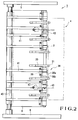
- Figs. 1 to 3 show a paper feed apparatus for a sheet-fed press according to an embodiment of the present invention.
- a paper feed apparatus 1 has a paper stack unit 4 comprising a paper stack table (not shown), a front gauge 3, and the like.
- the paper stack table is suspended by a vertical chain to be vertically movable.
- the front gauge 3 abuts against the leading ends of paper sheets 2 stacked on the paper stack table through a paper stack plate, thereby aligning the paper sheets.
- a plate-like feeder board 6 is provided in front of the upper end portion of the paper stack unit 4.
- the feeder board 6 is inclined toward its front end, and the two end portions of the feeder board 6 are supported by frames 5.
- a cam mechanism 50 serving as a driving means to move suction ports 31 (to be described later) in the vertical direction and the forward-and-backward direction is provided below the feeder board 6.
- the cam mechanism 50 has a cam shaft 7 located below the feeder board 6, having two end portions axially supported by the frames 5, and driven by a motor.
- a pair of first back-and-forth driving cams 8 each having a cam surface comprising large- and small-diameter portions 8a and 8b, a pair of second back-and-forth driving cams 9 each having a cam surface comprising large- and small-diameter portions 9a and 9b, and a pair of vertical driving cams 10 each having a cam surface comprising large- and small-diameter portions 10a and 10b are fixed on the cam shaft 7 to be close to the corresponding frames 5.
- Lever shafts 11 and 12 with rolls are pivotally axially supported by the frames 5 on the two sides to extend in front of and behind the cam shaft 7.
- Levers 13 and 14 with rolls are fixed to the lever shafts 11 and 12, respectively.
- a lever shaft 17 extends above the cam shaft 7 as it is pivotally axially supported by the frames 5 on the two sides.
- Levers 18 are fixed on the lever shaft 17 by split clamping.
- the free end portions of the levers 18 is coupled to the free end portions of the lever 14 by coupling levers 19 each having the two ends pivotally mounted on the free and portions of the corresponding lever 18 and the lever 14.
- the other end of each rod 20 having one end pivotally mounted on the corresponding lever 18 is slidably inserted in the rod hole of a stud 21 pivotally mounted on the free end portion of the corresponding lever 13.
- Belleville springs 23 for pressing the rolls 15 and 16 against the back-and-forth driving cams 8 and 9 on the two sides are interposed between the studs 21 and nuts 22 threadably engaged with the distal end portions of the rods 20.
- Reference numeral 24 denotes a tubular lever shaft 24 with a roll pivotally axially supported on the frames 5 on the two sides to be in parallel to the lever shaft 17.
- Levers 25 with rolls are fixed on the lever shaft 24 by split clamping.
- Rolls 26 pivotally mounted on the free end portions of the levers 25 oppose the cam surfaces of the vertical driving cams 10. The rolls 26 are pressed against the cam surfaces of the vertical driving cams 10 by compression coil springs 28 interposed between the levers 25 and studs 27 of the frames 5.
- a plurality of operation levers 29 are fixed on the lever shaft 17 by split clamping in an aligned state.
- An L-shaped suction port arm 30 is pivotally mounted on the free end portion of each operation lever 29, and a suction port member 31 is fixed on one free end portion of each suction port arm 30.
- the lever shaft 17 has a tubular shape, and its inner hole is connected to a suction air source through a hose (not shown).
- the inner hole of the lever shaft 17 and air paths 30a formed in the suction port arms 30 are connected by flexible hoses 32.
- the air paths 30a of the suction port arms 30 are open in the lower end suction surfaces of the suction port members 31.
- Cam levers 33 having arcuated cam surfaces 33a on their upper surfaces are fixed on the lever shafts 24 by split clamping.
- a roll 34 pivotally mounted on the other free end portion of each suction port arm 30 opposes the cam surface 33a of the corresponding cam lever 33.
- Tension springs 37 for bringing the corresponding roll 34 into contact with the cam surface 33a extend between the two end portions of a pivot shaft 35 on which this roll 34 is pivotally mounted, and spring grips 36 provided to the pivotal support portion of each operation lever 29.
- a plurality of paper feed rollers 38 serving as a paper convey means and comprising a plurality of large-diameter roller portions 38a and a plurality of small-diameter end shafts 38b are axially rotatably supported by U-shaped holders 39 shown in Fig. 2.
- Paper feed tapes 41 extend between the paper feed rollers 38 and a tape roller 40 axially extending in front of the distal end of the feeder board 6. The paper feed rollers 38 are rotated by the tape roller 40 through the paper feed tapes 41.
- paper feed rolls 43 axially rotatably supported by holders 42 of the frames 5 are disposed above the two paper feed rollers 38, in this embodiment, of the plurality of paper feed rollers 38, and the paper feed rolls 43 are pressed against the circumferential surfaces of the paper feed rollers 38.
- the paper sheet 2, which is drawn by the suction port members 31 and being moved forward, is released while it is moving forward, gripped by the paper feed rollers 38 and the paper feed rolls 43, fed onto the feeder board 6, and conveyed by the paper feed tapes 41 and rollers and brushes (not shown).
- the operation of the paper feed apparatus having the above arrangement will be described.
- the paper sheets 2 are stacked on the paper stack plate of the paper stack unit, and the cam shaft 7 is rotated clockwise to start the printing operation.
- the large-diameter portions 9a of the second back-and-forth driving cams 9 are brought into contact with the rolls 15 and the small-diameter portions 8b of the first back-and-forth driving cams 8 are brought into contact with the rolls 16, so that the suction port members 31 of the suction port arms 30 located at the retreat position 31c in Fig. 1 are moved in the direction of the arrow C through the rods 20, the levers 18, and the operation levers 29.
- the large-diameter portions 8a of the first back-and-forth driving cams 8 are brought into contact with the rolls 16, and the small-diameter portions 9b of the second back-and-forth driving cams 9 are brought into contact with the rolls 15, so that the levers 14 and 15 are pivoted clockwise in Fig. 1 about the lever shafts 11 and 12, respectively.
- the levers 18 are pivoted counterclockwise through the rods 20, and the operation levers 29 are also pivoted counterclockwise, thereby moving the suction port arms 30 in the direction of the arrow B to return the suction port members 31 to the retreat position 31c.
- Fig. 4 is a side view showing a portion near a paper convey member of a paper feed apparatus according to another embodiment of the present invention. Members having the same arrangements as those in Fig. 1 are denoted by the same reference numerals, and a detailed description thereof will be omitted.
- suction wheels 60 are used to serve as the paper convey member that grips a paper sheet 2, drawn by suction port members 31 and moved, and feeds the paper sheet 2 onto a feeder board 6.
- the plurality of suction wheels 60 are disposed parallel to each other at positions, between the front end of the feeder board 6 and a front gauge 3, corresponding to the paper feed rollers 38.
- the suction wheels 60 are rotated by a motor in a direction indicated by an arrow in Fig. 4.
- the paper sheet 2 drawn by the suction port members 31 and moved is released from the suction port members 31 above the suction wheels 60, is drawn by the circumferential surfaces of the suction wheels 60 by the operation of the suction air to the suction holes 60a, is fed onto the feeder board 6, and is conveyed by the paper feed tapes 41.
- the paper feed rollers 38 or suction wheels 60, and the paper feed tapes 41 provided to them are indicated as the paper convey means.
- the paper convey means may include only the paper feed tapes 41 or paper feed rollers 38.
- the cam mechanism is indicated as the driving means for moving the suction port members 31 in the vertical direction and the forward-and-backward direction.
- the driving means is not limited to the cam mechanism, and even a driving means other than the cam mechanism can provide the same effect.
- the timing to avoid paper interference can be easily set to enable a stable paper feed operation. Since the suction port members draw the leading end portion of the paper sheet and feed out the paper sheet, the paper sheet can be smoothly fed to further stabilize the paper feed operation, and the waste paper is decreased. Since a sucker box which is conventionally used is not needed, the operability of the paper stacking operation and the like is improved.
Landscapes
- Engineering & Computer Science (AREA)
- Mechanical Engineering (AREA)
- Sheets, Magazines, And Separation Thereof (AREA)
- Impression-Transfer Materials And Handling Thereof (AREA)
- Advancing Webs (AREA)
- Sewing Machines And Sewing (AREA)
- Feeding Of Articles By Means Other Than Belts Or Rollers (AREA)
Applications Claiming Priority (2)
| Application Number | Priority Date | Filing Date | Title |
|---|---|---|---|
| JP142067/92 | 1992-05-08 | ||
| JP4142067A JPH05310335A (ja) | 1992-05-08 | 1992-05-08 | 枚葉印刷機の給紙装置 |
Publications (2)
| Publication Number | Publication Date |
|---|---|
| EP0568975A1 true EP0568975A1 (de) | 1993-11-10 |
| EP0568975B1 EP0568975B1 (de) | 1997-04-09 |
Family
ID=15306663
Family Applications (1)
| Application Number | Title | Priority Date | Filing Date |
|---|---|---|---|
| EP93107212A Expired - Lifetime EP0568975B1 (de) | 1992-05-08 | 1993-05-04 | Zuführvorrichtung für Bogendruckmaschine |
Country Status (5)
| Country | Link |
|---|---|
| US (1) | US5342035A (de) |
| EP (1) | EP0568975B1 (de) |
| JP (1) | JPH05310335A (de) |
| AT (1) | ATE151380T1 (de) |
| DE (1) | DE69309531T2 (de) |
Families Citing this family (8)
| Publication number | Priority date | Publication date | Assignee | Title |
|---|---|---|---|---|
| US20060030387A1 (en) * | 2004-08-09 | 2006-02-09 | Jackson Kathleen N | Payline system for multiline slot play using an erasing/exposure feature |
| US9214067B2 (en) | 2012-09-06 | 2015-12-15 | Igt | Gaming system and method for providing a streaming symbols game |
| US9028318B2 (en) | 2012-09-27 | 2015-05-12 | Igt | Gaming system and method for providing a game which populates symbols along a path |
| US9039512B2 (en) | 2012-09-27 | 2015-05-26 | Igt | Gaming system and method for providing a game which populates symbols along a path |
| US8992301B2 (en) | 2012-09-27 | 2015-03-31 | Igt | Gaming system and method for providing a game which populates symbols along a path |
| US8784191B1 (en) | 2013-03-07 | 2014-07-22 | Igt | Gaming system and method for providing a symbol elimination game |
| US8851979B2 (en) | 2013-03-07 | 2014-10-07 | Igt | Gaming system and method for providing a symbol elimination game |
| US10186106B2 (en) | 2016-09-21 | 2019-01-22 | Igt | Gaming system and method for determining awards based on interacting symbols |
Citations (5)
| Publication number | Priority date | Publication date | Assignee | Title |
|---|---|---|---|---|
| US1920388A (en) * | 1930-11-19 | 1933-08-01 | Harris Seybold Potter Co | Sheet-feeder |
| US2185652A (en) * | 1937-09-18 | 1940-01-02 | Spiess Georg | Sheet separator |
| US2201604A (en) * | 1937-08-26 | 1940-05-21 | Backhouse Headley Townsend | Sheet feeder |
| FR2254435A2 (de) * | 1973-12-14 | 1975-07-11 | Heidelberger Druckmasch Ag | |
| DE2500222A1 (de) * | 1974-08-23 | 1976-03-11 | Sakurai Ltd | Vorrichtung fuer die parallele einfuehrung von zu bedruckendem material in eine druckmaschine |
Family Cites Families (7)
| Publication number | Priority date | Publication date | Assignee | Title |
|---|---|---|---|---|
| US1853781A (en) * | 1928-08-13 | 1932-04-12 | Stokes & Smith Co | Method and apparatus for sheet feeding |
| US2084065A (en) * | 1932-07-20 | 1937-06-15 | Arthur Wormser | Sheet feeding machine |
| US2693957A (en) * | 1951-06-19 | 1954-11-09 | Ormonde P Welsh | Envelope machine |
| US3261601A (en) * | 1964-08-27 | 1966-07-19 | Mabeg Maschb G M B H Nachf Hen | Sheet pick-up and conveying device |
| DE2637218C2 (de) * | 1976-08-18 | 1980-10-02 | Georg Spiess Gmbh, 8906 Gersthofen | Bogenanleger |
| JPH023126A (ja) * | 1987-11-26 | 1990-01-08 | Ricoh Co Ltd | 情報記録媒体 |
| JPH0738286Y2 (ja) * | 1989-09-12 | 1995-08-30 | ホリゾン・インターナショナル株式会社 | 丁合機用給紙装置 |
-
1992
- 1992-05-08 JP JP4142067A patent/JPH05310335A/ja active Pending
-
1993
- 1993-04-27 US US08/053,145 patent/US5342035A/en not_active Expired - Lifetime
- 1993-05-04 DE DE69309531T patent/DE69309531T2/de not_active Expired - Fee Related
- 1993-05-04 AT AT93107212T patent/ATE151380T1/de not_active IP Right Cessation
- 1993-05-04 EP EP93107212A patent/EP0568975B1/de not_active Expired - Lifetime
Patent Citations (5)
| Publication number | Priority date | Publication date | Assignee | Title |
|---|---|---|---|---|
| US1920388A (en) * | 1930-11-19 | 1933-08-01 | Harris Seybold Potter Co | Sheet-feeder |
| US2201604A (en) * | 1937-08-26 | 1940-05-21 | Backhouse Headley Townsend | Sheet feeder |
| US2185652A (en) * | 1937-09-18 | 1940-01-02 | Spiess Georg | Sheet separator |
| FR2254435A2 (de) * | 1973-12-14 | 1975-07-11 | Heidelberger Druckmasch Ag | |
| DE2500222A1 (de) * | 1974-08-23 | 1976-03-11 | Sakurai Ltd | Vorrichtung fuer die parallele einfuehrung von zu bedruckendem material in eine druckmaschine |
Also Published As
| Publication number | Publication date |
|---|---|
| DE69309531D1 (de) | 1997-05-15 |
| ATE151380T1 (de) | 1997-04-15 |
| DE69309531T2 (de) | 1997-07-24 |
| EP0568975B1 (de) | 1997-04-09 |
| JPH05310335A (ja) | 1993-11-22 |
| US5342035A (en) | 1994-08-30 |
Similar Documents
| Publication | Publication Date | Title |
|---|---|---|
| US6923119B1 (en) | Sheet transport system for a rotary printing press | |
| EP0568975B1 (de) | Zuführvorrichtung für Bogendruckmaschine | |
| JPS60137747A (ja) | ボビン交換装置 | |
| US4247093A (en) | Method and apparatus for loading a circular sheet pile feeder | |
| JPH11268853A (ja) | 素材ウエブを接続する方法と装置 | |
| US4762314A (en) | Envelope feeder | |
| US5332206A (en) | Paper feed suction apparatus | |
| JP3031233U (ja) | 印刷機用排紙装置 | |
| JP3236948B2 (ja) | 折畳みカートンの取出し開口方法および装置 | |
| JP3909160B2 (ja) | 複数の媒体シート・スタックのための複数スタック選択機 | |
| JP3776219B2 (ja) | 用紙のナイフ折り装置 | |
| US6505827B2 (en) | Urging device provided with multiple loading member and paper feeding device incorporating the same | |
| EP0754550A2 (de) | Fördereinheit eines Druckers | |
| US5758590A (en) | Stacking device for sheet material | |
| JP2853072B2 (ja) | プリンタ | |
| US5238522A (en) | Joining device for strip-like material | |
| EP0754549A1 (de) | Vorrichtung zum Greifen eines Bogens in einer Druckmaschine | |
| JPS62135384A (ja) | プリンタ | |
| US20020185807A1 (en) | Gripping arrangement for the stacker of a printing press | |
| JPH02138026A (ja) | カセットケースを用いる給紙装置 | |
| JP3671985B2 (ja) | 折り丁仕分け装置 | |
| JPH0612929Y2 (ja) | プリンタの紙送り装置 | |
| US20020102120A1 (en) | Signature register for a signature reversing device | |
| GB2159488A (en) | Apparatus for the automatic positioning of tissue and/or card over a shirt to be folded | |
| JPH07157119A (ja) | 折丁供給装置 |
Legal Events
| Date | Code | Title | Description |
|---|---|---|---|
| PUAI | Public reference made under article 153(3) epc to a published international application that has entered the european phase |
Free format text: ORIGINAL CODE: 0009012 |
|
| 17P | Request for examination filed |
Effective date: 19930504 |
|
| AK | Designated contracting states |
Kind code of ref document: A1 Designated state(s): AT CH DE FR GB IT LI NL SE |
|
| 17Q | First examination report despatched |
Effective date: 19950818 |
|
| GRAG | Despatch of communication of intention to grant |
Free format text: ORIGINAL CODE: EPIDOS AGRA |
|
| GRAH | Despatch of communication of intention to grant a patent |
Free format text: ORIGINAL CODE: EPIDOS IGRA |
|
| GRAH | Despatch of communication of intention to grant a patent |
Free format text: ORIGINAL CODE: EPIDOS IGRA |
|
| GRAA | (expected) grant |
Free format text: ORIGINAL CODE: 0009210 |
|
| AK | Designated contracting states |
Kind code of ref document: B1 Designated state(s): AT CH DE FR GB IT LI NL SE |
|
| REF | Corresponds to: |
Ref document number: 151380 Country of ref document: AT Date of ref document: 19970415 Kind code of ref document: T |
|
| REG | Reference to a national code |
Ref country code: CH Ref legal event code: NV Representative=s name: LUCHS & PARTNER PATENTANWAELTE Ref country code: CH Ref legal event code: EP |
|
| REF | Corresponds to: |
Ref document number: 69309531 Country of ref document: DE Date of ref document: 19970515 |
|
| ET | Fr: translation filed | ||
| PLBE | No opposition filed within time limit |
Free format text: ORIGINAL CODE: 0009261 |
|
| 26N | No opposition filed | ||
| PGFP | Annual fee paid to national office [announced via postgrant information from national office to epo] |
Ref country code: DE Payment date: 20000502 Year of fee payment: 8 |
|
| PGFP | Annual fee paid to national office [announced via postgrant information from national office to epo] |
Ref country code: GB Payment date: 20000503 Year of fee payment: 8 |
|
| PGFP | Annual fee paid to national office [announced via postgrant information from national office to epo] |
Ref country code: SE Payment date: 20000504 Year of fee payment: 8 |
|
| PGFP | Annual fee paid to national office [announced via postgrant information from national office to epo] |
Ref country code: FR Payment date: 20000510 Year of fee payment: 8 |
|
| PGFP | Annual fee paid to national office [announced via postgrant information from national office to epo] |
Ref country code: AT Payment date: 20000511 Year of fee payment: 8 |
|
| PGFP | Annual fee paid to national office [announced via postgrant information from national office to epo] |
Ref country code: CH Payment date: 20000512 Year of fee payment: 8 |
|
| PGFP | Annual fee paid to national office [announced via postgrant information from national office to epo] |
Ref country code: NL Payment date: 20000531 Year of fee payment: 8 |
|
| PG25 | Lapsed in a contracting state [announced via postgrant information from national office to epo] |
Ref country code: GB Free format text: LAPSE BECAUSE OF NON-PAYMENT OF DUE FEES Effective date: 20010504 Ref country code: AT Free format text: LAPSE BECAUSE OF NON-PAYMENT OF DUE FEES Effective date: 20010504 |
|
| PG25 | Lapsed in a contracting state [announced via postgrant information from national office to epo] |
Ref country code: SE Free format text: LAPSE BECAUSE OF NON-PAYMENT OF DUE FEES Effective date: 20010505 |
|
| PG25 | Lapsed in a contracting state [announced via postgrant information from national office to epo] |
Ref country code: LI Free format text: LAPSE BECAUSE OF NON-PAYMENT OF DUE FEES Effective date: 20010603 Ref country code: CH Free format text: LAPSE BECAUSE OF NON-PAYMENT OF DUE FEES Effective date: 20010603 |
|
| PG25 | Lapsed in a contracting state [announced via postgrant information from national office to epo] |
Ref country code: NL Free format text: LAPSE BECAUSE OF NON-PAYMENT OF DUE FEES Effective date: 20011201 |
|
| GBPC | Gb: european patent ceased through non-payment of renewal fee |
Effective date: 20010504 |
|
| REG | Reference to a national code |
Ref country code: CH Ref legal event code: PL |
|
| PG25 | Lapsed in a contracting state [announced via postgrant information from national office to epo] |
Ref country code: FR Free format text: LAPSE BECAUSE OF NON-PAYMENT OF DUE FEES Effective date: 20020131 |
|
| NLV4 | Nl: lapsed or anulled due to non-payment of the annual fee |
Effective date: 20011201 |
|
| PG25 | Lapsed in a contracting state [announced via postgrant information from national office to epo] |
Ref country code: DE Free format text: LAPSE BECAUSE OF NON-PAYMENT OF DUE FEES Effective date: 20020301 |
|
| PG25 | Lapsed in a contracting state [announced via postgrant information from national office to epo] |
Ref country code: IT Free format text: LAPSE BECAUSE OF NON-PAYMENT OF DUE FEES;WARNING: LAPSES OF ITALIAN PATENTS WITH EFFECTIVE DATE BEFORE 2007 MAY HAVE OCCURRED AT ANY TIME BEFORE 2007. THE CORRECT EFFECTIVE DATE MAY BE DIFFERENT FROM THE ONE RECORDED. Effective date: 20050504 |