EP0569023B1 - Moyen de serrage pour la matrice d'une presse - Google Patents
Moyen de serrage pour la matrice d'une presse Download PDFInfo
- Publication number
- EP0569023B1 EP0569023B1 EP93107404A EP93107404A EP0569023B1 EP 0569023 B1 EP0569023 B1 EP 0569023B1 EP 93107404 A EP93107404 A EP 93107404A EP 93107404 A EP93107404 A EP 93107404A EP 0569023 B1 EP0569023 B1 EP 0569023B1
- Authority
- EP
- European Patent Office
- Prior art keywords
- clamping
- clamping member
- die
- generally
- recess
- Prior art date
- Legal status (The legal status is an assumption and is not a legal conclusion. Google has not performed a legal analysis and makes no representation as to the accuracy of the status listed.)
- Expired - Lifetime
Links
Images
Classifications
-
- F—MECHANICAL ENGINEERING; LIGHTING; HEATING; WEAPONS; BLASTING
- F16—ENGINEERING ELEMENTS AND UNITS; GENERAL MEASURES FOR PRODUCING AND MAINTAINING EFFECTIVE FUNCTIONING OF MACHINES OR INSTALLATIONS; THERMAL INSULATION IN GENERAL
- F16B—DEVICES FOR FASTENING OR SECURING CONSTRUCTIONAL ELEMENTS OR MACHINE PARTS TOGETHER, e.g. NAILS, BOLTS, CIRCLIPS, CLAMPS, CLIPS OR WEDGES; JOINTS OR JOINTING
- F16B2/00—Friction-grip releasable fastenings
- F16B2/02—Clamps, i.e. with gripping action effected by positive means other than the inherent resistance to deformation of the material of the fastening
- F16B2/06—Clamps, i.e. with gripping action effected by positive means other than the inherent resistance to deformation of the material of the fastening external, i.e. with contracting action
- F16B2/12—Clamps, i.e. with gripping action effected by positive means other than the inherent resistance to deformation of the material of the fastening external, i.e. with contracting action using sliding jaws
-
- F—MECHANICAL ENGINEERING; LIGHTING; HEATING; WEAPONS; BLASTING
- F16—ENGINEERING ELEMENTS AND UNITS; GENERAL MEASURES FOR PRODUCING AND MAINTAINING EFFECTIVE FUNCTIONING OF MACHINES OR INSTALLATIONS; THERMAL INSULATION IN GENERAL
- F16B—DEVICES FOR FASTENING OR SECURING CONSTRUCTIONAL ELEMENTS OR MACHINE PARTS TOGETHER, e.g. NAILS, BOLTS, CIRCLIPS, CLAMPS, CLIPS OR WEDGES; JOINTS OR JOINTING
- F16B2/00—Friction-grip releasable fastenings
- F16B2/02—Clamps, i.e. with gripping action effected by positive means other than the inherent resistance to deformation of the material of the fastening
- F16B2/06—Clamps, i.e. with gripping action effected by positive means other than the inherent resistance to deformation of the material of the fastening external, i.e. with contracting action
- F16B2/065—Clamps, i.e. with gripping action effected by positive means other than the inherent resistance to deformation of the material of the fastening external, i.e. with contracting action using screw-thread elements
-
- Y—GENERAL TAGGING OF NEW TECHNOLOGICAL DEVELOPMENTS; GENERAL TAGGING OF CROSS-SECTIONAL TECHNOLOGIES SPANNING OVER SEVERAL SECTIONS OF THE IPC; TECHNICAL SUBJECTS COVERED BY FORMER USPC CROSS-REFERENCE ART COLLECTIONS [XRACs] AND DIGESTS
- Y10—TECHNICAL SUBJECTS COVERED BY FORMER USPC
- Y10T—TECHNICAL SUBJECTS COVERED BY FORMER US CLASSIFICATION
- Y10T403/00—Joints and connections
- Y10T403/70—Interfitted members
- Y10T403/7062—Clamped members
-
- Y—GENERAL TAGGING OF NEW TECHNOLOGICAL DEVELOPMENTS; GENERAL TAGGING OF CROSS-SECTIONAL TECHNOLOGIES SPANNING OVER SEVERAL SECTIONS OF THE IPC; TECHNICAL SUBJECTS COVERED BY FORMER USPC CROSS-REFERENCE ART COLLECTIONS [XRACs] AND DIGESTS
- Y10—TECHNICAL SUBJECTS COVERED BY FORMER USPC
- Y10T—TECHNICAL SUBJECTS COVERED BY FORMER US CLASSIFICATION
- Y10T403/00—Joints and connections
- Y10T403/70—Interfitted members
- Y10T403/7062—Clamped members
- Y10T403/7064—Clamped members by wedge or cam
- Y10T403/7066—Clamped members by wedge or cam having actuator
- Y10T403/7067—Threaded actuator
-
- Y—GENERAL TAGGING OF NEW TECHNOLOGICAL DEVELOPMENTS; GENERAL TAGGING OF CROSS-SECTIONAL TECHNOLOGIES SPANNING OVER SEVERAL SECTIONS OF THE IPC; TECHNICAL SUBJECTS COVERED BY FORMER USPC CROSS-REFERENCE ART COLLECTIONS [XRACs] AND DIGESTS
- Y10—TECHNICAL SUBJECTS COVERED BY FORMER USPC
- Y10T—TECHNICAL SUBJECTS COVERED BY FORMER US CLASSIFICATION
- Y10T403/00—Joints and connections
- Y10T403/76—Joints and connections having a cam, wedge, or tapered portion
Definitions
- This invention relates generally to an apparatus for clamping together first and second separable components and more particularly, the invention relates to an apparatus for clamping a die to a heated platen in a frame- type press.
- the apparatus comprises a C-shaped clamping member, a mounting member and a retaining member.
- embossing dies utilized for the board-forming process are typically clamped or otherwise attached to heated platens of a frame-type press. Embossing dies are typically of either one-piece construction or are welded to a carrier plate.
- Such dies or die and plate combinations may weigh up to 9060 kg (20,000 pounds) and have dimensions of up to about 3,05 m (10 feet) by 7,625 m (25 feet).
- the platens may be heated to temperatures greater than 204,4 °C (400 °F). When a die is subjected to such temperatures, it may undergo considerable thermal expansion, resulting in difficulties in clamping the die to the platen.
- a prior known clamping system for attaching a die to platen includes a plurality of fasteners, spaced about the perimeter of the die and platen, each including a pair of matching slotted ears, a bolt and a nut.
- One of the slotted ears of each fastener is welded to the platen and the matching slotted ear is welded to the die.
- the bolt shank is passed through the pair of slotted ears until the bolt head abuts one of the ears and the nut is screwed onto the bolt threads until it abuts against the other ear, thereby securing the die to the platen.
- a disadvantage of the fasteners described in the previous paragraph is that initially, the bolts cannot be utilized to attach a cool die to a heated platen because the slotted ears are not in alignment. Temporary fasteners are required to connect additional pairs of slotted ears as the die expands due to heat from the adjacent platen. After full thermal expansion, the temporary fasteners are replaced by the bolts and nuts described above. A further disadvantage of this clamping system is that the bolts and nuts must be installed by hand near the hot platen.
- a clamping apparatus according to the preamble of claim 1 for a crank or handle forming matrix i.e. for small tools.
- the two components being clamped together are directly engaged by the clamping member and are both provided with inclined surfaces. Both components therefore have to be machined which is expensive per se and especially with larger components.
- the known clamping member is permanently forced by a spring against the inclined surfaces of both components. There is defined no detached position of the clamping member in which the two components can be mounted without completely removing the clamping member. On the other hand the known clamping apparatus does not work without an elastic element forcing the clamping member against the inclined surfaces.
- the apparatus thus comprises a clamping member which is slidably mounted on a mounting member and moveable between a clamping position and detached position.
- An operator may adjust the position of the clamping member using a socket wrench on a long extension, thereby distancing the operator from the first component, which in the case of a platen, may be dangerously hot.
- the clamping member is adapted to frictionally engage both the second component and the support member when in a clamping position. Furthermore, the clamping member is adapted to retain the first component adjacent to the second component during thermal expansion of the second component. Also, separation of the two components may be accomplished without removal of the clamping member from the stud by simply placing the clamping member in the detached position.
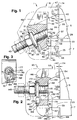
- Fig. 1 is a side elevational view, partially in section, of a clamping apparatus according to the invention shown in a clamping position in solid lines and a detached position in phantom lines.
- Fig. 2 is a side elevational view, partially in section, of a second embodiment of a clamping apparatus according to the invention and shown in a clamping position in solid lines and a detached position in phantom lines.
- Fig. 3 is a reduced and fragmentary elevational view of the second embodiment with portions removed to show the detail thereof.
- Fig. 1 illustrates a clamping apparatus of the invention, generally designated 1, for clamping first and second separable components illustrated by a platen 5 and a die 7, respectively.
- the apparatus 1 generally includes a support member in the form of a block 10, a mounting member in the form of a threaded stud 15, a generally C-shaped clamping member 18, a retaining member in the form of a flanged nut 20, and a retaining washer 22.
- a plurality of clamping apparatus 1 are positioned about the periphery of the platen 5 and the die 7 for securing the die 7 at a lip or shoulder 23 thereof in a position adjacent to the platen 5.
- the platen 5 and die 7 shown in Fig. 1 are an upper component of a press (not shown) and die set that would include a lower platen (not shown) and a lower die (not shown) which would also be attached by a plurality of clamping apparatus 1.
- the clamping apparatus 1 also may be utilized with a die and attached carrier plate combination (not shown) wherein a die would be fixed to a carrier plate and the plate would include a lip or shoulder similar to the lip 23 for securing the die/carrier plate assembly to a position adjacent to the platen 5.
- the block 10 is welded or otherwise fixed at a surface 24 to a vertical outer surface 25 of the platen 5 near a lower edge 28 thereof.
- support blocks 10 (and connected components 15, 18, 20 and 22 of the clamping apparatus 1) are preferably positioned about the periphery of the platen 5 in spaced relation about every 43.2 cm's (17 inches).
- more or fewer blocks 10 may be required depending upon the size and weight of the die 7.
- the size of the block 10 (and the other components of the clamping apparatus 1) may vary with the size and weight of the die 7.
- the block 10 has an upper inclined or sloping surface 30 and a lower inclined surface 32.
- the incline of surface 30 may range from about 15° to about 35° with respect to the horizontal and is preferably about 25° with respect to the horizontal and slopes in a downward direction away from the upper platen 5 for use in clamping a top die 7 as illustrated by Fig. 1. If being used for attaching a lower die (not shown) to a lower platen (not shown), the surface 30 would slope in an upward direction away from a lower platen when attached thereto.
- the lower surface 32 is illustrated generally parallel to the upper inclined surface 30 however, this is not required. The surface 32 need only be oriented so as to be spaced from the surface of the shoulder 23 of the die 7 when the apparatus 1 is clamping the die 7 to the platen 5.
- the block 10 also includes upper and lower welding ledges 36 and 37, respectively, located near the surface 24 providing a generally horizontal or slightly inclined surface for a weld 40 or other attachment means that does not interfere with the clamp 18 or the die 7.
- the width of the welding ledges 36 and 37 are determined by the size of the block 10 and the weight of the die 7, and are preferably at least 10 mm wide for use with the 3.1 m x 7.6 m (10 x 25 ft.) die described above.
- the block 10 may be made from alloy steel or other materials that can withstand the high temperatures reached by the platen 5.
- the block 10 further includes a generally cylindrical bore or aperture (not shown) having an opening at a generally vertical surface 42 and near the lower edge 32.
- the bore is tapped or otherwise adapted to engage the mounting stud 15 and has a central axis generally parallel to the surface 30 and is otherwise located generally centrally within the block 10.
- the mounting member or threaded stud 15 is screwed or otherwise fixed at a threaded end (not shown) into the bore (not shown) of the block 10 and extends outwardly from the surface 42.
- the stud 15 is positioned generally parallel to the upper inclined surface 30 of the block 10.
- the stud 15 is also threaded between an outer end 45 and a generally central location therealong with the threads adapted for engagement with the inner threads of the nut 20.
- the stud 15 is made from a strong material, preferably of an alloy steel such as stainless steel.
- the generally C-shaped clamping member 18 includes an upper leg 47, a mid-section 48, and a lower leg 49 and has a bore or aperture 51 extending through the mid-section 48.
- a surface 52 of the bore 51 is adapted to slidably receive and surround the stud 15 as a sleeve.
- the bore 51 is angularly oriented in the clamping member 18 in a direction parallel to a surface 54 of the upper leg 47, thereby orienting the surface 54 parallel to the block surface 30 when the clamping member 18 is slidably mounted on the stud 15 with the stud 15 surrounded by the surface 52 of the bore 51.
- the surface 54 of the upper leg 47 engages the surface 30 of the block 10 when the apparatus 1 is in a clamping position as shown in solid lines in Fig. 1.
- the clamping member 18 is made from alloy steel or other strong, heat resistant material.
- the lower leg 49 of the clamping member 18 includes an upper face or surface 57 that is adapted to be positioned generally horizontally when the stud 15 is surrounded by the surface 52 of the bore 51.
- the upper surface 57 engages a lower surface 59 of the lip 23 of the die 7 when the apparatus 1 is in a clamping position as shown in solid lines in Fig. 1. Because both the upper surface 57 of the clamping member 18 and the lower surface 59 of the lip 23 are generally parallel in orientation, the surface 59 may slide easily with respect to the surface 57 as the die 7 expands or contracts during heating or cooling.
- the lower leg 49 and mid-section 48 of the clamping member 18 are designed to provide a gap, illustrated by reference numeral 61 in Fig. 1, between an outer edge 63 of the lip 23 of the die 7 and a facing surface 65 of the mid-section 48 when the apparatus 1 is in a clamping position.
- the gap 61 provides space for thermal expansion of the die 7 and adjustment of the clamping member 18 as the die 7 is heated by the platen 5.
- the lower leg 49 of the clamping member 18 is also designed to provide a gap illustrated by reference numeral 68 in Fig. 1 located beneath the lip 23 and between a surface 71 of the lower leg 49 and a surface 73 of the die 7 when the apparatus 1 is in a clamping position.
- the gap 68 also provides space for adjustment of the apparatus 1 due to thermal expansion of the die 7 and wear or other thickness variation of the lip 23.
- the upper leg 47 of the clamping member 18 is also designed to provide a gap illustrated by reference numeral 74 in Fig. 1 located between a surface 75 of the leg 47 and surface 25 of the platen 5.
- the gap 74 also provides space for adjustment of the apparatus 1 due to thermal expansion of the die 7.
- An additional gap 76 also providing space for adjustment of the apparatus 1 due to thermal expansion of the die 7 is located between the surface 65 of the mid-section 48 of the clamp 18 and the surface 42 of the block 10.
- Each of the gaps 61, 68, 74 and 76 also compensates for a decrease in the thickness of the lip 23 due to wear which might otherwise result in the clamping member 18 abutting the vertical surfaces of the block 10, platen 5 or die 7 resulting in a failure of the apparatus 1 to adequately secure the die 7 to the platen 5.
- An outer surface 77 of the mid-section 48 of the clamping member 18 is generally oriented perpendicularly to the bore 51.
- the mid-section 48 has a generally shallow cylindrical recess 80 located near the surface 77 and concentric with the bore 51.
- the diameter of the recess 80 is larger than the diameter of the bore 51.
- a cylindrical wall 82 and a flat surface 84 define the boundary of the recess 80.
- the flat surface 84 is parallel to the surface 77.
- the wall 82 and surface 84 of the recess 80 sleeve a flange portion 87 of the flanged nut 20.
- the flange portion 87 is integral or fixed to a head portion 90 located outside of the recess 80.
- the threaded nut 20 is mounted on the stud 15 and held adjacent to the clamping member 18 by the washer 22.
- the generally circular, flat washer 22 is welded or otherwise fixed to surface 77 of the midsection 48.
- the washer 22 includes an inner edge 92 that overhangs the cylindrical wall 82 of the recess 80 thereby partially covering the recess 80.
- the inner edge 92 is generally circular in shape and has a diameter that is smaller than the outer diameter of the flange portion 87 of the nut 20, thereby containing or restraining the flange portion 87 within the recess 80.
- the flange portion 87 is loosely held within the recess 80 thereby allowing the retaining member 20 to be freely rotatable with respect to the clamping member 18.
- the inner edge 92 may also be a shape other than circular and is preferably hexagonal or square, providing for greater bearing area against the flange portion 87.
- the washer 22 is preferably made from a cold drawn steel or other strong material.
- the clamping apparatus 1 is shown with an upper platen 5 and upper die 7 in Fig. 1.
- the apparatus 1 may also be utilized with a lower platen and lower die by placing it in an inverted position (i.e. upside down) from the orientation shown in Fig. 1.
- a plurality of blocks 10 are initially welded or otherwise fixed to a platen 5 of a frame-type press (not shown).
- a stud 15 is mounted on each block 10 and a clamping member 18 with a connected flanged nut 20 is mounted on the stud 15 near the end 45 (the detached position shown in Fig. 1 in phantom lines).
- the die 7 is lifted (or lowered) into the proximity of the platen 5 and clears the clamping apparatus 1 by way of a clearance or gap illustrated by the reference numeral 95 shown in Fig. 1.
- An operator may use a socket wrench with a long extension to rotate the head portion 90 of the nut 20 and thereby slide the clamping member 18 toward the heated platen 5 until the surface 54 of the clamping member 18 frictionally engages the inclined surface 30 of the block 10 and the lower leg surface 57 frictionally engages the surface 59 of the die 7 as shown in solid lines in Fig. 1.
- the socket wrench may be used to rotate the retaining nut 20 to the left or to the right and thereby move the clamping member 18 to any chosen position along the mounting stud 15, generally between the detached position shown in phantom lines and the clamping position shown in solid lines in Fig. 1.
- the clamping process using the apparatus 1 takes only a short amount of time and all parts are contained on the stud 15 (i.e. no loose parts fall off and cause damage to the press).
- the die 7 is initially clamped loosely to the platen 5 to allow for expansion of the die upon heating. Because the die 7 is generally long and flat, most the heat expansion and contraction occur in a horizontal or lengthwise direction. The die surface 59 therefore easily slides in a horizontal direction with respect to the clamp surface 57 when clamped loosely by the apparatus 1. Thus, no temporary fasteners are required. As the die 7 is heated by the platen 5, the die 7 may expand horizontally into the gap areas 61, 68, 74 and 76. Also, thermal expansion of the die 7 in the vertical direction and wear or other thickness variation of the lip 23 causes the clamping member 18 to slide along the inclined surface 30 of the block 10.
- the expansion of the die 7 requires adjustment of the clamping member 18, an operator may simply adjust the position of the member 18 by turning the nut 20 while being at a safe distance from the heated platen 5 and die 7, using a socket wrench on a long extension. With a simple adjustment of the nut 20, the clamping member 18 slides either vertically and toward the platen 5 or vertically and away from the platen 5 along the inclined surface 30.
- each of the clamping apparatus 1 is tightened.
- the socket on a long extension is used to engage the nut head 90, rotate the nut 20 and thereby slide the connected clamping member 18 outwardly away from the ramp block 10 and the die 7 to the detached position shown in phantom lines in Fig. 1.
- Figs. 2 and 3 illustrate a second embodiment of a clamping apparatus according to the invention, generally designated by the reference numeral 101 for clamping first and second separable components illustrated by a platen 5 and a die 7 respectively.
- the apparatus 101 generally includes a support member or block 110, a mounting member or threaded stud 115, a generally C-shaped clamping member 118, a retaining member or flanged nut 120 and a flat and oblong retaining washer 122, made of materials and adapted to cooperate with each other and with the platen 5 and a die 7 similar to the support block 10, threaded stud 15, clamping member 18, flanged nut 20 and retaining washer 22 of the apparatus 1 shown in Fig. 1.
- the apparatus 101 differs from the apparatus 1 with respect to the orientation of a bore in the block 110, the orientation of the stud 115 and the configuration of the washer 122 and some of the elements or features of the clamping member 118.
- a plurality of clamping apparatus 101 are positioned about the periphery of the platen 5 and die 7 for securing the die 7 at a lip or shoulder 23 thereof in a position adjacent to the platen 5.
- the block 110 has upper and lower inclined or sloping surfaces 130 and 132 respectively, similar to surfaces 30 and 32 of the block 10 of apparatus 1.
- the block 110 also includes a bore (not shown) that is oriented generally horizontally when the block 110 is fixed to the platen 5.
- the stud 115 when fixed into the bore is also positioned generally horizontally and is perpendicular to a surface 142 of the support block 110.
- the stud 115 is threaded between an outer end 145 and a generally central location therealong with the threads adapted for engagement with the inner threads of the nut 120.
- the generally C-shaped clamping member 118 includes an upper leg 147, mid-section 148 and lower leg 149 and has a slot 151 extending through the mid-section 148.
- a surface 152 of the slot 151 is adapted for slidably surrounding the stud 115.
- the slot 151 is slightly wider than the diameter of the stud 115 with respect to the horizontal.
- the slot 15 is of a length that provides for adequate movement of the clamping member 118 in a vertical direction corresponding to the extent of vertical thermal expansion of the die 7, thereby allowing for vertical adjustment of the clamping member 118 when the apparatus 1 is in a clamping position with a surface 154 of the clamping member 118 frictionally engaging the surface 130 of the support block 110 as shown in solid lines in Fig. 2.
- the lower leg 149 of the clamping member 118 includes an upper face or surface 157 that is adapted to be positioned generally horizontally when the stud 115 is surrounded by the surface 152 of the slot 151.
- the upper surface 157 engages the lower surface 59 of the lip 23 of the die 7 when the apparatus 1 is in a clamping position as shown in solid lines in Fig. 2.
- the legs 147 and 149 and mid-section 148 of the clamping member 118 are designed to provide gaps, illustrated by reference numerals 161, 168, 174 and 176 in Fig 2 similar in orientation and function to the gaps 61, 68, 74 and 76 respectively described with respect to apparatus 1.
- An outer surface 177 of the mid-section 148 of the clamping member 118 is generally oriented vertically and perpendicularly to the slot 151.
- the mid-section 148 has a generally shallow, oblong recess 180 located near the surface 177.
- the width and length of the recess 180 are slightly larger than the width and length respectively of the slot 151.
- a wall 182 and a flat surface 184 define the boundary of the recess 180.
- the flat surface 184 is parallel to the surface 177.
- the oblong, flat washer 122 is fixed to the surface 177 in a manner and orientation similar to what is described above with respect to the washer 22 and surface 77 of apparatus 1.
- the washer 122 and the wall 182 and the surface 184 of the recess 180 loosely contain and constrain a flange portion 187 of the flanged nut 120 with the washer 122 partially covering the recess 180.
- the flange portion 187 is integral or fixed to a head portion 190 located outside of the recess 180.
- the head portion 190 is therefore freely rotatable with respect to the clamping member 118.
- the combination of the threaded nut 120 and the clamping member 118 is mounted on the stud 115.
- a plurality of blocks 110 are initially welded or otherwise fixed to a platen 5 of a frame-type press (not shown) -
- a stud 115 is mounted on each block 110 and a clamping member 118 with a connected flanged nut 120 is mounted on the stud 115 near the end 145 (the detached position as shown in phantom lines in Fig. 2).
- the die 7 is lifted into the proximity of the platen 5 and clears the clamping apparatus 101 by way of a clearance or gap illustrated by the reference numeral 195 shown in Fig. 2.
- An operator may use a socket wrench with a long extension to rotate the nut head 190 and thereby slide the clamping member 118 toward the heated platen 5 until the surface 154 of the clamping member 118 frictionally engages with the inclined surface 130 of the block 110 and the lower leg surface 157 frictionally engages the surface 59 of the die 7 as shown in solid lines in Fig. 2.
- the socket wrench may be used to rotate the retaining nut 120 to the left or to the right and thereby move the clamping member 118 to any chosen position along the mounting stud 115, generally between the detached position shown in phantom lines and the clamping position shown in solid lines in Fig. 2.
- the die 7 is initially clamped loosely to the platen 5 to allow for expansion of the die upon heating. Because the die 7 is generally long and flat, most of the heat expansion and contraction occur in a horizontal or lengthwise direction. As the die 7 is heated by the platen 5, the die 7 may expand horizontally into the gap areas 161, 168, 174 and 176 and slide horizontally with respect to the surface 157. Thus, no temporary fasteners are required. Also, thermal expansion of the die 7 in the vertical direction and wear or other thickness variation of the lip 23 causes the clamping member 118 to slide along the inclined surface 130 of the block 10 with the clamping member 118 being adjustable in a vertical direction within the slot 151.
- an operator may simply adjust the position of the clamping member 118 by turning the nut 120 while being at a safe distance from the heated platen 5 and die 7 by using a socket wrench on a long extension.
- each of the clamping apparatus 101 is tightened.
- the socket on a long extension is used to engage the nut head 190, rotate the nut 120 and thereby slide the connected clamping member 118 outwardly away from the ramp block 110 and the die 7 to the detached position shown in phantom lines in Fig. 2.
Landscapes
- Engineering & Computer Science (AREA)
- General Engineering & Computer Science (AREA)
- Mechanical Engineering (AREA)
- Mounting, Exchange, And Manufacturing Of Dies (AREA)
- Clamps And Clips (AREA)
- Moulds For Moulding Plastics Or The Like (AREA)
Claims (14)
- Dispositif pour bloquer un premier et second composant (5, 7) séparable l'un contre l'autre contenant une pièce de blocage (18, 118) en forme de C, une pièce de fixation (15, 115) et une pièce de retenue (20, 120), ledit dispositif étant caractérisé par- une pièce de support (10, 110) ayant une surface inclinée (30) et étant adoptée à être fixée audit premier composant (5),- la pièce de fixation (15 115) fixée à ladite pièce de support (10, 110) et avançant de celle-ci, et- la pièce de blocage (18, 118) fixée sur ladite pièce de fixation (15, 115) de façon coulissable et étant mobile entre une position de blocage et une position détachée là-dessus, ladite pièce de blocage (18, 118) ayant un premier et un second piéd (47, 49, 147, 149)
où, lorsque se trouvant dans ladite position de blocage, ledit premier piéd (49, 149) ayant une première surface (57, 157) est adapté à être mis en prise avec le second composant (7) par friction et ledit second piéd (47, 147) ayant une seconde surface (54 154) est adaptée à être mis en preise avec la pièce de support (10, 110) par friction le long de la surface inclinée (30, 130), et où ledit premier et ledit second piéd (47, 49, 147, 149) retiennent ledit premier composant (5) en contiguïté audit second composant (7) au cours de la dilatation thermique des composants (5, 7) pendant qu'ils restent dans ladite position de blocage, et où, lorsque se trouvant dans ladite position détachée, on peut enlever ladite pièce de blocage (18, 118) non seulement dudit premier mais aussi dudit second composant (5, 7). - Dispositif d'après la revendication 1 comportant une pièce de retenue (20, 120) fixée sur ladite pièce de fixation (15, 115), ladite pièce de retenue (20, 120) étant connectée à ladite pièce de blocage (18, 118) et étant adaptée à retenir ladite pièce de blocage (18, 118) sur ladite pièce de fixation (15, 115), où l'on peut mettre ladite pièce de retenue (20, 120) en rotation libre relativement à ladite pièce de blocage (18, 118)
- Dispositif d'après la revendication 2 dans lequel ladite pièce de retenue (20, 120) est adaptée à retenir ladite pièce de retenue (20, 120) sur ladite pièce de fixation (15, 115) à une position sélectionnée y compris ladite position de blocage et ladite position détachée et des positions entre les deux.
- Dispositif d'après quelconque des revendications précédentes dans lequel ladite pièce de blocage (18, 118) est généralement en forme de C et définit un renfoncement (80, 180).
- Dispositif d'après quelconque des revendications précédentes dans lequel ladite pièce de fixation est un boulon fileté (15,115).
- Dispositif d'après quelconque des revendications précédentes dans lequel ladite pièce de blocage (18, 118) est généralement en forme de C et montre une orifice (51 151) et un renfoncement (80,180), ladite orifice (51,151) étant adaptée à loger ledit boulon (15, 115) de façon coulissable et ledit renfoncement (80, 180) étant adapté à loger ladite pièce de retenue (20,120).
- Dispositif d'après quelconque des revendications précédentes dans lequel ladite pièce de blocage (118) est généralement en forme de C et définit une fente (151) et un renfoncement (180), ladite fente (151) avançant dans une direction généralement verticale et étant adaptée à loger ladite pièce de fixation (115) de façon coulissable.
- Dispositif d'après quelconque des revendications précédentes dans lequel ladite pièce de retenue est un écrou (20, 120) ayant une partie de tête (90, 190) et une partie de collerette (87, 187), ladite partie de collerette (87, 187) étant lâchement encastrée dans ledit renfoncement (80, 180).
- Dispositif d'après quelconque des revendications précédentes comportant une bague (22, 122) fixée à ladite pièce de blocage (18, 118) er pariellement couvrant ledit renfoncement (80, 180), ladite bague (22, 122) étant adaptée à couvrir lâchement ladite partie de collerette (87, 187) dans ledit renfoncement (80, 180)
- Dispositif d'après quelconque des revendications précédentes dans lequel ladite pièce de support (10, 110) montre de plus une surface généralement verticale (42, 142) et ladite pièce de fixation (15, 115) avance de ladite surface verticale (42, 142).
- Dispositif d'après quelconque des revendications précédentes dans lequel ladite pièce de fixation (15) avance de ladite pièce de support (10) dans une direction parallelement à ladite surface inclinée (30).
- Dispositif d'après quelconque des revendications précédentes dans lequel ladite pièce de fixation (115) avance dans une direction généralement perpendiculaire à ladite surface verticale (142).
- Dispositif d'après quelconque des revendications précédentes dans lequel ladite pièce de blocage (18, 118) montre une face (59, 159) adaptée à mettre ledit second composant (7) en prise par friction, ladite face (59, 159) montrant un déroulement géneralement parallel à la direction principale de la dilatation thermal et de la contraction du second composant (7).
- Dispositif d'après quelconque des revendications précédentes dans lequel lesdits premier et second composants sont, respectivement, un plaque d'appui (5) échauffé d'une presse du type de chassis et un outil d'estampage (7) avec une surface aplatie (18)
Applications Claiming Priority (2)
| Application Number | Priority Date | Filing Date | Title |
|---|---|---|---|
| US88070392A | 1992-05-08 | 1992-05-08 | |
| US880703 | 1992-05-08 |
Publications (2)
| Publication Number | Publication Date |
|---|---|
| EP0569023A1 EP0569023A1 (fr) | 1993-11-10 |
| EP0569023B1 true EP0569023B1 (fr) | 1997-07-30 |
Family
ID=25376890
Family Applications (1)
| Application Number | Title | Priority Date | Filing Date |
|---|---|---|---|
| EP93107404A Expired - Lifetime EP0569023B1 (fr) | 1992-05-08 | 1993-05-07 | Moyen de serrage pour la matrice d'une presse |
Country Status (4)
| Country | Link |
|---|---|
| US (1) | US5346328A (fr) |
| EP (1) | EP0569023B1 (fr) |
| CA (1) | CA2094569C (fr) |
| DE (1) | DE69312561T2 (fr) |
Families Citing this family (5)
| Publication number | Priority date | Publication date | Assignee | Title |
|---|---|---|---|---|
| US6427996B1 (en) | 2000-11-01 | 2002-08-06 | Atlas Technologies, Inc. | Workpiece transfer support apparatus |
| US7296946B2 (en) * | 2001-11-30 | 2007-11-20 | Microsoft Corporation | Ring binder mechanism |
| US20070063382A1 (en) * | 2005-09-16 | 2007-03-22 | Larry Cole | Mold quick disconnect apparatus |
| DE202007008471U1 (de) * | 2007-06-13 | 2007-09-27 | Leichtmetallbau Schletter Gmbh | Vorrichtung zum Verbinden einer Profilschiene mit einem anderen Bauteil |
| JP6962811B2 (ja) * | 2017-12-26 | 2021-11-05 | コスモ工機株式会社 | フランジ離間防止装置 |
Family Cites Families (20)
| Publication number | Priority date | Publication date | Assignee | Title |
|---|---|---|---|---|
| US2603380A (en) * | 1952-07-15 | Head and shell joint foe drier drums | ||
| US255974A (en) * | 1882-04-04 | Butter-case | ||
| US1019343A (en) * | 1911-07-06 | 1912-03-05 | Mathew Mulholland | Hatch-cover fastener. |
| US1924027A (en) * | 1932-08-31 | 1933-08-22 | Thomas H Clark | Burial vault |
| US2240660A (en) * | 1940-02-26 | 1941-05-06 | Edgar T Meakin | Extrusion mill |
| US2393078A (en) * | 1943-10-12 | 1946-01-15 | Wager Robert Hudson | Inverted vent check valve |
| DE873473C (de) * | 1951-12-07 | 1953-04-20 | Milton Paul Laurent | Verschluss |
| US3195186A (en) * | 1962-06-13 | 1965-07-20 | Inv S Finance Corp | Apparatus for clamping mold parts |
| FR1400227A (fr) * | 1964-07-06 | 1965-05-21 | Smeralovy Zd Y Narodni Podnik | Dispositif de fixation de matrices, notamment pour presses à forger à manivelle et machine équipée d'un tel dispositif |
| US3525495A (en) * | 1968-06-04 | 1970-08-25 | Louis Philippe Brosseau | Hanger assembly for suspended concrete forms |
| US3995685A (en) * | 1975-05-19 | 1976-12-07 | Stanko John J | Foundry flask clamp |
| FR2342831A1 (fr) * | 1976-03-03 | 1977-09-30 | Ind Tech Ameublemen | Dispositif de verrouillage d'un moule |
| DE3011200A1 (de) * | 1980-03-22 | 1981-10-01 | Desma-Werke Gmbh, 2807 Achim | Vorrichtung zum herstellen von formlingen aus kunststoff oder gummi |
| US4365792A (en) * | 1980-08-26 | 1982-12-28 | Johns Consolidated Limited | Hydraulic mould clamp |
| US4500275A (en) * | 1983-12-23 | 1985-02-19 | Sharp Die & Mold Company, Inc., A Subsidiary Of R & R Plastic Material, Inc. | Quick change locator clamp assembly for plastic molding machine |
| US4602497A (en) * | 1984-01-27 | 1986-07-29 | Wallis Bernard J | Die clamping arrangement |
| DE3664373D1 (en) * | 1985-08-09 | 1989-08-17 | Framatome Sa | Device for placing and holding a cover for an opening inside a vessel |
| FR2651843B1 (fr) * | 1989-09-12 | 1991-12-20 | Aerospatiale | Systeme de verrouillage a came. |
| JPH0625688Y2 (ja) * | 1990-04-23 | 1994-07-06 | 旭光学工業株式会社 | 複数の板材の挟持構造 |
| DE4029957A1 (de) * | 1990-09-21 | 1992-03-26 | Standard Elektrik Lorenz Ag | Schraubzwinge |
-
1993
- 1993-04-21 CA CA002094569A patent/CA2094569C/fr not_active Expired - Fee Related
- 1993-05-07 DE DE69312561T patent/DE69312561T2/de not_active Expired - Fee Related
- 1993-05-07 EP EP93107404A patent/EP0569023B1/fr not_active Expired - Lifetime
- 1993-09-28 US US08/129,875 patent/US5346328A/en not_active Expired - Fee Related
Also Published As
| Publication number | Publication date |
|---|---|
| EP0569023A1 (fr) | 1993-11-10 |
| CA2094569C (fr) | 1998-07-14 |
| CA2094569A1 (fr) | 1993-11-09 |
| US5346328A (en) | 1994-09-13 |
| DE69312561D1 (de) | 1997-09-04 |
| DE69312561T2 (de) | 1998-01-22 |
Similar Documents
| Publication | Publication Date | Title |
|---|---|---|
| US6364302B2 (en) | Modular system and fixture for positioning and clamping a workpiece | |
| US4787505A (en) | Workpiece carrier assembly | |
| US4957402A (en) | T-nut with furrows | |
| JPH0811343B2 (ja) | 被加工部品の装着装置 | |
| US4431474A (en) | Thermocompression bonding apparatus | |
| US4183387A (en) | T-Bolt adapter | |
| WO2001061122A1 (fr) | Dispositif de fixation | |
| US5810341A (en) | Truss table with integrated positioning stops | |
| US5992285A (en) | Floating punch holder | |
| US5346328A (en) | Press die clamp | |
| US20170174485A1 (en) | Adjustable Universal Adaptor for a Lifting Jack | |
| EP0995541A2 (fr) | Dispositif de fixation autonivelant pour appareil de soudage | |
| US5509644A (en) | Modified T-slot arrangement | |
| US4472917A (en) | Fixing device for mounting a plate on the flange of a beam | |
| CN111036722A (zh) | 铸件矫形装置和铸件矫形方法 | |
| EP0149513B1 (fr) | Ancrages pour rails de voie | |
| EP0723118B1 (fr) | Dispositif de fixation de radiateur au fondement | |
| CN219112790U (zh) | 一种冷镦机弹簧复位夹钳 | |
| US4372144A (en) | Wrap ring assembly for precision no-draft forging | |
| US6058675A (en) | Angularly orientable post | |
| KR200403083Y1 (ko) | 지그 바이스 | |
| SU1324809A1 (ru) | Устройство дл сборки под сварку изделий из листового материала | |
| US3777436A (en) | Quick release mechanism for continuous casting mold support frame | |
| US11633901B2 (en) | Thermoplastic sheet heating appliance | |
| KR100655950B1 (ko) | 지그 바이스 |
Legal Events
| Date | Code | Title | Description |
|---|---|---|---|
| PUAI | Public reference made under article 153(3) epc to a published international application that has entered the european phase |
Free format text: ORIGINAL CODE: 0009012 |
|
| AK | Designated contracting states |
Kind code of ref document: A1 Designated state(s): DE IT SE |
|
| 17P | Request for examination filed |
Effective date: 19940429 |
|
| 17Q | First examination report despatched |
Effective date: 19950328 |
|
| GRAG | Despatch of communication of intention to grant |
Free format text: ORIGINAL CODE: EPIDOS AGRA |
|
| GRAH | Despatch of communication of intention to grant a patent |
Free format text: ORIGINAL CODE: EPIDOS IGRA |
|
| GRAH | Despatch of communication of intention to grant a patent |
Free format text: ORIGINAL CODE: EPIDOS IGRA |
|
| GRAA | (expected) grant |
Free format text: ORIGINAL CODE: 0009210 |
|
| AK | Designated contracting states |
Kind code of ref document: B1 Designated state(s): DE IT SE |
|
| REF | Corresponds to: |
Ref document number: 69312561 Country of ref document: DE Date of ref document: 19970904 |
|
| ITF | It: translation for a ep patent filed | ||
| PLBE | No opposition filed within time limit |
Free format text: ORIGINAL CODE: 0009261 |
|
| 26N | No opposition filed | ||
| PGFP | Annual fee paid to national office [announced via postgrant information from national office to epo] |
Ref country code: SE Payment date: 20020418 Year of fee payment: 10 |
|
| PGFP | Annual fee paid to national office [announced via postgrant information from national office to epo] |
Ref country code: DE Payment date: 20020520 Year of fee payment: 10 |
|
| PG25 | Lapsed in a contracting state [announced via postgrant information from national office to epo] |
Ref country code: SE Free format text: LAPSE BECAUSE OF NON-PAYMENT OF DUE FEES Effective date: 20030508 |
|
| PG25 | Lapsed in a contracting state [announced via postgrant information from national office to epo] |
Ref country code: DE Free format text: LAPSE BECAUSE OF NON-PAYMENT OF DUE FEES Effective date: 20031202 |
|
| EUG | Se: european patent has lapsed | ||
| PG25 | Lapsed in a contracting state [announced via postgrant information from national office to epo] |
Ref country code: IT Free format text: LAPSE BECAUSE OF NON-PAYMENT OF DUE FEES Effective date: 20050507 |