EP0569088A1 - Vérin pneumatique à verrouillage hydraulique - Google Patents
Vérin pneumatique à verrouillage hydraulique Download PDFInfo
- Publication number
- EP0569088A1 EP0569088A1 EP93201250A EP93201250A EP0569088A1 EP 0569088 A1 EP0569088 A1 EP 0569088A1 EP 93201250 A EP93201250 A EP 93201250A EP 93201250 A EP93201250 A EP 93201250A EP 0569088 A1 EP0569088 A1 EP 0569088A1
- Authority
- EP
- European Patent Office
- Prior art keywords
- piston
- working
- chamber
- stable position
- compressed air
- Prior art date
- Legal status (The legal status is an assumption and is not a legal conclusion. Google has not performed a legal analysis and makes no representation as to the accuracy of the status listed.)
- Withdrawn
Links
- 239000012530 fluid Substances 0.000 claims abstract description 18
- 230000007246 mechanism Effects 0.000 claims description 27
- 238000013016 damping Methods 0.000 claims description 6
- 238000002485 combustion reaction Methods 0.000 claims description 3
- 238000013459 approach Methods 0.000 claims 16
- 238000005381 potential energy Methods 0.000 abstract description 5
- 230000000977 initiatory effect Effects 0.000 abstract 1
- 238000007789 sealing Methods 0.000 description 6
- 238000004891 communication Methods 0.000 description 2
- 230000006835 compression Effects 0.000 description 2
- 238000007906 compression Methods 0.000 description 2
- 230000000694 effects Effects 0.000 description 2
- 150000001875 compounds Chemical class 0.000 description 1
- 230000007423 decrease Effects 0.000 description 1
- 230000003247 decreasing effect Effects 0.000 description 1
- 238000004146 energy storage Methods 0.000 description 1
- 238000003780 insertion Methods 0.000 description 1
- 230000037431 insertion Effects 0.000 description 1
- JEIPFZHSYJVQDO-UHFFFAOYSA-N iron(III) oxide Inorganic materials O=[Fe]O[Fe]=O JEIPFZHSYJVQDO-UHFFFAOYSA-N 0.000 description 1
- 238000003754 machining Methods 0.000 description 1
Images


Classifications
-
- F—MECHANICAL ENGINEERING; LIGHTING; HEATING; WEAPONS; BLASTING
- F01—MACHINES OR ENGINES IN GENERAL; ENGINE PLANTS IN GENERAL; STEAM ENGINES
- F01L—CYCLICALLY OPERATING VALVES FOR MACHINES OR ENGINES
- F01L9/00—Valve-gear or valve arrangements actuated non-mechanically
- F01L9/20—Valve-gear or valve arrangements actuated non-mechanically by electric means
-
- F—MECHANICAL ENGINEERING; LIGHTING; HEATING; WEAPONS; BLASTING
- F01—MACHINES OR ENGINES IN GENERAL; ENGINE PLANTS IN GENERAL; STEAM ENGINES
- F01L—CYCLICALLY OPERATING VALVES FOR MACHINES OR ENGINES
- F01L9/00—Valve-gear or valve arrangements actuated non-mechanically
- F01L9/10—Valve-gear or valve arrangements actuated non-mechanically by fluid means, e.g. hydraulic
- F01L9/16—Pneumatic means
Definitions
- the present invention relates to a bistable straight line motion actuator mechanism of a type suitable for actuating a poppet valve in an internal combustion engine. More particularly, the invention relates to an electronically controlled, pneumatically powered actuator which is hydraulically latched.
- U.S. Patent No. 5,022,359 discloses a mechanism which uses a low air pressure (about 10 psi) to hold a working piston in its first stable position (engine valve closed).
- a magnetic control valve is electronically switched, high air pressure (about 100 psi) drives the piston toward its second stable position compressing the air in front of it. This motion admits hydraulic fluid to an expansion chamber via a ball check.
- the control valve has returned to its initial state, cutting off the air supply, and the compressed air behind the piston is released to atmosphere.
- the air in front of the piston is fully compressed, but the ball check closes and hydraulic fluid in the expansion chamber prevents motion back toward the first stable position, thereby maintaining the engine valve open.
- an electronically controlled magnetic plunger forces the ball check open, and the compressed air (stored potential energy) forces the piston back toward its first stable position. Air is compressed in front of the moving piston to dampen its motion, but this air is released just as the piston reaches its first stable position.
- U.S. Patent No. 5,022,359 represents an improvement over the prior art insofar as externally derived propulsion air is used only to open the engine valve, and not to close it.
- the compressed air consumed is therefore decreased to about half the air consumed in prior pneumatically powered systems.
- two separately controlled magnetic mechanisms, one for the air control valve and one for the plunger to release the ball check, are require. Since the air control valve is rather large, a large electromagnetic latch is required. Further, due to the time required to pressurize the piston with air, after the control valve is switched, the response time is slow and not suited to use at high RPM.
- the present invention provides a fully symmetric actuator mechanism wherein a working piston is pneumatically driven by opposed sources of compressed air in two opposed directions, and hydraulically latched in opposed stable positions by a two position hydraulic latch which is the sole electronically controlled component.
- the latch is in effect a two-directional check valve which in each position admits fluid to a respective hydraulic chamber to prevent reverse movement of the working piston.
- the check valve is electronically switched, hydraulic fluid passes between the two hydraulic chambers and the latch is released, permitting one of the sources of compressed air to drive the working piston as a working chamber behind the piston expands.
- the source of compressed air connected to the expanding working chamber is cut off.
- the compressed air expanding in the working chamber is exhausted through ports exposed by the piston. Meanwhile, air is compressed in a working chamber in front of the piston, which working chamber is connected to another source of compressed air in the final stage of movement. This provides damping for the piston without any additional loss of air or air pressure.
- the two sources of compressed air are actually just cavities connected to a single source of air which replenishes air lost from an expanding working chamber through the exhaust ports after work is done.
- the small amount of make-up air is provided when each cavity is connected to its working chamber by action of the advancing piston.
- the actuator according to the invention is simpler than the prior art insofar as only one electronically actuated magnetic latch is needed. Since this latch is only moving a low mass valve of the two-way check valve, the magnets are relatively small as compared to most prior art arrangements. Due to the low mass of the check valve, response times are relatively fast.
- the two-way check valve provides for a very positive hydraulic latching in both stable positions, and at the same time permits a very fast response. That is, in addition to the low mass, the high pneumatic pressure on the main piston faces in the latched condition provides for a rapid commencement of movement when the check valve is reversed on electronic command.
- the engine valve tends to become slightly unseated when closed.
- a novel cinching arrangement wherein the engine valve is connected to the working piston through spring means which cause it to remain fully seated. More particularly, the valve stem is received through a bore in the working piston and attached to a seating piston in a small pneumatic chamber in the piston. This chamber is connected to high pressure air only when the engine valve is closed, causing it to be fully seated regardless of compression of hydraulic fluid and differential expansion of engine parts. In addition to this pneumatic force there is also a spring in this chamber.
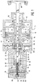
- the basic components of the actuator are the housing 10, pneumatically driven working piston 40, hydraulic latching piston 60, a magnetically driven two way check valve 70 for the hydraulic fluid, and the engine valve 80.
- the housing 10 has first and second pneumatic pressure cavities 12, 20 which are connected to a source of high pressure air at 100 psi.
- first and second working chambers 14, 15 In between the cavities 12, 20 are first and second working chambers 14, 15 having a common sleeve 16.
- the working piston 40 reciprocates in sleeve 16
- the first cavity 12 communicates intermittently with first working chamber 14
- the second cavity 20 communicates intermittently with the second working chamber 15.
- the first cavity 12 is cut off from the first working chamber 14, which is vented to atmosphere by exhaust ports 17.
- the second cavity 20 is connected to second working chamber 15 so that the piston 40 is pneumatically loaded toward the right.
- the total volume of the two working chambers 14, 15 is constant.
- the second cavity 20 is connected to a make-up chamber 22 by a galley 21; a flexible diaphragm 23 separates the chamber 22 into a pneumatic portion 22a and a hydraulic portion 22b.
- a spring and ball type check valve 25 permits hydraulic fluid to pass from chamber portion 22a to a first hydraulic chamber 27, but not in the opposite direction.
- the first hydraulic chamber 27 is separated from a second hydraulic chamber by a port 30 in which the two way check valve 70 reciprocates, and a hydraulic latching piston 60 which is fixed relative to pneumatic piston 40.
- the volumes of the first and second hydraulic chambers 27, 28 vary as the piston 60 reciprocates, but their total volume remains constant.
- the check valve 70 is fixed to a stem 74 which carries an armature disc 78 which is reciprocable in a gap 36 between a first permanent magnet 32 and a second permanent magnet 34.
- Each magnet 32, 34 is associated with a respective coil 33, 35 which can be energized to induce a magnetic field opposing the associated permanent magnet when it is desired to shift the check valve 70.
- the working piston 40 has a first working surface 42 facing the first working chamber 14 and spaced from a first sealing piston 45 by a constriction 43 and a shoulder 44.
- a second working surface 46 facing second working chamber 15 is spaced from a second sealing piston 50 by a second constriction 47 and a second shoulder 48.
- the sealing pistons 45, 50 pass through respective seals 13, 18 as the working piston 40 reciprocates to effect communication between cavities 12, 20 and respective working chambers 14, 15.
- a seal 49 on the outer circumference of the piston 40 engages the sleeve 16 to seal the working chambers from each other.
- the second sealing piston 50 has a internal bore 51 which is divided into a spring chamber 52 and a vented chamber 54 by a reciprocable seating piston 87.
- a galley 53 extends between chamber 52 and constriction 47 so that spring chamber 52 will always have the same pneumatic pressure as second working chamber 15.
- the opposite end of bore 51 is enclosed by a fixed disc 55 having a vent 56 to chamber 38 at atmospheric pressure.
- a stem 58 fixed at its one end to disc 55, is fixed at its other end to hydraulic piston 60.
- the engine valve 80 is integral to a stem 83 which is slideably received through a central bore 41 in working piston 40 and fixed at its other end to seating piston 87.
- a diaphragm spring 88 in the spring chamber 52 and the pneumatic pressure from galley 53 urge the piston 87 leftward to keep the engine valve 80 against its seat 82.
- the working piston 40, the hydraulic piston 60, the two way check valve 70, and the engine valve 80 are all in their first stable positions.
- Pneumatic pressure in the second working chamber 15 urges the working piston 40 toward its second stable position (rightward), but the hydraulic fluid in first hydraulic chamber 27 prevents the hydraulic piston 60 from moving rightward.
- the hydraulic pressure in first hydraulic chamber 27 is larger than the pneumatic pressure in chamber 15 by the same ratio as the surface areas.
- the hydraulic pressure in chamber 27 reaches 2500 psi against the 100 psi pneumatic pressure. While the hydraulic fluid is slightly compressible, the engine valve 80 remains seated by virtue of the spring force on seating piston 87.
- the engine computer causes an electrical pulse to energize the first coil 33, thereby overriding the first permanent magnet 32 and allowing the second permanent magnet 34 to draw the armature 78 leftward.
- the pressure in the first hydraulic chamber 27 is considerably greater by virtue of the pneumatic pressure on second surface 46 of the working piston. This pressure differential overrides the magnetic attraction sufficiently to unseat the check valve 70 in port 30 so that the hydraulic pressure tends to equalize in both the first and second hydraulic chambers 27, 28. If it falls below 100 psi, makeup fluid is admitted from chamber 22 by check valve 25.
- the drop in hydraulic pressure against the first surface 62 of piston 60 allows the 100 psi pneumatic pressure in second working chamber 15 to drive working piston 40 toward its second stable position (rightward) thus opening engine valve 80.
- the second pressure cavity 20 remains in communication with working chamber 15 until the shoulder 48 on second sealing piston 50 enters the second sleeve 18, whereupon the pressure in the second working chamber 15 decreases due to the expanding volume.
- the piston 40 has just reached the exhaust ports 17 so that ambient pressure prevails in the second working chamber 15. Meanwhile, the pneumatic pressure in first chamber 14 increases, converting the kinetic energy of the working piston into potential energy of the compressured air.
- the first shoulder 44 has just cleared the rust sleeve 13, so that the 100 psi source pressure in first cavity 12 prevails in the first working chamber 14 during the remainder of the piston movement. While 100 psi is greater than the ambient pressure in chamber 15, the momentum of the working piston and the engine valve continues to carry the assembly rightward moving the high pressure air in chamber 14 to chamber 12 as well as compressing the coil spring 85 inside first sealing piston 45. This provides additional damping and storage of potential energy. In a properly balanced system, the source pressure and the spring compression will bring the piston 40 to a halt without any impact.
- the working piston 40, the hydraulic piston 60, the two way check valve 70, and the engine valve 80 are all in their second stable positions.
- the pneumatic pressure in first cavity 12 and first working chamber 14 acts on first working surface 42 to urge the piston 40 toward its first stable position (leftward), and the loaded coil spring 85 compounds this force.
- the hydraulic fluid in the second hydraulic chamber 28 cannot escape through valve 70, and thus acts to latch the engine valve open.
- the pressure in second chamber 28 is considerably higher than that in first chamber 27, e.g. 2500 psi vs. 100 psi, due to the large area of first working surface 42.
- the pressure in spring chamber 52 is atmospheric by virtue of its connection to second working chamber 15 via galley 53.
- leftward travel of engine valve 80 is prevented by shoulder 84 on stem 83.
- the housing 10 has been cast in several sections as would be necessary for machining of internal surfaces and insertion of sleeves and seals.
- the description is exemplary and not intended to limit the scope of the claims.
Landscapes
- Engineering & Computer Science (AREA)
- Mechanical Engineering (AREA)
- General Engineering & Computer Science (AREA)
- Valve Device For Special Equipments (AREA)
Applications Claiming Priority (2)
| Application Number | Priority Date | Filing Date | Title |
|---|---|---|---|
| US07/878,644 US5259345A (en) | 1992-05-05 | 1992-05-05 | Pneumatically powered actuator with hydraulic latching |
| US878644 | 1992-05-05 |
Publications (1)
| Publication Number | Publication Date |
|---|---|
| EP0569088A1 true EP0569088A1 (fr) | 1993-11-10 |
Family
ID=25372495
Family Applications (1)
| Application Number | Title | Priority Date | Filing Date |
|---|---|---|---|
| EP93201250A Withdrawn EP0569088A1 (fr) | 1992-05-05 | 1993-05-03 | Vérin pneumatique à verrouillage hydraulique |
Country Status (3)
| Country | Link |
|---|---|
| US (1) | US5259345A (fr) |
| EP (1) | EP0569088A1 (fr) |
| JP (1) | JPH07269318A (fr) |
Cited By (3)
| Publication number | Priority date | Publication date | Assignee | Title |
|---|---|---|---|---|
| EP1331369A1 (fr) * | 2002-01-21 | 2003-07-30 | Mikuni Corporation | Dispositif actionneur linéaire et méthode de contrôle d'actionnement |
| NL1023209C2 (nl) * | 2003-04-17 | 2004-10-19 | Franklin Hubertus Truijens | Klepinrichting en werkwijze voor het openen en sluiten van een doorstroomopening. |
| DK178547B1 (en) * | 2014-11-27 | 2016-06-13 | Man Diesel & Turbo Filial Af Man Diesel & Turbo Se Tyskland | A valve system for an internal combustion engine |
Families Citing this family (35)
| Publication number | Priority date | Publication date | Assignee | Title |
|---|---|---|---|---|
| US5253619A (en) * | 1992-12-09 | 1993-10-19 | North American Philips Corporation | Hydraulically powered actuator with pneumatic spring and hydraulic latching |
| US5339777A (en) * | 1993-08-16 | 1994-08-23 | Caterpillar Inc. | Electrohydraulic device for actuating a control element |
| US5572961A (en) * | 1995-04-05 | 1996-11-12 | Ford Motor Company | Balancing valve motion in an electrohydraulic camless valvetrain |
| US5603536A (en) * | 1995-09-26 | 1997-02-18 | Applied Power Inc. | Linear preload fluid power operated latch |
| DE19544473C2 (de) * | 1995-11-29 | 1999-04-01 | Daimler Benz Ag | Mechanisch-hydraulisch arbeitende Steuerung für ein Gaswechselventil einer Brennkraftmaschine |
| US6223846B1 (en) * | 1998-06-15 | 2001-05-01 | Michael M. Schechter | Vehicle operating method and system |
| US6315265B1 (en) * | 1999-04-14 | 2001-11-13 | Wisconsin Alumni Research Foundation | Variable valve timing actuator |
| DE60043659D1 (de) * | 1999-09-16 | 2010-02-25 | Diesel Engine Retarders Inc | Verfahren und vorrichtung zur kontrolle der ventilschliessgeschwindigkeit |
| GB0007918D0 (en) * | 2000-03-31 | 2000-05-17 | Npower | Passive valve assembly |
| US6648012B2 (en) | 2001-06-13 | 2003-11-18 | Applied Materials, Inc. | Non-return valve override device |
| NZ579961A (en) * | 2007-04-10 | 2011-08-26 | Wabtec Holding Corp | Cushioning system for pneumatic cylinder of differential engine |
| US8225606B2 (en) | 2008-04-09 | 2012-07-24 | Sustainx, Inc. | Systems and methods for energy storage and recovery using rapid isothermal gas expansion and compression |
| US8359856B2 (en) | 2008-04-09 | 2013-01-29 | Sustainx Inc. | Systems and methods for efficient pumping of high-pressure fluids for energy storage and recovery |
| US8448433B2 (en) | 2008-04-09 | 2013-05-28 | Sustainx, Inc. | Systems and methods for energy storage and recovery using gas expansion and compression |
| US7802426B2 (en) | 2008-06-09 | 2010-09-28 | Sustainx, Inc. | System and method for rapid isothermal gas expansion and compression for energy storage |
| US8677744B2 (en) | 2008-04-09 | 2014-03-25 | SustaioX, Inc. | Fluid circulation in energy storage and recovery systems |
| US8037678B2 (en) | 2009-09-11 | 2011-10-18 | Sustainx, Inc. | Energy storage and generation systems and methods using coupled cylinder assemblies |
| US7958731B2 (en) | 2009-01-20 | 2011-06-14 | Sustainx, Inc. | Systems and methods for combined thermal and compressed gas energy conversion systems |
| US8479505B2 (en) | 2008-04-09 | 2013-07-09 | Sustainx, Inc. | Systems and methods for reducing dead volume in compressed-gas energy storage systems |
| US8250863B2 (en) | 2008-04-09 | 2012-08-28 | Sustainx, Inc. | Heat exchange with compressed gas in energy-storage systems |
| US8240140B2 (en) | 2008-04-09 | 2012-08-14 | Sustainx, Inc. | High-efficiency energy-conversion based on fluid expansion and compression |
| US20100307156A1 (en) | 2009-06-04 | 2010-12-09 | Bollinger Benjamin R | Systems and Methods for Improving Drivetrain Efficiency for Compressed Gas Energy Storage and Recovery Systems |
| WO2009126784A2 (fr) | 2008-04-09 | 2009-10-15 | Sustainx, Inc. | Systèmes et procédés de stockage et de récupération d’énergie à l’aide de gaz comprimé |
| US8474255B2 (en) | 2008-04-09 | 2013-07-02 | Sustainx, Inc. | Forming liquid sprays in compressed-gas energy storage systems for effective heat exchange |
| US7963110B2 (en) | 2009-03-12 | 2011-06-21 | Sustainx, Inc. | Systems and methods for improving drivetrain efficiency for compressed gas energy storage |
| US8104274B2 (en) | 2009-06-04 | 2012-01-31 | Sustainx, Inc. | Increased power in compressed-gas energy storage and recovery |
| WO2011056855A1 (fr) | 2009-11-03 | 2011-05-12 | Sustainx, Inc. | Systèmes et procédés de stockage d'énergie produite par un gaz comprimé au moyen d'ensembles vérins couplés |
| US8191362B2 (en) | 2010-04-08 | 2012-06-05 | Sustainx, Inc. | Systems and methods for reducing dead volume in compressed-gas energy storage systems |
| US8171728B2 (en) | 2010-04-08 | 2012-05-08 | Sustainx, Inc. | High-efficiency liquid heat exchange in compressed-gas energy storage systems |
| US8234863B2 (en) | 2010-05-14 | 2012-08-07 | Sustainx, Inc. | Forming liquid sprays in compressed-gas energy storage systems for effective heat exchange |
| US8495872B2 (en) | 2010-08-20 | 2013-07-30 | Sustainx, Inc. | Energy storage and recovery utilizing low-pressure thermal conditioning for heat exchange with high-pressure gas |
| US8578708B2 (en) | 2010-11-30 | 2013-11-12 | Sustainx, Inc. | Fluid-flow control in energy storage and recovery systems |
| EP2715075A2 (fr) | 2011-05-17 | 2014-04-09 | Sustainx, Inc. | Systèmes et procédés pour un transfert thermique biphasé efficace dans des systèmes de stockage d'énergie à air comprimé |
| US20130091834A1 (en) | 2011-10-14 | 2013-04-18 | Sustainx, Inc. | Dead-volume management in compressed-gas energy storage and recovery systems |
| CN104712616B (zh) * | 2013-12-12 | 2017-04-12 | 上海旭恒精工机械制造有限公司 | 内循环高速液压系统、液压平台及液压平台组件 |
Citations (5)
| Publication number | Priority date | Publication date | Assignee | Title |
|---|---|---|---|---|
| FR2110031A6 (fr) * | 1970-10-19 | 1972-05-26 | Bosch | |
| DE3139399A1 (de) * | 1981-09-30 | 1983-04-14 | Gebrüder Sulzer AG, 8401 Winterthur | Antrieb fuer ein schwingungsfaehiges system |
| US5022359A (en) * | 1990-07-24 | 1991-06-11 | North American Philips Corporation | Actuator with energy recovery return |
| EP0438830A2 (fr) * | 1989-12-26 | 1991-07-31 | Magnavox Electronic Systems Company | Vérin pneumatique pour soupape |
| EP0508518A1 (fr) * | 1991-04-04 | 1992-10-14 | Koninklijke Philips Electronics N.V. | Vérin pneumatique préchargé |
Family Cites Families (8)
| Publication number | Priority date | Publication date | Assignee | Title |
|---|---|---|---|---|
| FR2379969A7 (fr) * | 1977-02-07 | 1978-09-01 | Semt | Procede et dispositif de freinage pneumatique d'un moteur a combustion interne reversible par exemple |
| DK225982A (da) * | 1981-07-07 | 1983-01-08 | Sulzer Ag | Indstroemnings-eller udstoedningsventil til en forbraendingsmotors cylindertopstykke |
| DE3603992A1 (de) * | 1986-02-08 | 1987-08-20 | Bosch Gmbh Robert | Arbeitszylinder mit einem elektrischen kolbenendstellungsgeber |
| US4942852A (en) * | 1989-01-06 | 1990-07-24 | Magnavox Government And Industrial Electronics Company | Electro-pneumatic actuator |
| US4872425A (en) * | 1989-01-06 | 1989-10-10 | Magnavox Government And Industrial Electronics Company | Air powered valve actuator |
| US4915015A (en) * | 1989-01-06 | 1990-04-10 | Magnavox Government And Industrial Electronics Company | Pneumatic actuator |
| US5161449A (en) * | 1989-12-22 | 1992-11-10 | The United States Of America As Represented By The Secretary Of The Navy | Pneumatic actuator with hydraulic control |
| US5152260A (en) * | 1991-04-04 | 1992-10-06 | North American Philips Corporation | Highly efficient pneumatically powered hydraulically latched actuator |
-
1992
- 1992-05-05 US US07/878,644 patent/US5259345A/en not_active Expired - Fee Related
-
1993
- 1993-05-03 EP EP93201250A patent/EP0569088A1/fr not_active Withdrawn
- 1993-05-06 JP JP5105417A patent/JPH07269318A/ja active Pending
Patent Citations (5)
| Publication number | Priority date | Publication date | Assignee | Title |
|---|---|---|---|---|
| FR2110031A6 (fr) * | 1970-10-19 | 1972-05-26 | Bosch | |
| DE3139399A1 (de) * | 1981-09-30 | 1983-04-14 | Gebrüder Sulzer AG, 8401 Winterthur | Antrieb fuer ein schwingungsfaehiges system |
| EP0438830A2 (fr) * | 1989-12-26 | 1991-07-31 | Magnavox Electronic Systems Company | Vérin pneumatique pour soupape |
| US5022359A (en) * | 1990-07-24 | 1991-06-11 | North American Philips Corporation | Actuator with energy recovery return |
| EP0508518A1 (fr) * | 1991-04-04 | 1992-10-14 | Koninklijke Philips Electronics N.V. | Vérin pneumatique préchargé |
Cited By (6)
| Publication number | Priority date | Publication date | Assignee | Title |
|---|---|---|---|---|
| EP1331369A1 (fr) * | 2002-01-21 | 2003-07-30 | Mikuni Corporation | Dispositif actionneur linéaire et méthode de contrôle d'actionnement |
| US6668772B2 (en) | 2002-01-21 | 2003-12-30 | Mikuni Corporation | Linear actuator apparatus and actuating control method |
| NL1023209C2 (nl) * | 2003-04-17 | 2004-10-19 | Franklin Hubertus Truijens | Klepinrichting en werkwijze voor het openen en sluiten van een doorstroomopening. |
| WO2004092550A1 (fr) * | 2003-04-17 | 2004-10-28 | Franklin Hubertus Truijens | Systeme de distribution a soupape et procede d'ouverture d'un passage |
| US7481192B2 (en) | 2003-04-17 | 2009-01-27 | Franklin Hubertus Truijens | Valve gear and method for opening and closing a passage |
| DK178547B1 (en) * | 2014-11-27 | 2016-06-13 | Man Diesel & Turbo Filial Af Man Diesel & Turbo Se Tyskland | A valve system for an internal combustion engine |
Also Published As
| Publication number | Publication date |
|---|---|
| JPH07269318A (ja) | 1995-10-17 |
| US5259345A (en) | 1993-11-09 |
Similar Documents
| Publication | Publication Date | Title |
|---|---|---|
| US5259345A (en) | Pneumatically powered actuator with hydraulic latching | |
| US5022358A (en) | Low energy hydraulic actuator | |
| US5224683A (en) | Hydraulic actuator with hydraulic springs | |
| US5253619A (en) | Hydraulically powered actuator with pneumatic spring and hydraulic latching | |
| US4974495A (en) | Electro-hydraulic valve actuator | |
| US4852528A (en) | Pneumatic actuator with permanent magnet control valve latching | |
| US5221072A (en) | Resilient hydraulic actuator | |
| US5022359A (en) | Actuator with energy recovery return | |
| US5125371A (en) | Spring driven hydraulic actuator | |
| US4915015A (en) | Pneumatic actuator | |
| US4967702A (en) | Fast acting valve | |
| US4942852A (en) | Electro-pneumatic actuator | |
| US5109812A (en) | Pneumatic preloaded actuator | |
| US4899700A (en) | Pneumatically powered valve actuator | |
| US4875441A (en) | Enhanced efficiency valve actuator | |
| US4991548A (en) | Compact valve actuator | |
| US4872425A (en) | Air powered valve actuator |
Legal Events
| Date | Code | Title | Description |
|---|---|---|---|
| PUAI | Public reference made under article 153(3) epc to a published international application that has entered the european phase |
Free format text: ORIGINAL CODE: 0009012 |
|
| AK | Designated contracting states |
Kind code of ref document: A1 Designated state(s): DE FR GB IT |
|
| RAP1 | Party data changed (applicant data changed or rights of an application transferred) |
Owner name: N.V. PHILIPS' GLOEILAMPENFABRIEKEN |
|
| STAA | Information on the status of an ep patent application or granted ep patent |
Free format text: STATUS: THE APPLICATION IS DEEMED TO BE WITHDRAWN |
|
| 18D | Application deemed to be withdrawn |
Effective date: 19940511 |