EP0569302A1 - Befestigungsschnalle für den Kinnriemen eines Schutzhelms - Google Patents
Befestigungsschnalle für den Kinnriemen eines Schutzhelms Download PDFInfo
- Publication number
- EP0569302A1 EP0569302A1 EP93420161A EP93420161A EP0569302A1 EP 0569302 A1 EP0569302 A1 EP 0569302A1 EP 93420161 A EP93420161 A EP 93420161A EP 93420161 A EP93420161 A EP 93420161A EP 0569302 A1 EP0569302 A1 EP 0569302A1
- Authority
- EP
- European Patent Office
- Prior art keywords
- tongue
- compartment
- strap
- slot
- loop according
- Prior art date
- Legal status (The legal status is an assumption and is not a legal conclusion. Google has not performed a legal analysis and makes no representation as to the accuracy of the status listed.)
- Granted
Links
- 230000001681 protective effect Effects 0.000 title abstract 2
- 238000005192 partition Methods 0.000 claims abstract description 14
- 238000003780 insertion Methods 0.000 claims abstract description 7
- 230000037431 insertion Effects 0.000 claims abstract description 7
- 238000000926 separation method Methods 0.000 claims description 6
- 230000000694 effects Effects 0.000 claims description 5
- 125000006850 spacer group Chemical group 0.000 claims description 4
- 238000000465 moulding Methods 0.000 claims description 2
- 230000000903 blocking effect Effects 0.000 abstract 1
- 230000014759 maintenance of location Effects 0.000 abstract 1
- 230000001154 acute effect Effects 0.000 description 1
Images




Classifications
-
- A—HUMAN NECESSITIES
- A42—HEADWEAR
- A42B—HATS; HEAD COVERINGS
- A42B3/00—Helmets; Helmet covers ; Other protective head coverings
- A42B3/04—Parts, details or accessories of helmets
- A42B3/08—Chin straps or similar retention devices
-
- A—HUMAN NECESSITIES
- A44—HABERDASHERY; JEWELLERY
- A44B—BUTTONS, PINS, BUCKLES, SLIDE FASTENERS, OR THE LIKE
- A44B11/00—Buckles; Similar fasteners for interconnecting straps or the like, e.g. for safety belts
- A44B11/25—Buckles; Similar fasteners for interconnecting straps or the like, e.g. for safety belts with two or more separable parts
- A44B11/26—Buckles; Similar fasteners for interconnecting straps or the like, e.g. for safety belts with two or more separable parts with push-button fastenings
- A44B11/263—Buckles; Similar fasteners for interconnecting straps or the like, e.g. for safety belts with two or more separable parts with push-button fastenings with a push-button acting perpendicularly to the main plane of the buckle
-
- Y—GENERAL TAGGING OF NEW TECHNOLOGICAL DEVELOPMENTS; GENERAL TAGGING OF CROSS-SECTIONAL TECHNOLOGIES SPANNING OVER SEVERAL SECTIONS OF THE IPC; TECHNICAL SUBJECTS COVERED BY FORMER USPC CROSS-REFERENCE ART COLLECTIONS [XRACs] AND DIGESTS
- Y10—TECHNICAL SUBJECTS COVERED BY FORMER USPC
- Y10T—TECHNICAL SUBJECTS COVERED BY FORMER US CLASSIFICATION
- Y10T24/00—Buckles, buttons, clasps, etc.
- Y10T24/40—Buckles
- Y10T24/4088—One-piece
- Y10T24/4093—Looped strap
-
- Y—GENERAL TAGGING OF NEW TECHNOLOGICAL DEVELOPMENTS; GENERAL TAGGING OF CROSS-SECTIONAL TECHNOLOGIES SPANNING OVER SEVERAL SECTIONS OF THE IPC; TECHNICAL SUBJECTS COVERED BY FORMER USPC CROSS-REFERENCE ART COLLECTIONS [XRACs] AND DIGESTS
- Y10—TECHNICAL SUBJECTS COVERED BY FORMER USPC
- Y10T—TECHNICAL SUBJECTS COVERED BY FORMER US CLASSIFICATION
- Y10T24/00—Buckles, buttons, clasps, etc.
- Y10T24/45—Separable-fastener or required component thereof [e.g., projection and cavity to complete interlock]
- Y10T24/45225—Separable-fastener or required component thereof [e.g., projection and cavity to complete interlock] including member having distinct formations and mating member selectively interlocking therewith
- Y10T24/45471—Projection having movable connection between components thereof or variable configuration
- Y10T24/45524—Projection having movable connection between components thereof or variable configuration including resiliently biased projection component or surface segment
- Y10T24/45529—Requiring manual force applied against bias to interlock or disengage
- Y10T24/45534—Requiring manual force applied against bias to interlock or disengage having connected leading edge and separated trailing arms
-
- Y—GENERAL TAGGING OF NEW TECHNOLOGICAL DEVELOPMENTS; GENERAL TAGGING OF CROSS-SECTIONAL TECHNOLOGIES SPANNING OVER SEVERAL SECTIONS OF THE IPC; TECHNICAL SUBJECTS COVERED BY FORMER USPC CROSS-REFERENCE ART COLLECTIONS [XRACs] AND DIGESTS
- Y10—TECHNICAL SUBJECTS COVERED BY FORMER USPC
- Y10T—TECHNICAL SUBJECTS COVERED BY FORMER US CLASSIFICATION
- Y10T24/00—Buckles, buttons, clasps, etc.
- Y10T24/47—Strap-end-attaching devices
- Y10T24/4736—Buckle connected
Definitions
- the invention relates to a fixing loop, in particular for a chin strap of a safety helmet, comprising a male latching means intended to fit into a female retaining means to form a mechanical connection with positive locking.
- the document FR-A 2665 340 describes a chin strap loop, in which the female element has a general V shape comprising a triangular middle part, and two end parts. Each end part has grooves for hooking a strand of strap. The middle part is equipped with a recess cooperating with the button for retaining the male element.
- Such a V-shaped loop structure imposes significant bulk, and requires the use of three strands of strap, each strand being adjustable in length.
- the unlocking of the mechanical snap-on connection of the two male and female elements is compulsory by means of the two hands of the user, which can be troublesome in certain situations.
- a first object of the invention consists in producing a fixing loop for chinstrap with reduced bulk, and for simplified use for the locking and unlocking operations.
- a second object of the invention consists in making a chin strap loop using two strands of strap.
- the loop according to the invention is characterized in that the female retaining means is arranged in a hollow button subdivided by an internal partition dividing into a first and a second stepped compartments, that the male latching means comprises a tab with lug of lock capable of being inserted into the first compartment through a first passage slot, and that the second compartment is equipped with V-shaped interlacing means of a strap passing through a second slot, said first and second slots being parallel and separate from each other by the partition.
- the second compartment is divided into two adjacent elementary chambers by a wall inclined relative to the median plane of symmetry, said wall being substantially perpendicular to the partition separating the two staged compartments, and extending from one end of the second slot up to a spacer for separating a third and a fourth slots respectively in communication with the first and second chambers.
- the tongue locking lug is elastic and has a catch notch cooperating with a fixed stop of the hollow button when the lug moves towards the active position in the orifice of the second surface when the tongue reaches the end. insertion stroke in the first compartment.
- the buckle is unlocked by a manual pushing action on the lug to move it against the elastic force to an inactive position so as to free the notch from the locking effect of the stop.
- the unlocking action is thus carried out by means of one hand.
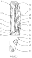
- a fastening loop 10 used in particular for a chin strap of a safety helmet, comprises a latching means 12 male intended to fit together through a first slot 14 for passage in a retaining means 16 female to form a positive locking mechanical connection.
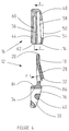
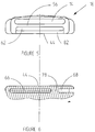
- the male latching means 12 comprises a substantially flat tongue 18 having a rounded front edge 20 delimited by two opposite edges 22, 24 extending parallel to the longitudinal interlocking direction indicated by the arrow F (FIG. 3).
- a U-shaped groove 26 is cut in the tongue 18 so as to constitute an elastic locking lug 28 mounted with limited pivoting around a fictitious transverse axis 30 and perpendicular to the longitudinal interlocking direction F.
- the free end of the lug 28 is provided with a hooking notch 32, and the elasticity effect urges the lug 28 projecting from the upper surface of the tongue 18.
- the tongue 18 of the male latching means 12 is secured opposite the edge 20, to a gripping base 34 provided with two grooves 36, 38 parallel to the imaginary axis 30 and spaced by a crosspiece 40, allowing passage intersecting and adjusting the length of a first strap 42 of the chin strap ( Figure 10).
- the female retaining means 16 is arranged in a hollow button of semi-circular shape, having a flat bottom 44, and a first front surface 46 substantially rectilinear and perpendicular to the bottom 44.
- a second upper surface 48 of the button is slightly rounded and has a orifice 50 of shape combined with that of the locking pin 28.
- the edge 52 of the orifice 50, located in the vicinity of the front surface 46, is provided with a stop 54 capable of cooperating with the catch 32 for hooking the lug 28 in the locked position of the two elements 12, 16 of loop 10 (see Figure 2).
- the internal space of the hollow button is divided by a partition 56 intermediate in a first and a second compartments 58, 60 stepped.
- the partition 56 of separation extends horizontally in a direction parallel to the bottom 44 to the front surface 46 to delimit the first slot 14 for access to the upper compartment 58, and a second slot 62 associated with the lower compartment 60, the latter being arranged between the bottom 44 and the partition 56.
- the two slots 14, 62 are parallel and superimposed in the height direction.
- the bottom 44 is connected to the second upper curved surface 48 of the button by a third semi-cylindrical lateral surface 64 equipped with a third and a fourth slots 66, 68 coplanar with the second slot 62.
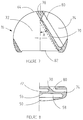
- the lower compartment 60 of the retaining means 16 is itself subdivided by a vertical wall 70 into two adjacent chambers 72, 74 authorizing the V-intersection of a second strap 76 or chin strap (Figure 10).
- the wall 70 is inclined at an acute angle A relative to the median plane of symmetry, extending continuously from the right end of the second slot 62 to a spacer 78 for separating the third and fourth slots 66, 68 ( Figure 7).
- the bottom 44 is pierced by a fifth slot 80 for access to the chamber 74, said slot 80 extending in the vicinity of the wall 70 and along the same inclined direction.
- the wall 82 of the bottom 44 delimiting the second slot 62 for access to the chamber 72 is slightly recessed with respect to the partition 56.
- the two latching and retaining means 12, 16 are produced by molding a plastic material having high mechanical strength.
- the gripping base 34 of the latching means 12 comprises a lower shoulder 84 and an upper stop 86 capable of coming into engagement against the first front surface 46 at the end of the insertion stroke of the latching means 12 male in the means 16 female retainer.
- the thickness of the three slots 62, 66, 68 of the lower compartment 60 is slightly greater than that of the strap 76.
- the female retaining means 16 is connected to one of the sides of the helmet (not shown) by the two strands of the second strap 76.
- the latter is previously placed in the two chambers 72, 74 of the lower compartment 60 of the button hollow.
- the end of the strap 76 is first introduced from the rear into the chamber 72 through the third slot 66 (according to the arrow 6 indicated in FIG. 3), then comes out at the front through the second slot 62, followed by total folding 180 degrees under the outer face of the bottom 44.
- the strap 76 is then reintroduced into the adjacent chamber 74 through the fifth slot 80 from the bottom 44, then out of said chamber 74 through the fourth slot 68 (see FIG. 11).
- the entry and exit of the second strap 76 take place on the side of the third lateral surface 64, and the shape of the V is ensured by multidirectional folding of the strap inside the hollow button.
- the first strap 42 is also placed in the two grooves 36, 38 of the base 34 for gripping the male latching means 12.
- the adjustment of the useful length of the strap 42 can be adjusted according to the morphology of the user.
- the closure of the loop 10 is obtained by the insertion according to arrow F (FIG. 3) of the tongue 18 of the male latching means 12 in the upper compartment 58 of the female retaining means 16.
- the height of the upper compartment 58 is slightly greater than the thickness of the tongue 18, and the latter has a shape combined with the longitudinal section of the compartment 58.
- the catch 32 for hooking the lug 28 comes into contact with the stop 54 of the edge 52, preventing any withdrawal of the male latching means 12, which is locked inside the upper compartment 58.
- the interval separating the wall 82 from the shoulder 84 in the locked position of the buckle 10 allows the passage of the strap 76 at the second slot 62.
- the unlocking of the loop 10 is operated by a manual pushing action on the lug 28 (see arrow F2 in FIG. 2), which is moved against the elastic force towards the inactive position, releasing the notch 32 from the 'locking effect of the stop 54.
- the tongue 18 can then be removed from the upper compartment 58 to ensure the physical separation of the two means 12, 16 from the fixing loop 10.
- the mechanical connection by snap-fastening of the two means 12, 16 of the loop 10, and the V-intersection of the second strap 76 take place in two separate compartments 58, 60 stepped inside the hollow button of the retaining means 16 female.
- the fastening loop 10 of the chin strap therefore has a reduced bulk and improves the comfort and use of the user.
Landscapes
- Helmets And Other Head Coverings (AREA)
- Purses, Travelling Bags, Baskets, Or Suitcases (AREA)
- Emergency Lowering Means (AREA)
- Buckles (AREA)
Applications Claiming Priority (2)
| Application Number | Priority Date | Filing Date | Title |
|---|---|---|---|
| FR9205554 | 1992-05-04 | ||
| FR929205554A FR2690608B1 (fr) | 1992-05-04 | 1992-05-04 | Boucle de fixation pour une jugulaire d'un casque de securite. |
Publications (2)
| Publication Number | Publication Date |
|---|---|
| EP0569302A1 true EP0569302A1 (de) | 1993-11-10 |
| EP0569302B1 EP0569302B1 (de) | 1996-09-25 |
Family
ID=9429569
Family Applications (1)
| Application Number | Title | Priority Date | Filing Date |
|---|---|---|---|
| EP93420161A Expired - Lifetime EP0569302B1 (de) | 1992-05-04 | 1993-04-15 | Befestigungsschnalle für den Kinnriemen eines Schutzhelms |
Country Status (6)
| Country | Link |
|---|---|
| US (1) | US5398390A (de) |
| EP (1) | EP0569302B1 (de) |
| JP (1) | JP3414789B2 (de) |
| DE (1) | DE69304985T2 (de) |
| ES (1) | ES2094510T3 (de) |
| FR (1) | FR2690608B1 (de) |
Cited By (1)
| Publication number | Priority date | Publication date | Assignee | Title |
|---|---|---|---|---|
| CN103040181A (zh) * | 2013-01-08 | 2013-04-17 | 浙江耐特科技有限公司 | 多功能安全帽 |
Families Citing this family (14)
| Publication number | Priority date | Publication date | Assignee | Title |
|---|---|---|---|---|
| US5774956A (en) * | 1997-01-24 | 1998-07-07 | Michaels Of Oregon Co. | High-security buckle |
| GB9805487D0 (en) * | 1998-03-17 | 1998-05-13 | Ici Plc | Plastic material |
| US6662413B2 (en) * | 2002-05-02 | 2003-12-16 | Cosco Management, Inc. | Harness retainer with limited-travel button |
| US8353066B2 (en) | 2006-02-04 | 2013-01-15 | Artisent, Llc | Easily adjusted retention system for helmets |
| US7600268B2 (en) * | 2006-02-04 | 2009-10-13 | Artisent, Inc. | Helmet retention system with improved stability |
| KR101006569B1 (ko) * | 2009-02-24 | 2011-01-07 | 주식회사 에스탑 | 안전모용 내피 고정홀더 |
| DE102011054945B4 (de) * | 2011-10-31 | 2013-06-13 | Anton Pfanner | Gurtverschluss und damit ausgerüsteter Kinnriemen eines Schutzhelms |
| US9433259B2 (en) * | 2013-10-24 | 2016-09-06 | Bell Sports, Inc. | Self-actuating webbing adjuster and helmet strap system including same |
| KR101437643B1 (ko) * | 2013-10-31 | 2014-09-04 | 주식회사 산청 | 헬멧 |
| USD810362S1 (en) | 2015-03-24 | 2018-02-13 | Gentex Corporation | Helmet retention system |
| US10188177B2 (en) * | 2015-08-17 | 2019-01-29 | Bell Sports, Inc. | Friction stop strap adjustor |
| USD999673S1 (en) * | 2019-02-15 | 2023-09-26 | Zedel | Buckle |
| PT115577B (pt) * | 2019-06-14 | 2021-11-25 | Kaiola Design Unipessoal Lda | Chapéu que tem membros de tira de queixo |
| CN113546343A (zh) * | 2021-08-24 | 2021-10-26 | 泰克曼(南京)电子有限公司 | 防护设备及其便携式电动过滤送风机组件 |
Citations (3)
| Publication number | Priority date | Publication date | Assignee | Title |
|---|---|---|---|---|
| SE306441B (de) * | 1967-09-20 | 1968-11-25 | Bengtsson Sigurd W | |
| WO1989001744A1 (en) * | 1987-08-28 | 1989-03-09 | Bil Ab Atlas | Headgear and method to produce the headgear. |
| DE8816545U1 (de) * | 1988-10-05 | 1989-12-07 | Cullmann Handelsgesellschaft für Verbrauchsgüter mbH, 8506 Langenzenn | Verbindungseinrichtung für Gurte bzw. Riemen |
Family Cites Families (2)
| Publication number | Priority date | Publication date | Assignee | Title |
|---|---|---|---|---|
| US4282634A (en) * | 1979-12-21 | 1981-08-11 | Jack Krauss | Buckle |
| US4901373A (en) * | 1988-03-07 | 1990-02-20 | Bell Helmets, Inc. | Helmet retention system with adjustable buckle |
-
1992
- 1992-05-04 FR FR929205554A patent/FR2690608B1/fr not_active Expired - Fee Related
-
1993
- 1993-04-15 ES ES93420161T patent/ES2094510T3/es not_active Expired - Lifetime
- 1993-04-15 EP EP93420161A patent/EP0569302B1/de not_active Expired - Lifetime
- 1993-04-15 DE DE69304985T patent/DE69304985T2/de not_active Expired - Lifetime
- 1993-04-27 JP JP10113393A patent/JP3414789B2/ja not_active Expired - Fee Related
- 1993-04-28 US US08/053,359 patent/US5398390A/en not_active Expired - Lifetime
Patent Citations (3)
| Publication number | Priority date | Publication date | Assignee | Title |
|---|---|---|---|---|
| SE306441B (de) * | 1967-09-20 | 1968-11-25 | Bengtsson Sigurd W | |
| WO1989001744A1 (en) * | 1987-08-28 | 1989-03-09 | Bil Ab Atlas | Headgear and method to produce the headgear. |
| DE8816545U1 (de) * | 1988-10-05 | 1989-12-07 | Cullmann Handelsgesellschaft für Verbrauchsgüter mbH, 8506 Langenzenn | Verbindungseinrichtung für Gurte bzw. Riemen |
Cited By (2)
| Publication number | Priority date | Publication date | Assignee | Title |
|---|---|---|---|---|
| CN103040181A (zh) * | 2013-01-08 | 2013-04-17 | 浙江耐特科技有限公司 | 多功能安全帽 |
| CN103040181B (zh) * | 2013-01-08 | 2015-08-19 | 浙江耐特科技有限公司 | 多功能安全帽 |
Also Published As
| Publication number | Publication date |
|---|---|
| EP0569302B1 (de) | 1996-09-25 |
| DE69304985T2 (de) | 1997-03-13 |
| JP3414789B2 (ja) | 2003-06-09 |
| FR2690608A1 (fr) | 1993-11-05 |
| US5398390A (en) | 1995-03-21 |
| DE69304985D1 (de) | 1996-10-31 |
| ES2094510T3 (es) | 1997-01-16 |
| FR2690608B1 (fr) | 1994-07-29 |
| JPH06294007A (ja) | 1994-10-21 |
Similar Documents
| Publication | Publication Date | Title |
|---|---|---|
| EP0569302B1 (de) | Befestigungsschnalle für den Kinnriemen eines Schutzhelms | |
| FR2665340A1 (fr) | Boucle de jugulaire de casque. | |
| FR2472448A1 (fr) | Ensemble a lame(s) de rasoir muni d'un capuchon-couvercle mobile | |
| EP2138061B1 (de) | Schutzhelm mit perfektioniertem regulierbarem Nackenverschluss | |
| CA2286423C (fr) | Casque de protection et son dispositif d'accrochage de masque respiratoire | |
| EP1277419B1 (de) | Rucksack mit externer Haltevorrichtung | |
| FR2623301A1 (fr) | Dispositif reglable de fixation de lunettes sur un casque de moto | |
| EP2725937B1 (de) | Dehnbare klammer für ein armband, insbesondere ein uhrenarmband | |
| FR2604069A1 (fr) | Boucle de ceinture. | |
| FR2554688A1 (fr) | Chaussure de ski | |
| FR2758246A1 (fr) | Attache d'extremite de ceinture | |
| FR2783679A1 (fr) | Attache de sangle | |
| FR2553978A1 (fr) | Casque de protection, en particulier pour des jeux sportifs | |
| WO2008034603A1 (fr) | Dispositif a sangles pour maintien d'articles dans une valise | |
| FR2691888A1 (fr) | Boîtier muni d'un dispositif de fermeture ne comportant pas d'organe mobile. | |
| FR2948856A1 (fr) | Dispositif de fixation d'une plaque support d'au moins un accessoire sur une cuisse d'un utilisateur. | |
| EP0914781A1 (de) | Faltverschluss für Armbänder | |
| CH667979A5 (en) | Adjustable fastener for bracelet - has curved central plate having groove in which arm of one part slides and locks in notches in groove | |
| EP0799581A1 (de) | Schutzhelm mit an die Kopfgrösse anpassbaren Einstellungselementen | |
| EP1875823A1 (de) | Schnallen mit zwei trennbaren Teilen zur Befestigung eines V-Gurts und ihre Benutzung zur Befestigung eines Schutzhelms | |
| WO2017013620A1 (fr) | Dispositif de connexion pour sangles, objets parties de vetements et accessoires. | |
| EP0553037A1 (de) | Sicherheitshelm mit Vorrichtung zum Befestigen von Zusatzgeräten | |
| EP0486411A1 (de) | Aussengangsicherheitsvorrichtung | |
| WO1983003741A1 (fr) | Boucle de ceinture de securite a loquet de blocage pivotant | |
| FR2550923A1 (fr) | Casque de protection avec un dispositif de reglage de jugulaire |
Legal Events
| Date | Code | Title | Description |
|---|---|---|---|
| PUAI | Public reference made under article 153(3) epc to a published international application that has entered the european phase |
Free format text: ORIGINAL CODE: 0009012 |
|
| AK | Designated contracting states |
Kind code of ref document: A1 Designated state(s): DE ES GB IT |
|
| 17P | Request for examination filed |
Effective date: 19931130 |
|
| 17Q | First examination report despatched |
Effective date: 19950308 |
|
| GRAG | Despatch of communication of intention to grant |
Free format text: ORIGINAL CODE: EPIDOS AGRA |
|
| GRAH | Despatch of communication of intention to grant a patent |
Free format text: ORIGINAL CODE: EPIDOS IGRA |
|
| GRAH | Despatch of communication of intention to grant a patent |
Free format text: ORIGINAL CODE: EPIDOS IGRA |
|
| GRAA | (expected) grant |
Free format text: ORIGINAL CODE: 0009210 |
|
| AK | Designated contracting states |
Kind code of ref document: B1 Designated state(s): DE ES GB IT |
|
| REF | Corresponds to: |
Ref document number: 69304985 Country of ref document: DE Date of ref document: 19961031 |
|
| GBT | Gb: translation of ep patent filed (gb section 77(6)(a)/1977) |
Effective date: 19961101 |
|
| ITF | It: translation for a ep patent filed | ||
| REG | Reference to a national code |
Ref country code: ES Ref legal event code: FG2A Ref document number: 2094510 Country of ref document: ES Kind code of ref document: T3 |
|
| PLBE | No opposition filed within time limit |
Free format text: ORIGINAL CODE: 0009261 |
|
| STAA | Information on the status of an ep patent application or granted ep patent |
Free format text: STATUS: NO OPPOSITION FILED WITHIN TIME LIMIT |
|
| 26N | No opposition filed | ||
| REG | Reference to a national code |
Ref country code: GB Ref legal event code: IF02 |
|
| PGFP | Annual fee paid to national office [announced via postgrant information from national office to epo] |
Ref country code: ES Payment date: 20090508 Year of fee payment: 17 |
|
| PGFP | Annual fee paid to national office [announced via postgrant information from national office to epo] |
Ref country code: IT Payment date: 20090421 Year of fee payment: 17 |
|
| PGFP | Annual fee paid to national office [announced via postgrant information from national office to epo] |
Ref country code: GB Payment date: 20090415 Year of fee payment: 17 |
|
| PGFP | Annual fee paid to national office [announced via postgrant information from national office to epo] |
Ref country code: DE Payment date: 20100430 Year of fee payment: 18 |
|
| GBPC | Gb: european patent ceased through non-payment of renewal fee |
Effective date: 20100415 |
|
| PG25 | Lapsed in a contracting state [announced via postgrant information from national office to epo] |
Ref country code: IT Free format text: LAPSE BECAUSE OF NON-PAYMENT OF DUE FEES Effective date: 20100415 Ref country code: GB Free format text: LAPSE BECAUSE OF NON-PAYMENT OF DUE FEES Effective date: 20100415 |
|
| REG | Reference to a national code |
Ref country code: ES Ref legal event code: FD2A Effective date: 20110715 |
|
| PG25 | Lapsed in a contracting state [announced via postgrant information from national office to epo] |
Ref country code: ES Free format text: LAPSE BECAUSE OF NON-PAYMENT OF DUE FEES Effective date: 20110705 |
|
| PG25 | Lapsed in a contracting state [announced via postgrant information from national office to epo] |
Ref country code: ES Free format text: LAPSE BECAUSE OF NON-PAYMENT OF DUE FEES Effective date: 20100416 |
|
| REG | Reference to a national code |
Ref country code: DE Ref legal event code: R119 Ref document number: 69304985 Country of ref document: DE |
|
| REG | Reference to a national code |
Ref country code: DE Ref legal event code: R119 Ref document number: 69304985 Country of ref document: DE |
|
| PG25 | Lapsed in a contracting state [announced via postgrant information from national office to epo] |
Ref country code: DE Free format text: LAPSE BECAUSE OF NON-PAYMENT OF DUE FEES Effective date: 20111031 |