EP0569435B1 - Filtereinsatz für behälter - Google Patents
Filtereinsatz für behälter Download PDFInfo
- Publication number
- EP0569435B1 EP0569435B1 EP92903772A EP92903772A EP0569435B1 EP 0569435 B1 EP0569435 B1 EP 0569435B1 EP 92903772 A EP92903772 A EP 92903772A EP 92903772 A EP92903772 A EP 92903772A EP 0569435 B1 EP0569435 B1 EP 0569435B1
- Authority
- EP
- European Patent Office
- Prior art keywords
- filter insert
- filter
- plunger
- liquid
- container
- Prior art date
- Legal status (The legal status is an assumption and is not a legal conclusion. Google has not performed a legal analysis and makes no representation as to the accuracy of the status listed.)
- Expired - Lifetime
Links
- 239000007788 liquid Substances 0.000 claims abstract description 31
- 241001122767 Theaceae Species 0.000 claims abstract description 12
- 239000000463 material Substances 0.000 claims abstract description 7
- 229920003023 plastic Polymers 0.000 claims abstract description 6
- 239000004033 plastic Substances 0.000 claims abstract description 6
- 238000000605 extraction Methods 0.000 claims description 7
- 238000001914 filtration Methods 0.000 claims description 4
- 230000000063 preceeding effect Effects 0.000 claims 3
- 238000001802 infusion Methods 0.000 description 17
- 238000000926 separation method Methods 0.000 description 10
- 238000003825 pressing Methods 0.000 description 6
- 239000000706 filtrate Substances 0.000 description 3
- 238000005452 bending Methods 0.000 description 2
- 238000004140 cleaning Methods 0.000 description 2
- 230000008878 coupling Effects 0.000 description 2
- 238000010168 coupling process Methods 0.000 description 2
- 238000005859 coupling reaction Methods 0.000 description 2
- 230000001419 dependent effect Effects 0.000 description 2
- 230000002349 favourable effect Effects 0.000 description 2
- 239000011521 glass Substances 0.000 description 2
- XLYOFNOQVPJJNP-UHFFFAOYSA-N water Substances O XLYOFNOQVPJJNP-UHFFFAOYSA-N 0.000 description 2
- 229920003266 Leaf® Polymers 0.000 description 1
- 230000000694 effects Effects 0.000 description 1
- 238000012986 modification Methods 0.000 description 1
- 230000004048 modification Effects 0.000 description 1
- 238000002360 preparation method Methods 0.000 description 1
- 230000003014 reinforcing effect Effects 0.000 description 1
- 239000002699 waste material Substances 0.000 description 1
Images


Classifications
-
- A—HUMAN NECESSITIES
- A47—FURNITURE; DOMESTIC ARTICLES OR APPLIANCES; COFFEE MILLS; SPICE MILLS; SUCTION CLEANERS IN GENERAL
- A47J—KITCHEN EQUIPMENT; COFFEE MILLS; SPICE MILLS; APPARATUS FOR MAKING BEVERAGES
- A47J31/00—Apparatus for making beverages
- A47J31/18—Apparatus in which ground coffee or tea-leaves are immersed in the hot liquid in the beverage container
- A47J31/20—Apparatus in which ground coffee or tea-leaves are immersed in the hot liquid in the beverage container having immersible, e.g. rotatable, filters
-
- A—HUMAN NECESSITIES
- A47—FURNITURE; DOMESTIC ARTICLES OR APPLIANCES; COFFEE MILLS; SPICE MILLS; SUCTION CLEANERS IN GENERAL
- A47G—HOUSEHOLD OR TABLE EQUIPMENT
- A47G19/00—Table service
- A47G19/12—Vessels or pots for table use
- A47G19/16—Tea infusers, e.g. infusing bags, egg-shaped infuses
Definitions
- the present invention relates to a filter insert for containers, in particular tea pots, where a certain dwelling time should be secured for the filter pulp in a liquid withheld in the container, the insert consisting of a preferably circular cylindrical filter unit, extending downwards from the top of the container at least reach down below the surface of the liquid in the container when being filled, and where at least one plunger shaft with a plunger sliding in a plunger guide is extending axially through the upper part, where the plunger is provided with a rim flange and can be moved to the bottom of the filter insert.
- Such filter inserts are already known, for instance from FR-A-1.196.574, where both plunger and the bottom of the filter insert are perforated with a view to the free passage of the liquid, while tea leafs are kept inside between the plunger and the bottom of the filter inset.
- the plunger is provided with a reinforcing rim rib, extending towards the bottom of the filter insert.
- the volume, in which the infusion takes place, is in this filter insert limited to between the lower third and half of the filter insert volume, which is insufficient for a complete infusion.
- the infusion can not be stopped after pressing down the plunger, as an infusion still takes place through the perforations in the bottom of the filter insert and in the plunger.
- the plunger during the infusion shall be kept in its top position, e.g. through friction, failing which it will sink and limit the infusion volume further.
- filter inserts for instance in the form of a paper filter, which, fastened in a fixture, hangs down from the top of the container.
- This filter insert works satisfactory, but encumbered with those inconveniences, that the volume of infusion is relatively small, and that the filter insert after expiration of the extraction time must be taken up from the liquid so as to prevent further infusion between the liquid and the filter pulp, after which the larger part of the liquid contained in the filter pulp normally should be squeezed out from the filter pulp and deposited after that.
- This can not always take place, as both the pressing and the deposit possibillities can be limited in time and locality, and besides, the mechanical strength of the paper material is limited.
- the need for pressing the filter pulp has arizen from, partly, the desire to reduce waste or, partly, to prevent dripping of liquid on the way between the container and the place of deposit.
- the invention is therefore based on the object to provide the largest possible volume of infusion, to separate filter pulp and liquid in such a way, that after the separation no infusion takes place between filter pulp and liquid, and to eliminate the need for external deposit, while the largest possible quantity of liquid is pressed from the filter pulp.
- the filter insert is divided in at least two sections, a bottom part and a top part, where the bottom part consists of a material, for instance plastics, which is impermeable to the liquid, and the top part mainly consists of a material permeable to the liquid, for instance a wire screen, which can keep the filter pulp, and where the plunger also is impermeable and vaulted upwards so, that the central area is higher than the circumference area, which is made with an upright rim flange.
- the bottom part consists of a material, for instance plastics, which is impermeable to the liquid
- the top part mainly consists of a material permeable to the liquid, for instance a wire screen, which can keep the filter pulp
- the plunger also is impermeable and vaulted upwards so, that the central area is higher than the circumference area, which is made with an upright rim flange.
- the filter insert With the embodiment of the filter insert according to the invention the following advantages are obtained in, that an effective separation between filter pulp and liquid is provided, that this separation appears by a simple movement of the plunger from one extreme position to the other, and that the filtrate is accessible immediately after the separation, without first removing the filter pulp from the container and thereby risking drops and splash liquid on the way between the container and the place of deposit for the filter pulp. Moreover, the largest possible infusion volume is secured by having the plunger floating on top of the liquid during the infusion as a result partly of the vaulted embodiment and partly of the upright rim flange. After the pressing down of the plunger it remains in the bottom position, as it after the submersion in the liquid loses its buoyancy capacity.
- the top part consists of two parts, namely a filtering unit and a lid part, in which the plunger guide is placed.
- the lid part can be elaborated so, that the top part covers the filter insert totally and simultaneously operates as a lid for the extraction container.
- the permeable part of the filter insert is made with a releasable connection both to the bottom part and to the lid part, where the filter insert is equipped with a section preferably of plastics provided with grip-means suiting corresponding grip-means in the corresponding part of the bottom part or the lid part.
- the gripping means can, favourably, be made as screw threads, as bayonet socket or as snap-locks. It should be observed, that the wire screen is not influenced by pressure or bending forces, for which reason the assembling and the disassembling of the gripping means shall take place with the least possible exercion of force.
- a filter insert according to the invention can be used in an arbitrary extraction container dependent of its opening diameter, if only the precondition is observed, that the wire screen during the infusion phase can reach totally down under the surface of the liquid in the container.
- FIG. 1 shows a tea pot of glass equipped with a filter insert 1 according to the invension.
- the filter insert 1 consists of a bottom part 2 and a top part 3 consisting of a wire screen 3a, which is fastened to a lid part 6 with the help of a not specificly shown coupling part.
- a bushing 7 is fastened serving as guidance for a plunger shaft 4.
- a handle 10 is placed, and at the bottom of the plunger shaft 4 a plunger 5 is placed the diameter of which corresponds to the inner diameter of the wire screen 3a.
- FIG 2 a partly sectional view of the filter insert 1 is shown, from which it can be seen, how the top part 3 is fastened to the bottom part 2.
- a coupling part is fastened, which is equipped with grip- or locking means 8 suiting corresponding grip- or locking means 9 in the corresponding part of the bottom part 2.
- the embodiment of the grip- or locking means 8, 9 is only drafted, as arbitrary embodiments can be used for these grip- or locking means 8, 9.
- the grip- or locking means 8, 9 shown in figure 2 these have the form of an embossment 8 and a corresponding groove 9, where the embossment 8 is brought into engagement in the groove 9 by a snap effect.
- the grip- or locking means can also be in the form of screw threads or as a bayonet socket.
- Figure 2 also shows a partly section through the plunger 5, where can be seen, that the upright rim 5a has a height, which in this embodiment is nearly half as high as the vault of the plunger.
- the height of the rim is determinative for the buoyancy of the plunger and shall just be adjusted to the total weight of plunger 5, plunger shaft 4 and handle 10.
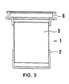
- Figure 3 shows a filter insert 1 in sectional view, where, however, no grip- or locking means 8, 9 are shown, as a separation between the bottom part 2 and the top part 3 is not absolutely necessary in order to obtain the purpose of the invention.
- the lid part 6 on the top part 3 is formed so, that it has a bushing 7, which guides the plunger shaft 4.
- the lid part 6 and the plunger shaft 4 are assembled in a unit, which can be removed during the preparation of the tea.
- a handle 10 is placed, as earlier mentioned, in order to ease the operation of the plunger 5 and the plunger shaft 4.
- the handle 10 which shall not be more elaborated, can be formed in an arbitrary way, as only utilizational and/or estetical considerations should be taken into account.
- the handle 10 could further contain a not shown clock, which appropriately could be operated by a battery or by thermo-electical elements driven by temperature differences. This clock could hereby measure the duration of the infusion phase, so that the correct duration of this phase culd be secured.
- Some tea-sorts need an extraction time of 5 minutes and other tea-sorts, icluding Keemun tea, need extraction time of 15 minutes.
- the presence of the clock is not essential to the filter insert, but it eases the use of a tea pot with a filter insert according to the invention, when the use takes place far from normal kitchen timers or the like.
- the proces itself by using the filter insert is not much different from the proces known from other filter types, until the end of the infusion phase.
- the plunger 5 is placed in the top of the wire screen floating so as to secure, that all the contents of the filter is below the surface of the water.
- the lid is placed in the lid part.
- a pressure downwards should be exerted on the handle 10 with the filter insert according to the invention, whereby the plunger 5 is brought axially through the filter insert 1 down towards the bottom part 2, where the plunger 5 and the bottom part 2 together incapsulate the filter pulp after the filtrate at the same time has been pressed out from the filter pulp.
- the following advantages are obtained in, that an effective separation between filter pulp and liquid is provided, that this separation appears by a simple movement of the plunger from one extreme position to the other, and that the filtrate is accessible immediately after the separation, without first removing the filter pulp from the container and thereby risking drops and splash liquid on the way between the container and the place of deposit for the filter pulp.
Landscapes
- Engineering & Computer Science (AREA)
- Food Science & Technology (AREA)
- Apparatus For Making Beverages (AREA)
- Piezo-Electric Or Mechanical Vibrators, Or Delay Or Filter Circuits (AREA)
- Separation Using Semi-Permeable Membranes (AREA)
- Food-Manufacturing Devices (AREA)
- Centrifugal Separators (AREA)
- Apparatus Associated With Microorganisms And Enzymes (AREA)
- Packages (AREA)
Claims (9)
- Filtereinsatz (1) für Behälter, insbesondere Teekrüge, bei denen eine gewisse Verweilzeit des Filterschlamms in einer sich im Behälter befindlichen Flüssigkeit gewährleistet sein soll, wobei der Einsatz aus einer vorzugsweise kreisförmigen zylindrischen Filtereinheit (1) besteht, dis sich von der Spitze des Behälters nach unten erstreckt und mindestens bis unter die Oberfläche der sich im Behälter befindlichen Flüssigkeit hinabreicht, wenn dieser gefüllt ist, und wobei mindestens ein in einer Støpselführung (7) gleitender Stöpselstiel (4) mit einem Stöpsel (5) sich axial durch den Oberteil (3) erstreckt, wobei der Stöpsel (5) mit einem Randflansch (5a) versehen ist und bis auf den Boden des Filtereinsatzes (1) bewegt werden kann, dadurch gekennzeichnet, daß der Filtereinsatz (1) in minddestens zwei Teile geteilt ist, einem Unterteil (2) und einem Oberteil (3), wobei der Unterteil (2) aus Material, zum Beispiel Kunststoff, besteht, das für die Flüssigkeit undurchlässig ist, und der Oberteil (3) im wesentlichen aus Material besteht, das für die Flüssigkeit durchlässig ist, zum Beispiel ein Drahtsieb (3a), welches den Filterschlæamm aufnehmen kann, und wobei der Stöpsel (5) ebenfalls undurchlässig und derart nach oben gewölbt ist, daß sein Mittelbereich höher liegt als sein Periferiebereich, welcher aus einem aufrecht stehenden Randflansch (5a) besteht.
- Filtereinsatz nach Anspruch 1, dadurch gekennzeichnet, daß der Oberteil (3) aus zwei Teilen besteht, das heißt aus einer Filtereinheit (3a) und einem Deckelteil (6), in welchem die Stöpselführung (7) angeordnet ist.
- Filtereinsatz nach Anspruch 1 oder 2, dadurch gekennzeichnet, daß der Deckelteil derart ausgebildet ist, daß der Oberteil (3) den Filtereinsatz (1) vollständig abgedeckt und gleichzeitig als Deckel für den Extraktionsbehälter dient.
- Filtereinsatz nach einem der Ansprüche 1 bis 3, dadurch gekennzeichnet, daß der durchlässige Teil (3a) des Filtereinsatzes (1) mit einer lösbaren Verbindung mit dem Unterteil (2) und dem Deckelteil (6) ausgestattet ist.
- Filtereinsatz nach einem der Ansprüche 1 bis 3, dadurch gekennzeichnet, daß der durchlässige Teil (3a) des Filtereinsatzes (1) einen vorzugsweise aus Kunststoff bestehenden Teil (3b) aufweist, der mit Arretiermittel (8) versehen ist, die in entsprechenden Arretiermittel (9) des entsprechenden Teils des Unterteils (2) oder des Deckelteils (6) passen.
- Filtereinsatz nach Anspruch 5, dadurch gekennzeichnet, daß die Arretiermittel (8,9) als Schraubengewinde ausgebildet sind.
- Filtereinsatz nach Anspruch 5, dadurch gekennzeichnet, daß die Arretiermittel (8,9) als Bayonnetverschlüsse ausgebildet sind.
- Filtereinsatz nach Anspruch 5, dadurch gekennzeichnet, daß die Arretiermittel (8,9) als Schnappverschlüsse ausgebildet sind.
- Filtereinsatz nach einem der Ansprüche 1 bis 8, dadurch gekennzeichnet, daß die Höhe des Randflansches (5a) nahezu gleich groß wie die Höhe des Gewölbes ist.
Applications Claiming Priority (3)
| Application Number | Priority Date | Filing Date | Title |
|---|---|---|---|
| DK176/91 | 1991-02-01 | ||
| DK017691A DK17691A (da) | 1991-02-01 | 1991-02-01 | Filterindsats til beholdere |
| PCT/DK1992/000033 WO1992013475A1 (en) | 1991-02-01 | 1992-01-31 | Filter insert for containers |
Publications (2)
| Publication Number | Publication Date |
|---|---|
| EP0569435A1 EP0569435A1 (de) | 1993-11-18 |
| EP0569435B1 true EP0569435B1 (de) | 1995-01-18 |
Family
ID=8090631
Family Applications (2)
| Application Number | Title | Priority Date | Filing Date |
|---|---|---|---|
| EP92610008A Pending EP0497726A1 (de) | 1991-02-01 | 1992-01-31 | Filtereinsatz für Behälter |
| EP92903772A Expired - Lifetime EP0569435B1 (de) | 1991-02-01 | 1992-01-31 | Filtereinsatz für behälter |
Family Applications Before (1)
| Application Number | Title | Priority Date | Filing Date |
|---|---|---|---|
| EP92610008A Pending EP0497726A1 (de) | 1991-02-01 | 1992-01-31 | Filtereinsatz für Behälter |
Country Status (14)
| Country | Link |
|---|---|
| US (1) | US5453189A (de) |
| EP (2) | EP0497726A1 (de) |
| JP (1) | JP3011766B2 (de) |
| AT (1) | ATE117182T1 (de) |
| AU (1) | AU660655B2 (de) |
| CA (1) | CA2100455C (de) |
| CH (1) | CH684154A5 (de) |
| DE (1) | DE69201237T2 (de) |
| DK (2) | DK17691A (de) |
| ES (1) | ES2069991T3 (de) |
| GR (1) | GR3015856T3 (de) |
| IL (1) | IL100840A0 (de) |
| NZ (1) | NZ270328A (de) |
| WO (1) | WO1992013475A1 (de) |
Cited By (2)
| Publication number | Priority date | Publication date | Assignee | Title |
|---|---|---|---|---|
| DE10149848B4 (de) * | 2001-10-10 | 2006-05-04 | Klaus Kaiser | Filter zur Zubereitung eines Getränks sowie Behälter mit einem derartigen Filter |
| USD536205S1 (en) | 2004-05-21 | 2007-02-06 | Eva Denmark A/S | Teapot with a piston filter assembly |
Families Citing this family (45)
| Publication number | Priority date | Publication date | Assignee | Title |
|---|---|---|---|---|
| GB9513572D0 (en) * | 1995-07-04 | 1995-09-06 | Ag Patents Ltd | Infusion container |
| US5753117A (en) * | 1996-06-05 | 1998-05-19 | Fleetguard, Inc. | Replaceable filter element and snap-on filter lid assembly |
| AU6786296A (en) * | 1996-09-10 | 1998-04-02 | Pi-Design Ag | Display means for time and temperature in apparatus for preparing hot or cold drinks |
| US5806408A (en) * | 1996-11-01 | 1998-09-15 | Debacker; Johanna N. | Beverage brewing device |
| US5927180A (en) * | 1997-02-19 | 1999-07-27 | Russo; Thomas L | Beverage flow pot |
| WO1999026843A1 (en) | 1997-11-26 | 1999-06-03 | Cris Hammond | Beverage infuser |
| US6283013B1 (en) | 1998-01-09 | 2001-09-04 | Hamilton Beach/Proctor-Silex, Inc. | Tea steeper for coffeemaker |
| US5935435A (en) * | 1998-04-20 | 1999-08-10 | Hasler; James J. | Paint can strainer |
| DE69900935D1 (de) | 1998-12-18 | 2002-04-04 | Unilever Nv | Brühsystem |
| DE29902992U1 (de) | 1999-02-19 | 1999-10-21 | Riensch & Held (GmbH & Co), 21035 Hamburg | Filtereinsatz |
| WO2003031064A1 (en) * | 2001-10-12 | 2003-04-17 | Becton, Dickinson And Company | Method and apparatus for transporting biological samples |
| JP4303592B2 (ja) * | 2001-10-12 | 2009-07-29 | ベクトン・ディキンソン・アンド・カンパニー | 生体試料を輸送する方法及びバスケット装置 |
| US6821541B2 (en) | 2002-06-03 | 2004-11-23 | Sin Hang Lee | Anaerobic tea steeper and method of use |
| WO2005023067A1 (ja) * | 2003-09-02 | 2005-03-17 | Cherry Terrace Inc. | 液体中の浮遊物から成分を抽出する抽出器 |
| US7240610B2 (en) * | 2004-03-10 | 2007-07-10 | Ihc Invest, Inc. | Method and apparatus for infusing a liquid with a flavoring or a scent |
| US7213507B2 (en) * | 2004-03-12 | 2007-05-08 | Meyer Intellectual Properties Limited | Infusion beverage brewing system |
| NL1026068C2 (nl) | 2004-04-28 | 2005-10-31 | Sara Lee De Nv | Pad van het eventueel soepele type en samenstel van een houder en een dergelijke pad. |
| US7484457B2 (en) * | 2005-04-06 | 2009-02-03 | Henderson Michael W | Method and apparatus for removing grease and excess liquid from meat |
| US9999314B1 (en) * | 2005-04-18 | 2018-06-19 | Bean Logik, Llc | Cold brew beverage brewing systems |
| US12318032B2 (en) | 2005-04-18 | 2025-06-03 | Bl Patents, Llc | Cold brew beverage brewing systems |
| USD558510S1 (en) * | 2005-07-20 | 2008-01-01 | Pi-Design, Ag | Teapot |
| CA114056S (en) * | 2005-07-22 | 2007-04-30 | Pi Design Ag | Teapot |
| JP4923061B2 (ja) | 2006-01-20 | 2012-04-25 | ピーアイ デザイン アーゲー | フィルタインサート |
| USD566455S1 (en) * | 2006-02-27 | 2008-04-15 | Pi-Design Ag | Cast iron teapot |
| CA119603S (en) * | 2006-09-20 | 2008-01-11 | Pi Design Ag | Teapot |
| CA120447S (en) * | 2006-10-31 | 2008-01-25 | Pi Design Ag | Tea pot |
| CA123941S (en) * | 2007-07-04 | 2008-12-01 | Pi Design Ag | Tea pot |
| USD584100S1 (en) * | 2007-08-07 | 2009-01-06 | Meyer Intellectual Properties Limited | Lidded teapot |
| USD594268S1 (en) * | 2007-12-12 | 2009-06-16 | Pi-Design, Ag | Teapot |
| GB2457074B (en) * | 2008-02-01 | 2012-02-22 | David Richard Birch | Tea pot and a tea pot having a tea filter |
| US20090202691A1 (en) * | 2008-02-11 | 2009-08-13 | Derek Gauger | Coffee making apparatus and method |
| AU2009221646B2 (en) * | 2008-03-06 | 2015-03-19 | Breville Pty Limited | Semi-automatic tea maker |
| CA2778996C (en) | 2009-11-02 | 2016-07-05 | Pi-Design Ag | Tea maker with closable pouring opening |
| USD645290S1 (en) * | 2009-12-29 | 2011-09-20 | Pi-Design Ag | Coffee and tea maker |
| US8313644B2 (en) * | 2010-01-13 | 2012-11-20 | OZOlab | Bottle with an integrated filtration assembly that is manually operated using a plunger |
| USD679538S1 (en) * | 2012-03-09 | 2013-04-09 | Brian Melzer | Tea pot |
| US9089239B2 (en) | 2013-02-28 | 2015-07-28 | Planetary Design | Infuser with solid region to selectively stop infusion and vessel for said infuser |
| US20150208853A1 (en) * | 2014-01-28 | 2015-07-30 | Epoca International, Inc. | Infusion Core with Muddler |
| USD746092S1 (en) * | 2014-07-28 | 2015-12-29 | Epoca International, Inc. | Popcorn popper |
| USD802979S1 (en) * | 2015-09-04 | 2017-11-21 | Epoca International, Inc. | Popcorn popper |
| US11278825B2 (en) * | 2018-11-21 | 2022-03-22 | ModernMilk Co. | Press assembly for plant-based milk |
| US11825974B1 (en) * | 2020-03-01 | 2023-11-28 | Michael O. Murphy | Expandable strainer insert for bottles |
| US12127703B2 (en) * | 2020-08-31 | 2024-10-29 | Adrian Rivera | Liquid infusion device |
| US11707153B2 (en) * | 2021-02-21 | 2023-07-25 | Todd Ewing | Liquid filtering press |
| DE102022109660A1 (de) * | 2022-04-21 | 2023-10-26 | Pi-Design Ag | Filtereinsatz für eine Aufgussvorrichtung zum Zubereiten von Getränken, insbesondere von Kaffee oder Tee sowie Aufgussvorrichtung mit einem derartigen Filtereinsatz |
Family Cites Families (35)
| Publication number | Priority date | Publication date | Assignee | Title |
|---|---|---|---|---|
| US323780A (en) * | 1885-08-04 | Coffee-strainer | ||
| BE554405A (de) * | ||||
| US561921A (en) * | 1896-06-09 | Tea-infuser | ||
| BE548225A (de) * | ||||
| GB190603719A (en) * | 1906-02-15 | 1906-09-20 | Robert Smith | Improvements in and connected with Tea Infusers and Strainers. |
| FR419796A (fr) * | 1910-08-27 | 1911-01-14 | Etablissements J-J Carnaud Et Forges De Basse-Indr | Cafetière |
| US1098799A (en) * | 1913-03-17 | 1914-06-02 | Eddie O Higdon | Liquid-percolator. |
| US1168544A (en) * | 1913-12-17 | 1916-01-18 | Harvey N Newlin | Coffee and tea strainer. |
| US1268858A (en) * | 1917-03-28 | 1918-06-11 | George G Lewis | Beverage-urn. |
| US1572861A (en) * | 1925-07-27 | 1926-02-09 | Larrey Elisa | Rotary percolator |
| GB297244A (en) * | 1927-11-22 | 1928-09-20 | Robert More Mccallum | Improvements in tea pots and the like having infusers |
| US1797672A (en) * | 1928-04-02 | 1931-03-24 | Attilio Calimani | Apparatus for preparing infusions, particularly for preparing coffee |
| US1887848A (en) * | 1928-11-28 | 1932-11-15 | Peirce John Royden | Coffee brewing device |
| GB314445A (en) * | 1929-06-27 | 1930-04-10 | Trude Carstens | Device for infusing beverages |
| US1873023A (en) * | 1929-07-13 | 1932-08-23 | Peirce John Royden | Coffee brewing device |
| US1767915A (en) * | 1929-08-26 | 1930-06-24 | John W Bugg | Percolator and strainer |
| US1984047A (en) * | 1933-06-10 | 1934-12-11 | Thieme Otto | Beverage maker and method |
| US2093980A (en) * | 1936-07-22 | 1937-09-21 | Linger Nellie Victoria | Electric teapot |
| US2401529A (en) * | 1940-05-29 | 1946-06-04 | Varney Justin Arnold | Infusion apparatus |
| US2338251A (en) * | 1943-02-08 | 1944-01-04 | Makino William Megumu | Coffee or tea pot |
| GB673081A (en) * | 1949-05-24 | 1952-06-04 | Duncan Tucker Tottenham Ltd | Improvements in or relating to opening and closing mechanism for roof ventilators, particularly for use in glass houses |
| GB755614A (en) * | 1953-08-05 | 1956-08-22 | Thomas Traill Maclean | Paint strainer |
| US2808775A (en) * | 1954-06-17 | 1957-10-08 | Gen Mills Inc | Combination beverage maker |
| FR1196574A (fr) * | 1957-06-04 | 1959-11-25 | Dispositif d'infusion utilisable pour préparer du thé et des boissons analogues | |
| US3174424A (en) * | 1961-03-31 | 1965-03-23 | Youngstown Steel Door Co | Beverage brewing apparatus |
| US3324787A (en) * | 1965-03-04 | 1967-06-13 | Corning Glass Works | Infuser for tea leaves |
| DE6931252U (de) * | 1969-08-06 | 1969-12-11 | Jacobs Joh & Co | Behaelter zur zubereitung von getraenken. |
| US3592126A (en) * | 1969-12-19 | 1971-07-13 | Gen Electric | Coffeemaker filter |
| US3669694A (en) * | 1971-03-30 | 1972-06-13 | Sunbeam Corp | Percolator coffee basket and filter assembly |
| SE373743B (de) * | 1974-05-20 | 1975-02-17 | R O Winberg | |
| DE2551899A1 (de) * | 1975-11-19 | 1977-06-02 | Korf | Kaffee-schnellpressfilter |
| GB2070917A (en) * | 1980-01-22 | 1981-09-16 | Howitt G | Preparation of beverages |
| DE3715519A1 (de) * | 1987-05-09 | 1988-11-17 | Jacobs Suchard Gmbh | Aufsatzfilter fuer die herstellung von kaffee-getraenken |
| DE69013577T2 (de) * | 1989-06-07 | 1995-03-02 | Japan I P Co Ltd | Filtervorrichtung. |
| USD343759S (en) | 1991-07-30 | 1994-02-01 | Pi-Design Ag | Teapot |
-
1991
- 1991-02-01 DK DK017691A patent/DK17691A/da not_active Application Discontinuation
-
1992
- 1992-01-29 NZ NZ270328A patent/NZ270328A/en not_active IP Right Cessation
- 1992-01-31 AU AU12225/92A patent/AU660655B2/en not_active Expired
- 1992-01-31 CA CA002100455A patent/CA2100455C/en not_active Expired - Lifetime
- 1992-01-31 WO PCT/DK1992/000033 patent/WO1992013475A1/en not_active Ceased
- 1992-01-31 AT AT92903772T patent/ATE117182T1/de not_active IP Right Cessation
- 1992-01-31 ES ES92903772T patent/ES2069991T3/es not_active Expired - Lifetime
- 1992-01-31 EP EP92610008A patent/EP0497726A1/de active Pending
- 1992-01-31 DK DK92903772.9T patent/DK0569435T3/da active
- 1992-01-31 JP JP4503930A patent/JP3011766B2/ja not_active Expired - Fee Related
- 1992-01-31 EP EP92903772A patent/EP0569435B1/de not_active Expired - Lifetime
- 1992-01-31 IL IL100840A patent/IL100840A0/xx not_active IP Right Cessation
- 1992-01-31 CH CH3091/92A patent/CH684154A5/de not_active IP Right Cessation
- 1992-01-31 DE DE69201237T patent/DE69201237T2/de not_active Expired - Lifetime
-
1993
- 1993-07-30 US US08/094,037 patent/US5453189A/en not_active Expired - Lifetime
-
1995
- 1995-04-18 GR GR950400988T patent/GR3015856T3/el unknown
Cited By (2)
| Publication number | Priority date | Publication date | Assignee | Title |
|---|---|---|---|---|
| DE10149848B4 (de) * | 2001-10-10 | 2006-05-04 | Klaus Kaiser | Filter zur Zubereitung eines Getränks sowie Behälter mit einem derartigen Filter |
| USD536205S1 (en) | 2004-05-21 | 2007-02-06 | Eva Denmark A/S | Teapot with a piston filter assembly |
Also Published As
| Publication number | Publication date |
|---|---|
| CA2100455C (en) | 2004-11-16 |
| AU1222592A (en) | 1992-09-07 |
| CA2100455A1 (en) | 1992-08-02 |
| IL100840A0 (en) | 1992-09-06 |
| CH684154A5 (de) | 1994-07-29 |
| JP3011766B2 (ja) | 2000-02-21 |
| DE69201237T2 (de) | 1995-08-31 |
| EP0569435A1 (de) | 1993-11-18 |
| DK17691D0 (da) | 1991-02-01 |
| DK17691A (da) | 1991-09-11 |
| WO1992013475A1 (en) | 1992-08-20 |
| ES2069991T3 (es) | 1995-05-16 |
| EP0497726A1 (de) | 1992-08-05 |
| US5453189A (en) | 1995-09-26 |
| GR3015856T3 (en) | 1995-07-31 |
| DE69201237D1 (de) | 1995-03-02 |
| DK0569435T3 (da) | 1995-05-22 |
| AU660655B2 (en) | 1995-07-06 |
| NZ270328A (en) | 1998-03-25 |
| JPH06505168A (ja) | 1994-06-16 |
| ATE117182T1 (de) | 1995-02-15 |
Similar Documents
| Publication | Publication Date | Title |
|---|---|---|
| EP0569435B1 (de) | Filtereinsatz für behälter | |
| EP0032850B1 (de) | Herstellung von Getränken | |
| US4908222A (en) | Microwave brewing apparatus and method | |
| US5943946A (en) | Infusing device for a beverage | |
| US6283013B1 (en) | Tea steeper for coffeemaker | |
| US4211156A (en) | Apparatus for making a coffee beverage | |
| US5913962A (en) | Espresso brewing-head unit | |
| US4843954A (en) | Tea making machine | |
| WO1997001981A1 (en) | Infusion container | |
| KR20070119661A (ko) | 특히 음료수인 액체 제품을 생산하기 위한 장치와 일회용캡슐 | |
| US7028606B2 (en) | Citrus fruit juice separator with pouring accessory | |
| US20200121116A1 (en) | Filtering receptacle and method of using it | |
| AU2016354347B2 (en) | Collecting container for collecting insoluble material used during the preparation a beverages, and infusion device comprising such a collecting container | |
| US5852966A (en) | Reusable coffee brewing filter | |
| EP4491066A1 (de) | Tauchbrühvorrichtung und -verfahren | |
| KR101720015B1 (ko) | 드립커피 제조를 위한 커피 드립퍼 | |
| CN119212594A (zh) | 用于制备饮料,特别是咖啡或茶的输注装置的过滤器插入件,以及包括这类过滤器插入件的输注装置 | |
| JPH01259810A (ja) | コーヒ又はティーから成る芳香抽出物を製造する装置 | |
| US2338251A (en) | Coffee or tea pot | |
| WO2004026090A1 (en) | A piston for a piston jug for beverages | |
| KR200147417Y1 (ko) | 주전자 뚜껑 | |
| IT202000008380A1 (it) | Accessorio per il riempimento di caffettiere e assieme contenitore comprendente l’accessorio | |
| JPH0337548Y2 (de) | ||
| JPH081708Y2 (ja) | 飲料抽出装置 | |
| JPWO2005023067A1 (ja) | 液体中の浮遊物から成分を抽出する抽出器 |
Legal Events
| Date | Code | Title | Description |
|---|---|---|---|
| PUAI | Public reference made under article 153(3) epc to a published international application that has entered the european phase |
Free format text: ORIGINAL CODE: 0009012 |
|
| 17P | Request for examination filed |
Effective date: 19930707 |
|
| AK | Designated contracting states |
Kind code of ref document: A1 Designated state(s): AT BE CH DE DK ES FR GB GR IT LI LU NL SE |
|
| RBV | Designated contracting states (corrected) |
Designated state(s): AT BE CH DE DK ES FR GB GR IT LI LU NL PT SE |
|
| 17Q | First examination report despatched |
Effective date: 19940526 |
|
| XX | Miscellaneous (additional remarks) |
Free format text: VERBUNDEN MIT 92610008.2/0497726 (EUROPAEISCHE ANMELDENUMMER/VEROEFFENTLICHUNGSNUMMER) DURCH ENTSCHEIDUNG VOM 21.02.94. |
|
| GRAA | (expected) grant |
Free format text: ORIGINAL CODE: 0009210 |
|
| AK | Designated contracting states |
Kind code of ref document: B1 Designated state(s): AT BE CH DE DK ES FR GB GR IT LI LU NL PT SE |
|
| PG25 | Lapsed in a contracting state [announced via postgrant information from national office to epo] |
Ref country code: LI Effective date: 19950118 Ref country code: CH Effective date: 19950118 |
|
| REF | Corresponds to: |
Ref document number: 117182 Country of ref document: AT Date of ref document: 19950215 Kind code of ref document: T |
|
| XX | Miscellaneous (additional remarks) |
Free format text: VERBUNDEN MIT 92610008.2/0497726 (EUROPAEISCHE ANMELDENUMMER/VEROEFFENTLICHUNGSNUMMER) DURCH ENTSCHEIDUNG VOM 21.02.94. |
|
| REF | Corresponds to: |
Ref document number: 69201237 Country of ref document: DE Date of ref document: 19950302 |
|
| ITF | It: translation for a ep patent filed | ||
| REG | Reference to a national code |
Ref country code: CH Ref legal event code: PL |
|
| ET | Fr: translation filed | ||
| REG | Reference to a national code |
Ref country code: ES Ref legal event code: FG2A Ref document number: 2069991 Country of ref document: ES Kind code of ref document: T3 |
|
| REG | Reference to a national code |
Ref country code: DK Ref legal event code: T3 |
|
| REG | Reference to a national code |
Ref country code: GR Ref legal event code: FG4A Free format text: 3015856 |
|
| PLBE | No opposition filed within time limit |
Free format text: ORIGINAL CODE: 0009261 |
|
| STAA | Information on the status of an ep patent application or granted ep patent |
Free format text: STATUS: NO OPPOSITION FILED WITHIN TIME LIMIT |
|
| PGFP | Annual fee paid to national office [announced via postgrant information from national office to epo] |
Ref country code: LU Payment date: 19960101 Year of fee payment: 5 |
|
| PGFP | Annual fee paid to national office [announced via postgrant information from national office to epo] |
Ref country code: PT Payment date: 19960105 Year of fee payment: 5 |
|
| 26N | No opposition filed | ||
| PGFP | Annual fee paid to national office [announced via postgrant information from national office to epo] |
Ref country code: GR Payment date: 19960131 Year of fee payment: 5 |
|
| PG25 | Lapsed in a contracting state [announced via postgrant information from national office to epo] |
Ref country code: LU Free format text: LAPSE BECAUSE OF NON-PAYMENT OF DUE FEES Effective date: 19970131 |
|
| PG25 | Lapsed in a contracting state [announced via postgrant information from national office to epo] |
Ref country code: PT Effective date: 19970731 Ref country code: GR Free format text: THE PATENT HAS BEEN ANNULLED BY A DECISION OF A NATIONAL AUTHORITY Effective date: 19970731 |
|
| REG | Reference to a national code |
Ref country code: GR Ref legal event code: MM2A Free format text: 3015856 |
|
| REG | Reference to a national code |
Ref country code: PT Ref legal event code: MM4A Free format text: LAPSE DUE TO NON-PAYMENT OF FEES Effective date: 19970731 |
|
| REG | Reference to a national code |
Ref country code: GB Ref legal event code: IF02 |
|
| PGFP | Annual fee paid to national office [announced via postgrant information from national office to epo] |
Ref country code: DK Payment date: 20110125 Year of fee payment: 20 |
|
| PGFP | Annual fee paid to national office [announced via postgrant information from national office to epo] |
Ref country code: SE Payment date: 20110124 Year of fee payment: 20 Ref country code: DE Payment date: 20110126 Year of fee payment: 20 Ref country code: AT Payment date: 20110126 Year of fee payment: 20 Ref country code: NL Payment date: 20110128 Year of fee payment: 20 Ref country code: IT Payment date: 20110120 Year of fee payment: 20 Ref country code: FR Payment date: 20110211 Year of fee payment: 20 |
|
| PGFP | Annual fee paid to national office [announced via postgrant information from national office to epo] |
Ref country code: BE Payment date: 20110121 Year of fee payment: 20 |
|
| PGFP | Annual fee paid to national office [announced via postgrant information from national office to epo] |
Ref country code: GB Payment date: 20110127 Year of fee payment: 20 Ref country code: ES Payment date: 20110124 Year of fee payment: 20 |
|
| BE20 | Be: patent expired |
Owner name: *PI-DESIGN A.G. Effective date: 20120131 |
|
| REG | Reference to a national code |
Ref country code: DE Ref legal event code: R071 Ref document number: 69201237 Country of ref document: DE |
|
| REG | Reference to a national code |
Ref country code: DE Ref legal event code: R071 Ref document number: 69201237 Country of ref document: DE |
|
| REG | Reference to a national code |
Ref country code: NL Ref legal event code: V4 Effective date: 20120131 |
|
| REG | Reference to a national code |
Ref country code: DK Ref legal event code: EUP |
|
| REG | Reference to a national code |
Ref country code: GB Ref legal event code: PE20 Expiry date: 20120130 |
|
| REG | Reference to a national code |
Ref country code: SE Ref legal event code: EUG |
|
| REG | Reference to a national code |
Ref country code: AT Ref legal event code: MK07 Ref document number: 117182 Country of ref document: AT Kind code of ref document: T Effective date: 20120131 |
|
| REG | Reference to a national code |
Ref country code: ES Ref legal event code: FD2A Effective date: 20120423 |
|
| PG25 | Lapsed in a contracting state [announced via postgrant information from national office to epo] |
Ref country code: DE Free format text: LAPSE BECAUSE OF EXPIRATION OF PROTECTION Effective date: 20120201 |
|
| PG25 | Lapsed in a contracting state [announced via postgrant information from national office to epo] |
Ref country code: GB Free format text: LAPSE BECAUSE OF EXPIRATION OF PROTECTION Effective date: 20120130 |
|
| PG25 | Lapsed in a contracting state [announced via postgrant information from national office to epo] |
Ref country code: ES Free format text: LAPSE BECAUSE OF EXPIRATION OF PROTECTION Effective date: 20120201 |