EP0569710B1 - Roue de sécurité contenant une roue de secours à son intérieur - Google Patents
Roue de sécurité contenant une roue de secours à son intérieur Download PDFInfo
- Publication number
- EP0569710B1 EP0569710B1 EP93105889A EP93105889A EP0569710B1 EP 0569710 B1 EP0569710 B1 EP 0569710B1 EP 93105889 A EP93105889 A EP 93105889A EP 93105889 A EP93105889 A EP 93105889A EP 0569710 B1 EP0569710 B1 EP 0569710B1
- Authority
- EP
- European Patent Office
- Prior art keywords
- arc
- wheel
- trough
- tire
- flange
- Prior art date
- Legal status (The legal status is an assumption and is not a legal conclusion. Google has not performed a legal analysis and makes no representation as to the accuracy of the status listed.)
- Expired - Lifetime
Links
Images


Classifications
-
- B—PERFORMING OPERATIONS; TRANSPORTING
- B60—VEHICLES IN GENERAL
- B60C—VEHICLE TYRES; TYRE INFLATION; TYRE CHANGING; CONNECTING VALVES TO INFLATABLE ELASTIC BODIES IN GENERAL; DEVICES OR ARRANGEMENTS RELATED TO TYRES
- B60C17/00—Tyres characterised by means enabling restricted operation in damaged or deflated condition; Accessories therefor
- B60C17/04—Tyres characterised by means enabling restricted operation in damaged or deflated condition; Accessories therefor utilising additional non-inflatable supports which become load-supporting in emergency
- B60C17/06—Tyres characterised by means enabling restricted operation in damaged or deflated condition; Accessories therefor utilising additional non-inflatable supports which become load-supporting in emergency resilient
-
- B—PERFORMING OPERATIONS; TRANSPORTING
- B60—VEHICLES IN GENERAL
- B60C—VEHICLE TYRES; TYRE INFLATION; TYRE CHANGING; CONNECTING VALVES TO INFLATABLE ELASTIC BODIES IN GENERAL; DEVICES OR ARRANGEMENTS RELATED TO TYRES
- B60C17/00—Tyres characterised by means enabling restricted operation in damaged or deflated condition; Accessories therefor
- B60C17/04—Tyres characterised by means enabling restricted operation in damaged or deflated condition; Accessories therefor utilising additional non-inflatable supports which become load-supporting in emergency
-
- B—PERFORMING OPERATIONS; TRANSPORTING
- B60—VEHICLES IN GENERAL
- B60C—VEHICLE TYRES; TYRE INFLATION; TYRE CHANGING; CONNECTING VALVES TO INFLATABLE ELASTIC BODIES IN GENERAL; DEVICES OR ARRANGEMENTS RELATED TO TYRES
- B60C17/00—Tyres characterised by means enabling restricted operation in damaged or deflated condition; Accessories therefor
- B60C17/04—Tyres characterised by means enabling restricted operation in damaged or deflated condition; Accessories therefor utilising additional non-inflatable supports which become load-supporting in emergency
- B60C17/041—Tyres characterised by means enabling restricted operation in damaged or deflated condition; Accessories therefor utilising additional non-inflatable supports which become load-supporting in emergency characterised by coupling or locking means between rim and support
-
- B—PERFORMING OPERATIONS; TRANSPORTING
- B60—VEHICLES IN GENERAL
- B60C—VEHICLE TYRES; TYRE INFLATION; TYRE CHANGING; CONNECTING VALVES TO INFLATABLE ELASTIC BODIES IN GENERAL; DEVICES OR ARRANGEMENTS RELATED TO TYRES
- B60C17/00—Tyres characterised by means enabling restricted operation in damaged or deflated condition; Accessories therefor
- B60C17/04—Tyres characterised by means enabling restricted operation in damaged or deflated condition; Accessories therefor utilising additional non-inflatable supports which become load-supporting in emergency
- B60C17/041—Tyres characterised by means enabling restricted operation in damaged or deflated condition; Accessories therefor utilising additional non-inflatable supports which become load-supporting in emergency characterised by coupling or locking means between rim and support
- B60C17/042—Tyres characterised by means enabling restricted operation in damaged or deflated condition; Accessories therefor utilising additional non-inflatable supports which become load-supporting in emergency characterised by coupling or locking means between rim and support preventing sliding or rotation between support and rim
-
- B—PERFORMING OPERATIONS; TRANSPORTING
- B60—VEHICLES IN GENERAL
- B60C—VEHICLE TYRES; TYRE INFLATION; TYRE CHANGING; CONNECTING VALVES TO INFLATABLE ELASTIC BODIES IN GENERAL; DEVICES OR ARRANGEMENTS RELATED TO TYRES
- B60C19/00—Tyre parts or constructions not otherwise provided for
- B60C2019/006—Warning devices, e.g. devices generating noise due to flat or worn tyres
Definitions
- the present invention relates to an improvement of a construction of a safety wheel, particularly to an improved safety wheel having an inner spare wheel.
- the safety wheel has an inner subsidiary ring being fixed at a wheel rim of the safety wheel coaxially with the wheel rim and being located inside a tire of the safety wheel to thereby replace the tire when the tire is flat.
- the present invention provides an improved safety wheel with many features to make the safety wheel useful.
- the features of the present invention will be mentioned below.
- the present invention relates to an improvement of the construction of a safety wheel, more particularly to an improved safety wheel having an inner spare wheel.
- the safety wheel has an inner subsidiary ring fixed at the wheel rim of the safety wheel coaxially with the wheel rim and being located inside a tire of the safety wheel to thereby replace the tire when the tire is flat.
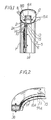
- FIG. 1 is a fragmentary sectional side view of the safety wheel of the present invention.
- FIG. 2 is a fragmentary plain side view of each of arc hollow members connected together to form the inner spare wheel of the safety wheel of the present invention.
- FIG. 3 is a plain side view of a circumference of the inner spare wheel being divided into three segments in advance then connected together to form one ring.
- FIG. 4 is a fragmentary sectional plain side view of an arc container storing a cooling liquid of the cooling device of the safety wheel of the present invention.
- FIG. 5 is a fragmentary sectional plain side view of a circular metal sheet which is used to make the plate member of the wheel rim of the safety wheel via a pressing machine.
- FIG. 6 is a fragmentary side view of an arc gasket having an arc groove on its circumference.
- FIG. 7 is an enlarged frangmentary side view of each of segments which are connected together to form the spare wheel of the present invention.
- FIG. 8 is an enlarged sectional plain side view of the arc container storing the cooling liquid of the cooling device of the safety wheel of the present invention.
- FIG. 9 is a sectional side view of a plug having a plastic cover which will be softened/melted automatically when the tire is flat.
- FIG. 10 is a fragmentary sectional side view of a wheel cover and a warning device of the present invention.
- the warning device is mounted on the wheel cover to provide a warning signal for the driver when the air in the tire is insufficient.
- the improved safety wheel of the present invention as shown in FIG. 1, comprises an assembled wheel rim 1A, an inner spare wheel, which is namely an inner subsidiary ring 8A fixed at the wheel rim 1A coaxially with the wheel rim 1A and located inside the tire 5A.
- the improved safety wheel of the present invention comprises several features will be described as belows:
- the warning device comprises at least one bell 160 ( FIG. 10 ) and a spring piece 161 beating the bell 160, which are mounted on a wheel cover 151 of a wheel.
- the spring piece 161 has only its first end 162 fixed on the wheel cover 151, its second end 163 being not fixed, and is toward an intake 149 which is designed on the wheel cover 151 so as to be pushed and to beat the bell 160 via a wind-force which is entering from the intake 149.
- the second end 163 of the spring piece 161 has a metallic ball-face 164 so as to increase the bell's sound when the spring piece 161 is beating the bell 160.
- the second end 161 is clamped by an U-shaped clamp 123 mounted on a valve which is controlled by the air pressure of the tire when the tire is of having deficient air attaining to some extent.
- One side symmetrical with the bell 160 and without being mounted on the bell of the wheel cover 151 is installed a balancer for balancing with the bell 160 so as to make the safety wheel balancing when turning.
- the prior art safety wheel has no warning device of the present invention so it can not warn the driver to replenish air to the tire and can not avoid using the spare wheel when the tire is losing air pressure but is not having a quick leakage.
Landscapes
- Engineering & Computer Science (AREA)
- Mechanical Engineering (AREA)
- Tires In General (AREA)
- Braking Arrangements (AREA)
- Air Bags (AREA)
Claims (10)
- Roue de sécurité comprenant une roue de secours intérieure qui est, proprement dit, une couronne auxiliaire intérieure, fixée au niveau de la jante de façon coaxiale à ladite jante et à l'intérieur du pneu, caractérisée en ce quechacun des éléments en arc (83), (84), (85), reliés ensemble pour former ladite roue de secours, est constitué d'une rigole en forme d'arc (8), ayant au moins trois côtés, l'ouverture de la rigole étant située au niveau de sa partie latérale, et avec laquelle un couvercle en forme d'arc (9) est combiné pour former un élément creux en forme d'arc (8A) ;lesdits éléments creux en forme d'arc (8A) ayant une bride (10) s'étendant à partir de leur partie en arc intérieure (10A) vers le centre de ladite jante, comprenant une pluralité d'ouvertures (11) pour permettre à une pluralité de boulons de s'étendre respectivement à travers et de relier chacun des éléments en arc entre l'élément formant plaque (1) et un élément annulaire (5) qui sont combinés ensemble pour former ladite jante (1A), fixant de ce fait ladite roue de secours de façon coaxiale à ladite jante (1A).
- Roue de sécurité selon la revendication 1, dans laquelle ledit couvercle en forme d'arc (9) comprend de plus une partie convexe auxiliaire (13) pour rentrer à l'intérieur de ladite ouverture de ladite rigole en forme d'arc (8) pour supporter les côtés en arc supérieur et inférieur de ladite ouverture de rigole par l'extrémité supérieure (9A) et l'extrémité inférieure (9B) dudit couvercle en forme d'arc (9) de façon à renforcer la force de support de ladite rigole en forme d'arc (8).
- Roue de sécurité selon la revendication 1, dans laquelle ladite rigole en forme d'arc (8) comprend de plus une pluralité de parties convexes auxiliaires (8B) sur le fond de la rigole pour renforcer sa force de support.
- Roue de sécurité selon la revendication 1, comprenant de plus des moyens de support (86) à l'intérieur dudit élément creux (8A) pour supporter les côtés en arc supérieur et inférieur de ladite rigole en forme d'arc (8), pour renforcer de ce fait la force de support de ladite rigole en forme d'arc (8).
- Roue de sécurité selon la revendication 1, dans laquelle une périphérie de l'élément qui est utilisé pour fabriquer l'élément formant plaque (1), qui est combiné à l'élément annulaire (5) pour former ladite jante (1A), possède une partie annulaire étagée (63) de façon à non seulement fabriquer aisément la bride (2) dudit élément formant plaque par l'intermédiaire d'une presse mais également à permettre de réduire le poids de ladite roue de sécurité.
- Roue de sécurité selon les revendications 1 à 5, comprenant de plus un dispositif de récupération (51) ou (52) pour récupérer et mettre en circulation le liquide de refroidissement qui est utilisé pour réduire la température intérieure dudit pneu quand ledit pneu est à plat et qui est évacué à partir d'un dispositif de refroidissement de ladite roue de sécurité, pour réduire de ce fait l'écoulement dudit liquide de refroidissement à l'extérieur dudit pneu quand ledit pneu est crevé.
- Roue de sécurité selon la revendication 6, comprenant de plus :un conteneur en forme d'arc stockant ledit liquide de refroidissement ;ledit conteneur en forme d'arc étant constitué d'une rigole en forme d'arc (41), d'un couvercle en forme d'arc (40) recouvrant ladite rigole en forme d'arc (41) et un joint d'étanchéité en forme de cadre semblable à un arc (91A) situé entre ladite rigole en forme d'arc (41) et ledit couvercle en forme d'arc (40), combinés pour former un conteneur en forme d'arc.
- Roue de sécurité selon les revendications 1 à 7, comprenant de plus un dispositif d'alerte avertissant le conducteur qu'il faut refaire le plein d'air du pneu et éviter d'utiliser ladite roue de secours.
- Roue de sécurité selon la revendication 1, comprenant de plus un joint d'étanchéité ayant une rainure en arc (79), ladite bride (10) étant insérée dans cette dernière et ensuite reliée entre ledit élément formant plaque (1) et ledit élément annulaire (5) suivant ladite bride, pour rendre ainsi étanche l'arc intérieur (79A) de ladite bride (10) par le fond de ladite rainure en arc (79) et pour empêcher l'air de s'échapper.
- Roue de sécurité selon la revendication 1, dans laquelle ladite bride (10) est située au niveau d'un côté particulier dudit arc intérieur de ladite rigole en forme d'arc (8) de façon à avoir ladite roue de secours située au niveau du centre de la chambre à air dudit pneu et à rendre ladite roue de secours plus équilibrée lors de la rotation.
Applications Claiming Priority (2)
| Application Number | Priority Date | Filing Date | Title |
|---|---|---|---|
| US86642692A | 1992-04-10 | 1992-04-10 | |
| US866426 | 1992-04-10 |
Publications (2)
| Publication Number | Publication Date |
|---|---|
| EP0569710A1 EP0569710A1 (fr) | 1993-11-18 |
| EP0569710B1 true EP0569710B1 (fr) | 1997-07-09 |
Family
ID=25347589
Family Applications (1)
| Application Number | Title | Priority Date | Filing Date |
|---|---|---|---|
| EP93105889A Expired - Lifetime EP0569710B1 (fr) | 1992-04-10 | 1993-04-08 | Roue de sécurité contenant une roue de secours à son intérieur |
Country Status (6)
| Country | Link |
|---|---|
| EP (1) | EP0569710B1 (fr) |
| CN (2) | CN1039296C (fr) |
| AT (1) | ATE155080T1 (fr) |
| AU (1) | AU3686493A (fr) |
| CA (1) | CA2093694A1 (fr) |
| DE (1) | DE69311969T2 (fr) |
Cited By (1)
| Publication number | Priority date | Publication date | Assignee | Title |
|---|---|---|---|---|
| WO2011096788A1 (fr) * | 2010-02-05 | 2011-08-11 | Dhayalan Asoka | Ensemble de pneu de secours à segments |
Families Citing this family (22)
| Publication number | Priority date | Publication date | Assignee | Title |
|---|---|---|---|---|
| WO1999006229A1 (fr) * | 1997-07-31 | 1999-02-11 | Lin Yng Lang | Moyeu pour l'installation de roue de secours et organe empechant a le pneumatique de se degonfler lorsque ladite roue est installee sur le moyeu |
| WO2002024475A1 (fr) * | 2000-09-21 | 2002-03-28 | Zhenglin Du | Pneu a securite renforcee ayant une protection contre l'eclatement |
| EP1412207B1 (fr) * | 2001-07-19 | 2008-04-16 | Société de Technologie Michelin | Insert de roulage a plat pour pneumatiques |
| AR033628A1 (es) | 2002-05-06 | 2003-12-26 | Jose Santiago Rolla | Llanta con soporte interior ranurado de emergencia y neumatico para dicha llanta |
| EP1550566B1 (fr) * | 2002-05-28 | 2008-06-25 | Topy Kogyo Kabushiki Kaisha | Appui de roulage a plat pour vehicle |
| FR2863203B1 (fr) * | 2003-12-08 | 2007-06-08 | Hutchinson | Dispositif de roulage a plat pour vehicule automobile et ensemble monte l'incorporant |
| US7575030B2 (en) | 2003-12-10 | 2009-08-18 | Hutchinson | Runflat device for a motor vehicle, and a mounted assembly incorporating it |
| US7347241B2 (en) | 2004-04-06 | 2008-03-25 | Gardetto William W | Run-flat support system for a pneumatic tired wheel and method for installing same |
| CN2721428Y (zh) * | 2004-08-10 | 2005-08-31 | 叶俊杰 | 汽车轮胎保险装置 |
| CN100355590C (zh) * | 2004-10-15 | 2007-12-19 | 戚永维 | 安全轮 |
| US20060289099A1 (en) | 2005-06-27 | 2006-12-28 | Steinke Richard A | Run flat tire insert system |
| US8281835B2 (en) | 2008-03-24 | 2012-10-09 | Dynamic Runflats, Inc. | Run-flat support assembly for a pneumatic tired wheel and method for use of same |
| US8196629B2 (en) | 2008-05-01 | 2012-06-12 | Dynamic Runflats, Inc. | Run-flat support system for a pneumatic tired wheel and method for installing same |
| CN102673321A (zh) * | 2012-05-30 | 2012-09-19 | 徐新琦 | 一种安全轮胎的矮胎冠三瓣式内支撑体 |
| CN103568697A (zh) * | 2013-11-05 | 2014-02-12 | 安徽工贸职业技术学院 | 一种安全型汽车轮胎 |
| DE102017115182A1 (de) * | 2017-07-06 | 2019-01-10 | Gv Engineering Gmbh | Notlaufrad mit Montageelement |
| CN110053429B (zh) * | 2018-01-19 | 2023-12-15 | 宇通客车股份有限公司 | 车轮及高压气舱、胎内充气系统 |
| CN108284713A (zh) * | 2018-02-22 | 2018-07-17 | 中信戴卡股份有限公司 | 一种轮毂轮胎系统自动恒压装置 |
| CN108583168B (zh) * | 2018-05-04 | 2023-04-21 | 南京工程学院 | 一种刚度可调的汽车安全轮胎弹性内支撑装置及其装配方法 |
| CN111391579B (zh) * | 2020-05-06 | 2025-06-24 | 贵州轮胎股份有限公司 | 一种防弹轮胎结构 |
| CN112606631A (zh) * | 2020-12-21 | 2021-04-06 | 孔德杰 | —种具有抗磨橡胶胎面的轮胎 |
| CN114030323B (zh) * | 2021-11-23 | 2023-12-15 | 北京迈克恒通科技有限公司 | 一种轮胎运行时爆胎用安全应急防护装置 |
Family Cites Families (8)
| Publication number | Priority date | Publication date | Assignee | Title |
|---|---|---|---|---|
| DE2004740C3 (de) * | 1970-02-03 | 1980-08-28 | Continental Gummi-Werke Ag, 3000 Hannover | Notlaufring fur luftbereifte Fahrzeugräder |
| US4077453A (en) * | 1970-06-20 | 1978-03-07 | Dunlop Holdings Limited | Tire and wheel assemblies |
| US4031940A (en) * | 1975-02-21 | 1977-06-28 | The B. F. Goodrich Company | Pneumatic tire |
| US4173243A (en) * | 1975-10-17 | 1979-11-06 | Dunlop Limited | Safety tire and wheel rim assembly |
| US4054168A (en) * | 1976-04-15 | 1977-10-18 | The Goodyear Tire & Rubber Company | Fluid dispensing apparatus for tire wheel assembly |
| US4212339A (en) * | 1979-01-02 | 1980-07-15 | The Goodyear Tire & Rubber Company | Tire/wheel assembly with low molecular weight coolant-lubricant |
| FR2579142B1 (fr) * | 1985-03-21 | 1988-04-15 | Broutin Robert | Pneumatique comprenant une structure interne rapportee a maintien en place ameliore |
| EP0490585A1 (fr) * | 1990-12-07 | 1992-06-17 | Yng-Lang Lin | Roue de sécurite pour véhicules avec une roue à l'intérieur du pneumatique |
-
1993
- 1993-04-08 AT AT93105889T patent/ATE155080T1/de active
- 1993-04-08 DE DE69311969T patent/DE69311969T2/de not_active Expired - Fee Related
- 1993-04-08 CA CA002093694A patent/CA2093694A1/fr not_active Abandoned
- 1993-04-08 CN CN93104026.4A patent/CN1039296C/zh not_active Expired - Fee Related
- 1993-04-08 AU AU36864/93A patent/AU3686493A/en not_active Abandoned
- 1993-04-08 EP EP93105889A patent/EP0569710B1/fr not_active Expired - Lifetime
- 1993-04-08 CN CN93209116.4U patent/CN2193824Y/zh not_active Expired - Fee Related
Cited By (1)
| Publication number | Priority date | Publication date | Assignee | Title |
|---|---|---|---|---|
| WO2011096788A1 (fr) * | 2010-02-05 | 2011-08-11 | Dhayalan Asoka | Ensemble de pneu de secours à segments |
Also Published As
| Publication number | Publication date |
|---|---|
| CA2093694A1 (fr) | 1993-10-11 |
| EP0569710A1 (fr) | 1993-11-18 |
| CN2193824Y (zh) | 1995-04-05 |
| CN1080240A (zh) | 1994-01-05 |
| DE69311969T2 (de) | 1998-02-05 |
| CN1039296C (zh) | 1998-07-29 |
| AU3686493A (en) | 1993-10-14 |
| ATE155080T1 (de) | 1997-07-15 |
| DE69311969D1 (de) | 1997-08-14 |
Similar Documents
| Publication | Publication Date | Title |
|---|---|---|
| EP0569710B1 (fr) | Roue de sécurité contenant une roue de secours à son intérieur | |
| US7204562B2 (en) | Wheel clad assembly | |
| EP0615865B1 (fr) | Dispositif d'étanchéité pour roues à rayons à bandages pneumatiques sans chambre à air | |
| US7469973B2 (en) | Fabricated vehicle wheel having a disc with a plurality of strengthening ribs | |
| US4770220A (en) | High strength three-piece wheel | |
| US4408647A (en) | Vehicle wheel | |
| CA1086617A (fr) | Pneu avec bandage interieur permettant de rouler en cas de crevaison | |
| US3786852A (en) | Tire changer apparatus | |
| US4549590A (en) | Resilient wheels | |
| US4212338A (en) | Vehicle wheel with annular emergency support | |
| BR0206231B1 (pt) | roda de veìculo fabricada de face inteira. | |
| US7475910B1 (en) | Container having internal bulkhead | |
| EP0130136B1 (fr) | Dispositif pour le roulement à plat destiné aux pneumatiques | |
| CN215792966U (zh) | 一种抗震效果好的高强度轮毂防脱圈 | |
| JPS5975801A (ja) | 特に自転車用の空気タイヤを有する車輪 | |
| US20030122415A1 (en) | Wheel for a motor vehicle | |
| US4153302A (en) | Motor vehicle safety wheel | |
| GB2108914A (en) | A disc wheel for pneumatic tyres | |
| US4782877A (en) | Vehicle wheel for pneumatic tire | |
| US20040035512A1 (en) | Tire/wheel assembly and pneumatic tire | |
| US2160272A (en) | Vehicle wheel | |
| HU192432B (en) | Vehicle wheel | |
| US5082040A (en) | Vehicle wheel for a pneumatic tire | |
| KR100288050B1 (ko) | 환형 테를 스프링과 댐퍼로 연결한 립 조립체 | |
| US2581736A (en) | Rim and tire assembly |
Legal Events
| Date | Code | Title | Description |
|---|---|---|---|
| PUAI | Public reference made under article 153(3) epc to a published international application that has entered the european phase |
Free format text: ORIGINAL CODE: 0009012 |
|
| AK | Designated contracting states |
Kind code of ref document: A1 Designated state(s): AT BE CH DE DK ES FR GB GR IE IT LI LU MC NL PT SE |
|
| RBV | Designated contracting states (corrected) |
Designated state(s): AT BE DE DK ES FR GB GR IT LU NL PT SE |
|
| 17P | Request for examination filed |
Effective date: 19940516 |
|
| 17Q | First examination report despatched |
Effective date: 19950405 |
|
| GRAG | Despatch of communication of intention to grant |
Free format text: ORIGINAL CODE: EPIDOS AGRA |
|
| GRAH | Despatch of communication of intention to grant a patent |
Free format text: ORIGINAL CODE: EPIDOS IGRA |
|
| GRAH | Despatch of communication of intention to grant a patent |
Free format text: ORIGINAL CODE: EPIDOS IGRA |
|
| GRAA | (expected) grant |
Free format text: ORIGINAL CODE: 0009210 |
|
| AK | Designated contracting states |
Kind code of ref document: B1 Designated state(s): AT BE DE DK ES FR GB GR IT LU NL PT SE |
|
| PG25 | Lapsed in a contracting state [announced via postgrant information from national office to epo] |
Ref country code: NL Free format text: LAPSE BECAUSE OF FAILURE TO SUBMIT A TRANSLATION OF THE DESCRIPTION OR TO PAY THE FEE WITHIN THE PRESCRIBED TIME-LIMIT Effective date: 19970709 Ref country code: GR Free format text: LAPSE BECAUSE OF FAILURE TO SUBMIT A TRANSLATION OF THE DESCRIPTION OR TO PAY THE FEE WITHIN THE PRESCRIBED TIME-LIMIT Effective date: 19970709 Ref country code: ES Free format text: THE PATENT HAS BEEN ANNULLED BY A DECISION OF A NATIONAL AUTHORITY Effective date: 19970709 Ref country code: DK Effective date: 19970709 |
|
| REF | Corresponds to: |
Ref document number: 155080 Country of ref document: AT Date of ref document: 19970715 Kind code of ref document: T |
|
| REF | Corresponds to: |
Ref document number: 69311969 Country of ref document: DE Date of ref document: 19970814 |
|
| ITF | It: translation for a ep patent filed | ||
| PG25 | Lapsed in a contracting state [announced via postgrant information from national office to epo] |
Ref country code: SE Effective date: 19971009 |
|
| PG25 | Lapsed in a contracting state [announced via postgrant information from national office to epo] |
Ref country code: PT Effective date: 19971017 |
|
| ET | Fr: translation filed | ||
| NLV1 | Nl: lapsed or annulled due to failure to fulfill the requirements of art. 29p and 29m of the patents act | ||
| PG25 | Lapsed in a contracting state [announced via postgrant information from national office to epo] |
Ref country code: LU Free format text: LAPSE BECAUSE OF NON-PAYMENT OF DUE FEES Effective date: 19980408 |
|
| PLBE | No opposition filed within time limit |
Free format text: ORIGINAL CODE: 0009261 |
|
| 26N | No opposition filed | ||
| PGFP | Annual fee paid to national office [announced via postgrant information from national office to epo] |
Ref country code: FR Payment date: 20010430 Year of fee payment: 9 Ref country code: AT Payment date: 20010430 Year of fee payment: 9 |
|
| PGFP | Annual fee paid to national office [announced via postgrant information from national office to epo] |
Ref country code: BE Payment date: 20010731 Year of fee payment: 9 |
|
| REG | Reference to a national code |
Ref country code: GB Ref legal event code: IF02 |
|
| PG25 | Lapsed in a contracting state [announced via postgrant information from national office to epo] |
Ref country code: AT Free format text: LAPSE BECAUSE OF NON-PAYMENT OF DUE FEES Effective date: 20020408 |
|
| PG25 | Lapsed in a contracting state [announced via postgrant information from national office to epo] |
Ref country code: BE Free format text: LAPSE BECAUSE OF NON-PAYMENT OF DUE FEES Effective date: 20020430 |
|
| PGFP | Annual fee paid to national office [announced via postgrant information from national office to epo] |
Ref country code: GB Payment date: 20021007 Year of fee payment: 10 |
|
| PGFP | Annual fee paid to national office [announced via postgrant information from national office to epo] |
Ref country code: DE Payment date: 20021009 Year of fee payment: 10 |
|
| PG25 | Lapsed in a contracting state [announced via postgrant information from national office to epo] |
Ref country code: FR Free format text: LAPSE BECAUSE OF NON-PAYMENT OF DUE FEES Effective date: 20021231 |
|
| REG | Reference to a national code |
Ref country code: FR Ref legal event code: ST |
|
| PG25 | Lapsed in a contracting state [announced via postgrant information from national office to epo] |
Ref country code: GB Free format text: LAPSE BECAUSE OF NON-PAYMENT OF DUE FEES Effective date: 20030408 |
|
| PG25 | Lapsed in a contracting state [announced via postgrant information from national office to epo] |
Ref country code: DE Free format text: LAPSE BECAUSE OF NON-PAYMENT OF DUE FEES Effective date: 20031101 |
|
| GBPC | Gb: european patent ceased through non-payment of renewal fee |
Effective date: 20030408 |
|
| PG25 | Lapsed in a contracting state [announced via postgrant information from national office to epo] |
Ref country code: IT Free format text: LAPSE BECAUSE OF NON-PAYMENT OF DUE FEES Effective date: 20050408 |