EP0569829A1 - Chaussure de ski - Google Patents
Chaussure de ski Download PDFInfo
- Publication number
- EP0569829A1 EP0569829A1 EP93107247A EP93107247A EP0569829A1 EP 0569829 A1 EP0569829 A1 EP 0569829A1 EP 93107247 A EP93107247 A EP 93107247A EP 93107247 A EP93107247 A EP 93107247A EP 0569829 A1 EP0569829 A1 EP 0569829A1
- Authority
- EP
- European Patent Office
- Prior art keywords
- tongue
- shell
- joint part
- ski boot
- joint
- Prior art date
- Legal status (The legal status is an assumption and is not a legal conclusion. Google has not performed a legal analysis and makes no representation as to the accuracy of the status listed.)
- Withdrawn
Links
Images

Classifications
-
- A—HUMAN NECESSITIES
- A43—FOOTWEAR
- A43B—CHARACTERISTIC FEATURES OF FOOTWEAR; PARTS OF FOOTWEAR
- A43B5/00—Footwear for sporting purposes
- A43B5/04—Ski or like boots
- A43B5/0415—Accessories
-
- A—HUMAN NECESSITIES
- A43—FOOTWEAR
- A43B—CHARACTERISTIC FEATURES OF FOOTWEAR; PARTS OF FOOTWEAR
- A43B5/00—Footwear for sporting purposes
- A43B5/04—Ski or like boots
- A43B5/0427—Ski or like boots characterised by type or construction details
- A43B5/0435—Adjustment of the boot to the foot
Definitions
- the invention relates to a ski boot mentioned in the preamble of claim 1.
- the ski boot which is designed as a "beginner” and can be closed with the usual tension buckles, has a shell that surrounds the sole. This shell also forms a cap that covers at least the toe area and a front shaft part that adjoins the cap part and that laterally covers the instep area and the lower leg area.
- the front part of the shaft has an elongated opening at the top, which extends from the rear edge of the cap along the foot, the instep and the front of the shin to the edge of the shoe. The opening has a certain width to allow entry into the ski boot.
- a tongue is used, which is fastened by a connecting device to the rear edge of the cap so that when the shoe is open, ie when the tensioning and closing device is released, it is pivoted toward the toe region by about 45 ° into an entry position can, at the same time a displacement transversely to the pivot axis or backwards and upwards away from the cap, so that a certain adaptation to the foot or leg can take place in the longitudinal direction of the shoe.
- the pivot pins which form the axis for the pivoting movement of the tongue, are slidably received in elongate recesses by lateral guide plates.
- This type of tongue attachment in the known ski boot has various disadvantages.
- the tongue attachment is not easy to assemble; Above all, the fixing of the pivot pins in the recesses in the side tabs is difficult, since it requires a riveting process on the practically finished ski boot.
- a tongue fastened in this way can only be swiveled by about 45 °, which is not enough for a comfortable entry.
- the length adjustment is only possible to a very limited extent when the ski boot is closed, since when the tensioning and closing device is tensioned, the tongue and thus, of course, the pivot pin are pressed down, which means that the pivot pin is only very limited let it move.
- the present invention is therefore based on the object of providing a ski boot of the type mentioned at the outset, in which the tongue can be easily installed and which is very easy to carry and use.
- the connecting device by means of which the tongue is fastened to the shell, is arranged in the upper center and is designed such that, in contrast to the known ski boot, the relative pivoting movement and the relative displacement can take place independently of one another.
- the connecting device is designed as a two-part axle joint, one of which Joint part is firmly connected to the shell or the cap.
- the other joint part is connected to the tongue or to the shell by means of almost rigid connecting members in such a way that a relative movement can take place transversely to the axis of the joint and thus essentially in the longitudinal direction of the shoe, which is also possible when the tensioning and closing device acts and the Tongue is blocked from pivoting because the connecting elements are hardly compressed as a result.
- the desired length adjustment can also take place with the shoe closed.
- connection of the tongue or the shell with the corresponding joint part is advantageously carried out by means of a groove / wedge connection and a latching device. It is possible to provide a groove which is approximately U-shaped in plan view on the joint part and a corresponding wedge on the tongue or on the shell. It is of course also possible to arrange the groove on the tongue or on the shell and the wedge on the joint part.
- the U-shaped design of the groove / wedge connection largely prevents lateral displacement of the tongue.
- the fixed connection of the shell or the tongue with the corresponding joint part can take place by means of a snap or snap connection or by means of small bolts which are arranged integrally on the joint part and which protrude through recesses in the shell or the tongue and by means of fastening elements such as, for. B. resilient toothed lock washers are secured.
- the tongue can be designed to be interchangeable, so that new or different tongues can be fitted if the tongue shows signs of wear or if the needs of the user change.
- tongues with different thicknesses come into question, by which an adaptation to the foot is made possible, but in particular tongues with different elasticity, so that an adaptation to the different posture z. B. can be made in slalom or downhill.
- the connecting device is designed such that the connection of the tongue or the shell with the corresponding joint part, which permits the relative displacement, is secured by means of a releasable latching device.
- the distance along which the tongue or the shell on the one hand and the corresponding joint part on the other hand can be displaced relative to one another is preferably limited by providing a latching surface and a counter surface which, when the tongue or the shell is displaced from one another to the greatest extent come to the plant. This not only prevents one for the user. U. dangerously large displacement between tongue and shell and thereby a change in the state of tension, but also the penetration of snow into the groove / wedge connection partially loosened in such a configuration.
- integral pivots on one and corresponding bearing devices on the other joint part can be provided to reduce the number of components required.
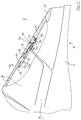
- the ski boot 2 has a shell 4 made of a relatively rigid material with an integrated sole 6, a cap 8 intended to cover the toe region and a cap which connects to the cap 8 backwards and covers the lateral and front instep - and leg area determined front shaft part 10.
- the ski boot 2 also includes a conventional rear shaft part (not shown) and a conventional tensioning and closing device (not shown) for tightly closing the ski boot 2.
- the shell 4 and the front shaft part 10 have an elongated opening 12 on the upper side, which extends from the rear Edge of the cap 8 extends over the central instep and rail area to the edge of the ski boot (not shown) and allows entry into the ski boot 2.
- a tongue 14 is used, which is attached to the rear edge of the cap 8 and, at least in its longitudinal direction, is more flexible than the shell 4.
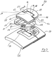
- a connecting device 30 with a two-part axle joint as can be seen in FIG. 3, for example, which is practically incompressible by the tensioning and closing device, is provided.
- a first joint part 32 of the connecting device 30 is fastened to a part 33 which is either rigidly fastened to the shell 4 according to FIG. 3 or is itself a part of the shell 4 according to FIGS. 1 and 2.
- the second joint part 34 of the connecting device 30 is fastened to a part 35 which is either rigidly fastened to the tongue 14 according to FIG. 3 or is itself part of the tongue 14 according to FIGS. 1 and 2.
- the connecting device 30 is slightly arched transversely to the longitudinal axis of the ski shoe in adaptation to the shape of the foot and shell, and its first joint part 32 has a curved end face 40 on the central part 36 in order to create space for the front upper edge 42 of the second joint part 34 when it is pivoted in the direction of arrow A relative to the first joint part 32 (FIG. 2).
- the first joint part 32 of the connecting device 30 is formed in an arc shape in plan view on its front side 44 and is provided with a recess 48 on its rear side 46.
- the parts 50 projecting to the rear of the recess 48 have, on their lower and not visible in FIGS. 1-3 and inner surfaces, horizontal and transverse to the longitudinal axis of the ski shoe, open towards the center, which - as will be described later - corresponding Take up the pivot of the second joint part 34.
- the second joint part 34 of the connecting device 30 has on its front surface a projection 58 which fits into the recess 48 of the first joint part 32.
- a pivot which is directed horizontally and transversely to the longitudinal axis of the ski shoe and projects outward is integrally formed and is received in one of the recesses of the first joint part 32 described above.
- the two pivots define an axis 60 about which the second joint part 34 can rotate relative to the first joint part 32.
- the side surfaces 62 and the rear surface 64 of the second joint part 34 have a circumferential, U-shaped groove 66.
- an arcuate closed hook 68 with a central opening 69 is formed on the second joint part 34.
- the upper surface of the part of this hook 68 which adjoins the opening 69 at the rear is designed as an inclined surface 70.
- a further inclined surface 72 is formed on the central area of the lower surface of the front joint part 34 (FIG. 1).
- the dimensions of the hook 68 are selected taking into account the material properties so that it can be elastically deformed in the longitudinal direction.
- the front part of the part 35 (FIG. 3) or the tongue 14 (FIGS. 1 and 2) has a U-shaped projection 74 which fits like a wedge into the groove 66 of the second joint part 34.
- the lower surface of the part 35 or the tongue 14 adjoining the projection 74 at the rear is designed as an oblique surface 76.
- the mode of operation of the parts of the ski boot 2 or the connecting device 30 described so far is as follows: When the ski boot is closed according to FIG. 1, the surfaces of the two joint parts 32 and 34 are arranged essentially in alignment without mutual inclination. The projection 74 of the tongue 14 is received in the groove 66 of the second joint part 34.
- the tongue 14 With a bending movement, e.g. B. due to a forward inclination of the shin, or in adaptation to the leg or sock volume, the tongue 14 slants backwards upwards, the projection 74 in the groove 66 starting to shift. Tilting is effectively prevented by the U-shaped design of the groove / wedge connection 66, 74.
- the distance B, by which the tongue 14 can move at most, is limited by the fact that a locking lug 78, on the underside of which the oblique surface 76 is formed, comes to rest against the edge of the opening 69 of the hook 68 acting as a counter surface, such as it is shown in Fig. 2.
- the dimensions of the various parts are selected such that the foremost part of the projection 74 is still in the groove 68 when the tongue 14 is in its rearmost or uppermost position. This prevents a complete loosening of the groove / key connection 68, 74.
- the tongue 14 From the closed position shown in FIG. 1 about the axis 60 in the direction of arrow A to the front in FIG. 2 Open or boarding position. Getting in and out is facilitated in that the tongue 14 is pivoted about 90 ° can be, in contrast to known ski boots of the same type, in which the tongue can only be pivoted by about 45 °.
- the pivoting movement of the tongue 14 is independent of the translatory movement of the tongue 14 described above, and it does not matter for the pivoting in what position the tongue 14 is relative to the second joint part 34.
- the tongue 14 can be easily dismantled when the ski boot 2 is open by slightly bending the elastic hook 68 in the direction of the arrow C (FIG. 2) and at the same time pulling the tongue 14 backwards or upwards. It is just as easy to mount the tongue 14. It is not necessary to bend the hook 68 away. This happens automatically by sliding the inclined surfaces 7o and 76 on each other.
- the connecting device can also be designed differently than was described with reference to FIGS. 1-3.
- a latching connection for the fixed connection between the first joint part 32 and the shell 4. This makes it easier to replace the connection device in the event of a defect.
- This additional latching connection can be designed in such a way that it allows a translational relative movement between the connected parts, as is the case with the described connection of the tongue with the second joint part, which practically results in a doubling of the length adjustment compared to the described ski boot. But it can also be a snap connection without the possibility of displacement, so that the wearing comfort is the same as that of the ski boot described above.
- a ski boot 2 which is easy to put on and take off Climbing out enables a considerable length adjustment even in the closed state and gives the possibility to easily remove the tongue or to replace it with another tongue without any aids.
Landscapes
- Health & Medical Sciences (AREA)
- General Health & Medical Sciences (AREA)
- Physical Education & Sports Medicine (AREA)
- Footwear And Its Accessory, Manufacturing Method And Apparatuses (AREA)
Applications Claiming Priority (2)
| Application Number | Priority Date | Filing Date | Title |
|---|---|---|---|
| CH1550/92 | 1992-05-14 | ||
| CH155092 | 1992-05-14 |
Publications (1)
| Publication Number | Publication Date |
|---|---|
| EP0569829A1 true EP0569829A1 (fr) | 1993-11-18 |
Family
ID=4213036
Family Applications (1)
| Application Number | Title | Priority Date | Filing Date |
|---|---|---|---|
| EP93107247A Withdrawn EP0569829A1 (fr) | 1992-05-14 | 1993-05-05 | Chaussure de ski |
Country Status (2)
| Country | Link |
|---|---|
| EP (1) | EP0569829A1 (fr) |
| JP (1) | JPH0630802A (fr) |
Cited By (3)
| Publication number | Priority date | Publication date | Assignee | Title |
|---|---|---|---|---|
| EP0657114A1 (fr) * | 1993-12-07 | 1995-06-14 | TECNICA S.p.A | Chaussure de ski avec rembourrage amélioré et languette glissante |
| US5647146A (en) * | 1994-08-04 | 1997-07-15 | Tecnica Spa | Tongue for internal shoes of ski boots |
| US6237253B1 (en) * | 1997-05-23 | 2001-05-29 | “Lowa” Sportschue GmbH | Shoe, optionally shoe with a high upper |
Citations (3)
| Publication number | Priority date | Publication date | Assignee | Title |
|---|---|---|---|---|
| FR1587712A (fr) * | 1968-08-27 | 1970-03-27 | ||
| DE1816811A1 (de) * | 1968-12-24 | 1970-06-25 | Josef Lederer | Skistiefel |
| DE2031751A1 (de) * | 1969-12-24 | 1972-01-27 | Secondo, Sergio, Turin (Italien) | Skischuh, aus einer steifen Schale gebildet, mit oberer Öffnung |
Family Cites Families (1)
| Publication number | Priority date | Publication date | Assignee | Title |
|---|---|---|---|---|
| DE3325663C2 (de) * | 1983-07-15 | 1985-08-22 | MTU Motoren- und Turbinen-Union München GmbH, 8000 München | Axial durchströmtes Schaufelgitter einer mit Gas oder Dampf betriebenen Turbine |
-
1993
- 1993-05-05 EP EP93107247A patent/EP0569829A1/fr not_active Withdrawn
- 1993-05-12 JP JP11064493A patent/JPH0630802A/ja active Pending
Patent Citations (3)
| Publication number | Priority date | Publication date | Assignee | Title |
|---|---|---|---|---|
| FR1587712A (fr) * | 1968-08-27 | 1970-03-27 | ||
| DE1816811A1 (de) * | 1968-12-24 | 1970-06-25 | Josef Lederer | Skistiefel |
| DE2031751A1 (de) * | 1969-12-24 | 1972-01-27 | Secondo, Sergio, Turin (Italien) | Skischuh, aus einer steifen Schale gebildet, mit oberer Öffnung |
Cited By (4)
| Publication number | Priority date | Publication date | Assignee | Title |
|---|---|---|---|---|
| EP0657114A1 (fr) * | 1993-12-07 | 1995-06-14 | TECNICA S.p.A | Chaussure de ski avec rembourrage amélioré et languette glissante |
| US5553402A (en) * | 1993-12-07 | 1996-09-10 | Tecnica Spa | Ski-boot with improved padding and slidable tongue |
| US5647146A (en) * | 1994-08-04 | 1997-07-15 | Tecnica Spa | Tongue for internal shoes of ski boots |
| US6237253B1 (en) * | 1997-05-23 | 2001-05-29 | “Lowa” Sportschue GmbH | Shoe, optionally shoe with a high upper |
Also Published As
| Publication number | Publication date |
|---|---|
| JPH0630802A (ja) | 1994-02-08 |
Similar Documents
| Publication | Publication Date | Title |
|---|---|---|
| AT411017B (de) | Snowboard - einstiegsbindung | |
| DE3878961T2 (de) | Schischuh. | |
| EP0265459B1 (fr) | Fixation de ski de fond | |
| AT389632B (de) | Skischuh | |
| DE69704650T2 (de) | Sportschuh mit beweglichem Oberteil | |
| AT401710B (de) | Skischuh | |
| DE3442780A1 (de) | Alpiner skischuh | |
| DE1947575A1 (de) | Skistiefel | |
| DE3518233A1 (de) | Schi-schuh | |
| CH691663A5 (de) | Bindung für Sportgeräte. | |
| DE2244695C3 (de) | Skistiefel | |
| DE69822722T2 (de) | Sportschuh mit bestimmter Biegsamkeit | |
| DE69504518T2 (de) | Bindung für einen schuh auf einem snowboard | |
| DE69312682T2 (de) | Langlaufschischuh und kombination von schi, bindung und schuh | |
| DE69703760T2 (de) | Schuh, insbesondere für Schlittschuhläufer | |
| EP0707505B1 (fr) | Dispositif de reglage en longueur | |
| DE3876554T2 (de) | Schischuh mit fersenhalterung. | |
| EP0016750A1 (fr) | Chaussure de ski de fond et ski de fond | |
| EP0581802B1 (fr) | Chaussure de sport | |
| EP0575466B1 (fr) | Chaussure de ski | |
| DE69124018T2 (de) | Hintere einstellbare Stützvorrichtung, insbesondere für Skischuhe | |
| DE3844038A1 (de) | Vorrichtung zum einstellen der relativlage zweier teile und verwendung derselben bei einem ski-schuh | |
| AT401216B (de) | Skischuh | |
| EP0569829A1 (fr) | Chaussure de ski | |
| EP0441776B1 (fr) | Chaussure monocoque de ski a tige composite |
Legal Events
| Date | Code | Title | Description |
|---|---|---|---|
| PUAI | Public reference made under article 153(3) epc to a published international application that has entered the european phase |
Free format text: ORIGINAL CODE: 0009012 |
|
| 17P | Request for examination filed |
Effective date: 19930720 |
|
| AK | Designated contracting states |
Kind code of ref document: A1 Designated state(s): AT CH DE FR IT LI |
|
| 17Q | First examination report despatched |
Effective date: 19940112 |
|
| 18D | Application deemed to be withdrawn |
Effective date: 19940525 |