EP0569887B1 - Dispositif pour assembler et brocher des produits imprimés pliés - Google Patents
Dispositif pour assembler et brocher des produits imprimés pliés Download PDFInfo
- Publication number
- EP0569887B1 EP0569887B1 EP93107489A EP93107489A EP0569887B1 EP 0569887 B1 EP0569887 B1 EP 0569887B1 EP 93107489 A EP93107489 A EP 93107489A EP 93107489 A EP93107489 A EP 93107489A EP 0569887 B1 EP0569887 B1 EP 0569887B1
- Authority
- EP
- European Patent Office
- Prior art keywords
- supports
- heads
- stapling
- wire length
- printed sheets
- Prior art date
- Legal status (The legal status is an assumption and is not a legal conclusion. Google has not performed a legal analysis and makes no representation as to the accuracy of the status listed.)
- Expired - Lifetime
Links
Images







Classifications
-
- B—PERFORMING OPERATIONS; TRANSPORTING
- B42—BOOKBINDING; ALBUMS; FILES; SPECIAL PRINTED MATTER
- B42B—PERMANENTLY ATTACHING TOGETHER SHEETS, QUIRES OR SIGNATURES OR PERMANENTLY ATTACHING OBJECTS THERETO
- B42B4/00—Permanently attaching together sheets, quires or signatures by discontinuous stitching with filamentary material, e.g. wire
- B42B4/02—Rotary type stitching machines
-
- B—PERFORMING OPERATIONS; TRANSPORTING
- B42—BOOKBINDING; ALBUMS; FILES; SPECIAL PRINTED MATTER
- B42C—BOOKBINDING
- B42C1/00—Collating or gathering sheets combined with processes for permanently attaching together sheets or signatures or for interposing inserts
- B42C1/12—Machines for both collating or gathering and permanently attaching together the sheets or signatures
-
- B—PERFORMING OPERATIONS; TRANSPORTING
- B65—CONVEYING; PACKING; STORING; HANDLING THIN OR FILAMENTARY MATERIAL
- B65H—HANDLING THIN OR FILAMENTARY MATERIAL, e.g. SHEETS, WEBS, CABLES
- B65H5/00—Feeding articles separated from piles; Feeding articles to machines
- B65H5/32—Saddle-like members over which partially-unfolded sheets or signatures are fed to signature-gathering, stitching, or like machines
-
- B—PERFORMING OPERATIONS; TRANSPORTING
- B65—CONVEYING; PACKING; STORING; HANDLING THIN OR FILAMENTARY MATERIAL
- B65H—HANDLING THIN OR FILAMENTARY MATERIAL, e.g. SHEETS, WEBS, CABLES
- B65H2301/00—Handling processes for sheets or webs
- B65H2301/40—Type of handling process
- B65H2301/43—Gathering; Associating; Assembling
- B65H2301/436—Gathering; Associating; Assembling on saddles
- B65H2301/4361—Gathering; Associating; Assembling on saddles on a rotary carrier rotating around an axis parallel to the saddles
-
- B—PERFORMING OPERATIONS; TRANSPORTING
- B65—CONVEYING; PACKING; STORING; HANDLING THIN OR FILAMENTARY MATERIAL
- B65H—HANDLING THIN OR FILAMENTARY MATERIAL, e.g. SHEETS, WEBS, CABLES
- B65H2301/00—Handling processes for sheets or webs
- B65H2301/40—Type of handling process
- B65H2301/44—Moving, forwarding, guiding material
- B65H2301/447—Moving, forwarding, guiding material transferring material between transport devices
- B65H2301/44795—Saddle conveyor with saddle member extending transversally to transport direction
Definitions
- the present invention relates to a device for collecting folded printed sheets, according to the preamble of claim 1.
- Such a device is known for example from DE-OS 36 16 566 or the corresponding US Pat. No. 4,735,406.
- This has a collecting drum with saddle-shaped supports arranged parallel to a common axis of rotation and driven around it. In the direction of the axis of rotation, two feeders are successively provided for depositing folded printed sheets on the supports and subsequently a stitching station for stitching the printed sheets lying one above the other.
- the collected and stapled printed sheets are placed on a conveyor belt for stapling immediately after stapling.
- the stapling station has a plurality of pairs of stapling heads which are arranged at a distance from the parallel supports on a bracket which is pivotably mounted on the axis of rotation of the drum.
- the bracket is moved back and forth by means of a swivel drive, the stitching heads simultaneously placing one clamp each in the printed sheets placed on the supports during the synchronization with the supports.
- a wire is fed to each of these known stitching heads, each of which wire by means of a cutting device arranged on the stitching head a wire section is cut off.
- This wire section is bent by means of a slidably mounted stamp around a die to form a clamp, which is pressed out of the stamp by means of a likewise slidably mounted plunger and inserted into the printed sheets.
- a disadvantage of this known device is that the stapling station must have a complex drive which has to exert large acceleration forces, in particular at high processing speeds.
- the movement of the stitching heads must be precisely synchronized with the supports during each working cycle of the stitching station.
- a wire is to be fed to each stitching head, which is complex for moving the stitching heads, both for feeding the wire and for the stitching heads themselves.
- EP-A-0 205 144 or the corresponding US Pat. No. 4,750,661 describes a stapling station for stapling printed sheets carried by a rotating cylinder.
- a cross-shaped holding device which is driven to rotate against a direction of rotation of the cylinder about a shaft parallel to the axis of the cylinder, three stitching heads are arranged side by side, which run past three drawer section dispensers common to all corresponding stitching heads.
- the circular movement path of the stitching heads touches the surface of the cylinder and the rotary movement of the holding device is synchronized with the cylinder in such a way that the printed sheets to be stitched together always meet stitching heads.
- the cylinder and the Drant section dispenser are located on the outside of the movement spell of the stitching heads.
- a device for collecting folded printed sheets from CH-PS 645 074 and the corresponding US-PS 4,408,755 is also known.
- This facility also points a drum with supports running parallel to a common axis of rotation.
- the folded printed sheets are connected to each other and placed on top of each other to form zigzag bands.
- staples are placed in the tapes supported one above the other by the supports.
- the stitching heads which are arranged essentially one behind the other at a distance from the supports, run along a closed movement path at a substantially the same speed as the supports.
- the closed movement path of the stitching heads leads past a wire section dispenser common to the stitching heads.
- a single wire section dispenser thus supplies all of the stitching heads of a stitching head arrangement, which keeps the necessary facilities for the provision of wire sections extremely small and, moreover, enables the stitching heads to be constructed simply, since the stitching heads themselves no longer have to have a cutting device.
- the takeover of the wire sections by the stapling heads on the side of the movement ban of the stapling heads facing away from the orbit of the supports allows the staples to be processed in a position different from the stapling position. This allows practically any shape of the movement path and the arrangement of the wire section dispenser even where the movement path runs along the orbit.
- the distance between the stitching heads along the path of movement is so great that when the staples are set, the distance between the staples corresponds to the distance between the supports.
- the mutual spacing of the stitching heads can thus be slightly different with respect to the spacing of the supports.
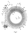
- FIG. 1 shows a collecting drum 10, as described in EP-A-0 341 425 or the corresponding US patent No. 5,052,667.
- This collecting drum 10 has saddle-shaped supports 14 arranged around a common axis of rotation 12, running in the direction of the axis of rotation 12 and driven in the direction of rotation U.
- a carriage 16 which can be moved back and forth in the direction of the rotational axis 12 is provided with a controllable clamping arrangement 18 for the folded printed sheets 20 straddling the supports 14.
- a stapling station 22 has a stapling head arrangement 24 with stapling heads 28 arranged one behind the other along a movement path 26 coaxially around the collecting drum 10.
- a stapling head 28 is assigned to each support 14, which are thus arranged essentially at the same mutual distance A as the supports 14.
- a wire section dispenser designated 30, is provided, along which the movement path 26 passes.
- This wire section dispenser 30 has a cutting device 32, by means of which wire sections 38 are separated from a wire 36 drawn off from a supply roll 34. Downstream of the cutting device 32 is a magazine 40 fed by the cutting device 32 with wire sections 38.
- the device shown in Fig. 1 operates as follows. Seen in the conveying direction of the carriage 16, the Stapling station 22 upstream feed stations for printed sheets in a known manner. These feed stations each place a folded printed sheet 20 astride each support 14 passing in the direction of rotation U at the feed station. Before in each case a support 14 runs into the lower region of its circular path of movement, the relevant clamping arrangement 18 is clamped in order to hold the parts of the printed sheets 20 reaching into the corresponding carriage 16. In the course of passing through the lower half of the path of movement of the supports 14, the carriages 16 make a working stroke in the longitudinal direction of the rotational axis 12 to the next feed station or to the stapling station 22.
- the stitching heads 28 are also driven in the direction of rotation U in synchronism with the supports 14.
- a stapling head 28 runs past the feed wheel 42, it takes over a wire section 38 from the feed wheel 42.
- the wire section 38 now held by the stapling head 28 is formed into a clamp, as is the case here will be described in detail below.
- the clip is moved from the side of the stitching heads 28 lying on the outside in the radial direction onto the inside of the supports 14 brought to the side.
- the stapling heads 28 concerned are placed on the printing sheets 20 placed one on top of the other on the supports 14 lowered and the clamps inserted into the printed sheets.
- the distance A of the stapling heads 28 corresponds to the spacing of the supports 14. After the staples have been placed, the stapling heads 28 are raised again, after which the collected and stapled printed sheets 20 are fed to a removal station in the course of the next rotation of the collecting drum 10 in the direction of the rotational axis 12 become.
- the collecting drum 10 shown in FIGS. 2 and 3 corresponds to that of FIG. 1 and is therefore no longer described in detail.
- the movement path 26 for the stitching heads 28 is kidney-shaped and runs in an area D along the orbit of the supports 14 of the collecting drum 10.
- the collecting drum 10 is arranged outside the movement path 26 and the wire section dispenser 30, which is only indicated schematically, within it.
- the collecting drum 10 rotates counterclockwise U and the stitching heads 28 are driven in the opposite direction U 'at the same speed as that of the pads 14.
- the distance A of the stapling heads 28 corresponds to the spacing of the supports 14 when the staples are set, so that in area D for setting the staples a corresponding stapling head 28 runs with each support.
- FIG. 3 essentially corresponds to that of FIG. 2.
- the movement path 26 is circular and thus the area D is essentially shortened to a point D '.
- the respective stapling head 28 comes into contact only very briefly with the staple in the printed sheets 20 deposited on the supports 14.
- the stitching heads 28 are arranged along their movement path 26 at a distance A, which corresponds to the distance between the supports 14 of the collecting drum 10 when the clamps are set.
- the embodiment of the device for collecting folded printed sheets 20 shown in FIG. 4 has a collecting conveyor 46 as described in EP-A-0 346 578 or in the corresponding US Pat. No. 5,104,108 or with a similar structure in the EP -B-0 095 603 or the corresponding US-A-4,489,930.
- This has a pulling element 50 which is guided around two spaced apart, only indicated by its essentially horizontal axes of rotation 48, deflection wheels, on which supports 14 are arranged at certain intervals one behind the other, parallel to one another and at right angles to the direction of rotation U.
- the stapling station 22 has a stapling head arrangement 24 arranged above the collecting conveyor 46 with an elongated movement path 26 for the stapling heads 28.
- the stitching heads 28 are arranged on a pulling element, not shown, with the same spacing A as the supports 14 in the area D.
- the traction element is driven in the direction U 'at the same speed as the traction element 50 in the direction U.
- the stitching heads 28 thus run in the area D in synchronism with the supports 14 and move past the wire section dispenser 30 remote from the area D.
- the stapling station 22 is connected upstream of the stapling station 22 along the upper run of the collecting conveyor 46, feed stations for placing folded printed sheets 20 on the supports 14. Of course, the stapling station 22 is followed by an exit station for the stapled printed sheets 20.
- the stapling stations 22 shown in FIGS. 2 to 4 function as follows. Each stitching head 28 takes over a wire section from the wire section dispenser 30 as it passes by. In the course of the circular movement in the direction of the arrow U 'along the movement path 26, a clip is bent from the wire section in the area between the wire section dispenser 30 and the area D, D' (staple setting area) and this is placed on the side of the stitching heads 28 which is outside the movement path 26 . In the area D, D ', the stitching heads 28 come to rest on the relevant supports 14 or the printed sheets 20 placed thereon and place the clamp in the printed sheets 20.
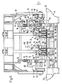
- the stapling station 22 shown in FIGS. 5 and 6 has two stapling head arrangements 24 arranged on the same holding arrangement 52.
- the holding arrangement 52 is annular and encompasses coaxially the collecting drum 10 which is driven about the axis of rotation 12 in the direction of rotation U.
- the holding arrangement 52 has two retaining rings 54 which are spaced apart from one another in the direction of the axis of rotation 12 and which are connected to one another in a cage-like manner by means of grating bars 56.
- the retaining rings 54 are each freely rotatably mounted on three bearing rollers 60 which are arranged on a frame 58 and are approximately equally spaced from one another.
- Each support 14 is assigned a stitching head 28 from each stitching head arrangement 24, which are fastened to a common support profile 62 at a distance from one another in the direction of the axis of rotation 12 (FIG. 6).
- a C-shaped bearing part 64 is fastened to the support profile 62 at both ends, and its free end regions 64 ′ are each guided on a bearing shaft 66 so as to be displaceable in the radial direction E.
- the bearing shaft 66 is arranged on a likewise C-shaped holding part 68 fastened to the respective holding ring 54, the end region 64 ′ of the bearing part 64 shown above in FIG. 6 being encompassed by the holding part 68.
- a compression spring 70 is guided around the bearing shaft 66 and, as seen in the direction E, is supported on the inside of the holding part 68 and on the outside on the bearing part 64.
- the compression springs 70 thus hold the stitching heads 28 in a rest position, not shown in FIG. 6, in which the stitching heads 28 are lifted off the supports 14 and in which the bearing parts 64 are in contact with the holding parts 68.
- the mounting parts 64 each have an arm 72 protruding outwards in the radial direction via the holding part 68 in question, on each of which a follower roller 74 is freely rotatably mounted. Above the collecting drum 10 is on Frame 58 attached a pair of lowering 76 acting on these follow rollers 74.
- a plunger link 78 assigned to each stapling head arrangement 24 is further fastened to the frame 58, these acting on plungers 80 of the stapling heads 28 in an area in which the stapling heads 28 are in their support position shown in FIG.
- a driver 82 is slidably mounted in the radial direction.
- the driver 82 has at its end facing the support 14 an essentially V-shaped driver profile 84 and at its opposite end a freely rotatable follower roller 86.
- Another compression spring 88 engages around the driver 82 and, as seen in the radial direction, is supported on the inside on the holding part 68 and on the outside on a ring 90 fastened to the driver 82.
- a driver control link 92 arranged on the frame 58 and acting on the follower rollers 86 approximately over the upper half of the movement path 26 of the stitching heads 28, the respective driver profile 84 is from a rest position, not shown in FIG. 6, in which the driver profile 84 is in contact with the holding part 68. can be lowered against the force of the further compression spring 88 into a driving position shown in FIG. 6, in which the V-shaped driver profile 84 engages around the saddle-shaped support 14.
- the pad 14 is shown partially cut away.
- a coupling 106 is pivotally mounted on two pivoting levers 108 which are pivotally mounted on the support 14 and run parallel to one another in the manner of a parallel crank drive.
- the swivel lever 108 shown on the left in FIG. 6 is coupled to a control lever 110 which can be moved back and forth in the longitudinal direction of the support 14 by means of a control arrangement (not shown). This up and down movement of the control lever 110 results in a back and forth movement of the coupling 106 in the radial direction E.
- slots 112 are provided in the coupling 106, which act on a bending ram 114, which is only indicated schematically, in the direction of the arrow E.
- two spaced sleeves 124 are seated on the shaft 120, which sleeves are connected in a rotationally fixed manner to the shaft 120 by means of pins 126 and to which stamp arms 128 of a stamp 130 running parallel to one another are fastened.
- the two punch arms 128 are connected to one another by means of a lateral web 132.
- the two punch arms 128 have a slight thickening 134 directed towards one another, in which grooves 136 which are open in the radial direction and are open to one another are provided. These grooves 136 are also open at the free end of the punch 130 in the radial direction.
- Each punch arm 128 has at its free end, adjacent to the groove 136, a driver lug 138 projecting in the radial direction and a permanent magnet 140 arranged in the punch arm 128.
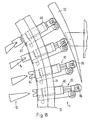
- FIGS. 7 and 8 show a wire section 38 which is gripped by the driver lugs 138 and held by the permanent magnets 140.
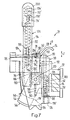
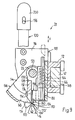
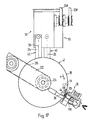
- FIGS. 7 and 8 show the stamp 130 in its rest position and in FIG. 9 in the clamp setting position 130 '.
- a spacer sleeve 142 is seated on each sleeve 124 in the region of the pin 126 and a pivot lever 144 is freely rotatably mounted between the spacer sleeve 142 and the relevant stamp arm 128.
- the two pivot levers 144 are together connecting, substantially annular segment-shaped clamp holding member 146 is arranged.
- Two mutually spaced grooves 148 are inserted on the clamp holding member 146, into which the free end regions of the punch arms 128 engage when the punch 130 is pivoted.
- a leaf spring arrangement 150 fastened to the supporting part 118 acts on the one pivot lever 144 with a counterclockwise force and presses the pivot levers 144 with the stops 152 formed on them against the supporting part 118.
- the clamp holding member 146 has one Clamp guide tab 154.
- This clip guide lug 154 is wedge-shaped and has a wedge surface, designated in the radial direction toward 154 ', which is labeled 154'.
- the plunger 80 is guided on the support part 118 so as to be displaceable in the arrow direction F.
- This direction of displacement F runs parallel to the grooves 136 in the punch arms 128 when the punch 130 is in the clamp setting position 130 '.
- the plunger 80 has at its lower end region a plunger head 158 which, when the punch 130 is in the clamp setting position 130', between the two punch arms 128 reaches into it.
- laterally projecting guide wedges 160 are formed, which when the plunger 80 is moved in the direction F from its rest position shown in FIG. 7 into the ejection position shown in FIG. 9 with the plunger 130 located in the clamp-setting position 130 'into the grooves 136.
- the plunger head 158 has a pushing groove 162 for ejecting the clamp 104 guided with its lateral arms 104 'in the grooves 136.
- the plunger 80 continues to point a groove-shaped recess 164 open towards the supporting part 118, in which a compression spring 166 is arranged, which is supported at the top on the plunger 80 and at the bottom on a bolt 168 which is fastened to the supporting part 118 and extends into the groove-shaped recess 164 (FIG. 9).
- the compression spring 166 holds the plunger 80 in the rest position indicated by solid lines in FIG. 7 and by dash-dotted lines in FIG.
- the lateral flanks 116 have at the lower end protruding lugs 170 which protrude from the plunger 130 which is in the clamp setting position 130 'and which are separated from one another by an essentially V-shaped recess 170'.
- the supporting part 118 is also mounted in a bearing arrangement 172 fastened to the supporting profile 62 (see also FIG. 6) and can be displaced in the direction of the arrow F.
- the support part 118 likewise has groove-shaped recesses 174 (FIGS. 7 and 8), into each of which a bore 176 with a thread 176 ′ opens from below.
- Further bolts 178 are arranged on the bearing arrangement 172, which engage in the groove-shaped recesses 174 and on which an additional compression spring 180 is supported on the top. At the bottom, this compression spring 180 presses against a screw 182 inserted into the thread 176 '. The compression spring 180 thus holds the support part 118 with respect to the bearing arrangement 172 in the lower rest position shown in FIG.
- a drive arrangement 184 for pivoting the shaft 120 is fastened to the one side flank 116 of the supporting part 118 shown at the bottom in FIG.
- This has a guide member 185, on which the actuating shaft 100 is also mounted displaceably in the direction of arrow F.
- a toothed rack 186 is formed on the actuating shaft 100, which meshes with a pinion 190 that is seated in a rotationally fixed manner on the shaft 120.
- a further compression spring 194 is arranged, which is supported at the top on the actuating shaft 100 and at the bottom on a pin 196 fastened to the guide member 185.
- the pin 196 penetrates a slot-shaped passage 198 in the actuating shaft 100.
- the upper end region of the actuating shaft 100 is covered by a cap-shaped sliding shoe 200, which can be displaced in the longitudinal direction with respect to the actuating shaft 100 and by means of a further pin 196 ′ fastened to the actuating shaft 100, which slide shoe 200 penetrated in a slot-like passage 198 '.
- a further compression spring 194 ' is in a bore 192' in the actuating shaft 100 which is open towards the top. used, which is supported on the slide shoe 200 and the actuating shaft 100. If the actuating shaft 100 is in its lower end position, shown in FIG. 9, and the pivot link 102 approaches the supporting part 118 even closer, the compression spring 194 'takes up this approach.
- the clamping lever 94 is pivotally mounted on the guide member 185 and is penetrated by the actuating shaft 100.
- the corresponding hole in the clamping lever 94 has only a slightly larger diameter than the thickness of the actuating shaft 100.
- the clamping lever 94 is held in a counterclockwise direction by means of a compression spring 204. In the position of the clamping lever 94 shown in FIG. 7, this holds the actuating shaft 100 in place by tilting.
- a force in the direction of arrow G by means of the release link 96, see FIG. 6, this canting is released by pivoting the clamping lever 94 clockwise and the actuating shaft 100 is released, which is displaced upward by the compression spring 194.
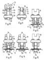
- FIGS. 10 to 15 show parts of the stitching head 28 during various phases of a work cycle.
- the corresponding parts of the stitching head 28 in these figures are numbered the same as in Figures 7 to 9 and are therefore not explained in more detail.
- the support 14 (FIGS. 12 to 15)
- the bending plunger 114 is guided so that it can be moved up and down in the direction of the arrow E.
- Two benders 206 pivotably supported on the support 14 are supported on it, cf. also FIG. 6.
- the stamp 130 is in its rest position, which is also shown in FIGS. 7 and 8.
- the plunger 80 with its plunger head 158 is also in the rest position.
- the stapling head 28 moves past the feed wheel 42 of the wire section dispenser 30 (cf. FIG. 1) and takes over a wire section 38 from the holding member 44 of the feed wheel 42 by means of entrainment lugs 138.
- This wire section 38 is made by means of the permanent magnets, not shown in this figure 140 held on the punch arms 128.
- the web connecting the two punch arms 128 to one another is shown at 132.
- the stitching head 28 is located in the area of the die 98 (see FIG. 5), the stamp 130 still being in its rest position.
- the wire section 38 is bent into a U-shape to form a clamp 104, the lateral arms 104 ′ sliding into the grooves 136 of the punch arms 128.
- the actuating shaft 100 is brought into its lower end position shown in FIG. 9, as a result of which the plunger 130 is pivoted into the clamp setting position 130 ′ shown in FIGS. 9 and 12.
- the punch arms 128 engage in the area 148 of their thickening 134 in the grooves 148 of the clamp holding member 146, as a result of which the lateral arms 104 ′ are held in the grooves 136.
- the plunger head 158 of the plunger 80 is also in the clamp setting position 130 'of the plunger 130 between the two plunger arms 128, but in the area between the shaft 120 and the thickened portions 134.
- the tappet link 78 acts on the tappet 80, the tappet 80 is pushed against the support 14 in the direction of the arrow F, as shown in FIG.
- the guide wedges 160 formed laterally on the plunger head 158 slide into the grooves 136 of the stamp arms 128 located in the clamp-setting position 130 '.
- the clamp 104 is ejected from the stamp 130 with the push groove 162, the lateral arms 104' simultaneously being pressed onto the support 14 stored printed sheets 20 are pushed.
- the plunger 80 When the plunger 80 is lowered, it slides on the wedge surface 154 'of the clip guide lug 154, as a result of which the clip holding member 146 attached to the pivot levers 144 is pivoted clockwise (see FIG. 9).
- the clip guide lug 154 holds the lateral arms 104 'of the clip 104 in the grooves 136 until the clip 104 is inserted into the printed sheets 20 and the clip guide lug 154 is pivoted out of the area of the grooves 136.
- the bending units 206 are pivoted upward, which has the consequence that the portions of the lateral arms 104 'projecting into the region of the bending units 206 are bent toward one another (FIG. 14).
- the plunger 80 is still held in the lower end position by the plunger link 78.
- the plunger 80 After the plunger 80 has run out from the plunger link 78, it moves back into the upper rest position under the force of the compression spring 166, as shown in FIG.
- the bending machine 206 is also pivoted back into its original position.
- the actuating shaft 100 is released by the clamping lever 94, which pivots of the stamp 130 back into the rest position.
- FIGS. 16 and 17 the wire section dispensers 30 indicated in FIG. 5 and assigned to the two stitching head arrangements 24 are shown enlarged. Each of these wire section dispensers 30 is constructed in the same way as the wire section dispenser 30 shown in FIG. 1.
- the cutting device 32 is driven by a rotating toothed belt 208.
- a pair of conveyor rollers 210 conveys the wire 36 clamped between them step by step in the direction of the arrow H.
- a cutting knife 212 which can be moved up and down in the direction of the arrow I separates a wire section 38 from the wire 36 by lowering after each conveying movement of the wire 36.
- the magazine 40 Downstream of the cutting knife 212, the magazine 40 is arranged below the cutting device 32. It has an essentially slit-shaped stacking shaft 214 running approximately in the vertical direction, in which the wire sections 38 falling therein can be stacked one above the other with a longitudinal extension running essentially in the horizontal direction.
- a pre-stacking device 216 with a tongue 218 which can be moved into the area of the stacking shaft 214 and can be withdrawn from it.
- a number of wire sections 38 separated from the wire 36 by the cutting device 32 are stacked.
- these stacked wire sections 38 then fall together into the stacking shaft 214. This prevents the wire sections from being erected and tilted 38 during the free fall and guarantees a clean stacking of the wire sections 38 in the stacking shaft 214.
- the two conveyor wheels 42 arranged below the magazines 40 are non-rotatably seated on a common bearing shaft 224 which is rotatably mounted on a pair of support levers 222.
- the two conveyor wheels 42 are driven to rotate in the direction of arrow V by a drive device 228 which acts on the bearing shaft 224 via a drive belt 226.
- Each conveyor wheel 42 has two parallel disks 230 spaced apart from one another, between which the holding members 44 are arranged along the circumference at certain intervals.
- the holding members are U-shaped and have at their free ends which are directed outward in the radial direction over the periphery of the disks 230, protruding flanks 232.
- a permanent magnet arrangement is provided on the holding members 44 in order to hold the wire sections 38 released from the stacking shaft 214 by the driver flanks 232 as they pass the magazine 40.
- the stitching heads 28 are spaced further apart than the holding members 44. Accordingly, the peripheral speed of the feed wheels 42 is lower than the rotational speed of the stitching heads 28, so that the next stitching head 28 meets the next holding member 44.
- the stapling head 28 thus runs past the holding member 44 and pulls with the ones arranged on the punch arms 128 Driver lugs 138 from the holding member 44 the wire section 38 in question and holds it by means of the permanent magnet 140 on the punch 130.
- the holding members 44 are arranged in a generally known manner to be displaceable and spring-loaded in the radial direction in order to be able to take up tolerances and to ensure secure takeover of the wire sections 38 from the stacking shaft 214 and transfer to the stitching heads 28.
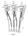
- the initial region of the driver link 92 is shown in FIG. 18 in the direction of rotation U.
- the follower rollers 86 of the drivers 82 run onto the driver link 92, which has the consequence that the drivers 82, which are guided on the holding part 68 in a radial direction, are lowered onto the relevant supports 14 of the collecting drum 10.
- the V-shaped driver profiles 84 encompass the supports 14. This has the consequence that the stitching heads 28 arranged on the support profile 62 and not shown in FIG. 18 are precisely aligned with respect to the associated support 14 or the printed sheets 20 placed thereon. Furthermore, the drive of the holding arrangement 52 takes place exclusively by being carried along by the catches 82 which are in engagement with the supports 14.
- the catches 82 are lowered onto the supports 14 only in the upper region of the orbit of the collecting drum 10, so that the means of the Stapling station 22 stapled printed sheets 20 in the direction of the axis of rotation 12 through the now Pads 14 and driver profiles 84 spaced apart from one another can be conveyed away, or the printed sheets 20 to be stapled can be brought into the area of the stapling station 22.
- a stitching head 28 is now traced in the course of one revolution of the holding arrangement 52, starting at the wire section dispenser 30.
- the stitching heads 28 pass the wire section dispenser, they are in their outer rest position, seen in the radial direction, in which they are spaced from the supports 14.
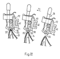
- the punches 130 are pivoted back into the rest position, so that the free ends of the punch arms 128 are directed towards the outside when viewed in the radial direction.
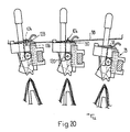
- the stapling head 28 runs past the relevant holding member 44 of the feed wheel 42, the wire section 38 fed from the holding member 44 is detached from it by the driving lugs 138 and taken along (FIG. 19).
- the stitching heads 28 reach the area of the die 98, as shown in FIG. 20. Seen in the direction of the arrow U, the distance between the link-shaped die 98 and the shaft 120 decreases, so that when the punch 130 is in the rest position, the wire section 38 in question is bent into a clamp 104 and pushed into the grooves 136 of the punch arms 128 (FIG. 20 ). When the swivel link 102 is reached, the sliding shoe 200 runs onto it, which has the consequence that the actuating shaft 100 is pressed inward in the direction of arrow F in the radial direction. This translational movement of the actuating shaft 100 is via the pinion 190 in a pivoting movement of the shaft 120 implemented.
- the plunger 80 slides back into its outer rest position, as seen in the radial direction, under the action of the compression spring 166 and the distance from the supporting part 118 which increases in the end region of the plunger link 78.
- the stitching heads 28 are now ready to take over a new wire from the wire section dispenser 30.
- the collecting drum 10 continues to rotate, the stapled printed sheets 20 are now conveyed in the direction of the axis of rotation 12 away from the area of the stapling station 22 to a removal station (not shown).
- the wire section preparation By separating the wire section preparation from the stitching heads 28, these can be constructed very simply. In addition, only one wire section dispenser 30 is required per stitching head arrangement 24, which reduces the expenditure to a minimum. In addition, the wire section dispenser 30 can be removed from the area in which the clips 104 are placed in the printed sheets 20. As a result, there is sufficient time for the preparation of the clips 104 in the area between the wire section dispenser 30 and the clip setting area. In the case of stapling heads with pivotable stamps 130, the staples 104 can be prepared in a position different from the staple setting position 130 ', which means that the various functions of the stapling heads 28 are spatially separated from one another; this in turn has the consequence that the stitching heads 28 are simple in construction with small dimensions.
- the die can be provided for bending the wire section 38 into a clamp 104 on each stitching head 28 itself. This has an eccentric shape with respect to the shaft, so that in the course of the pivoting movement of the plunger 130 from its rest division into the stapling division 130 'the bracket 104 is formed.
- Such a die could be formed on the clip holding member 146 clockwise in particular as a change.
- the drivers are arranged on the stitching heads; so it is quite conceivable that the pressing lugs 170 serve as drivers.
- a separate drive for the stapling station 22 is no longer necessary and synchronization problems between the rotation of the collecting drum 10 and the stapling head arrangements 24 have been eliminated.
- the traction element or the holding arrangement 52 can be driven in a rotating manner by means of its own drive motor. It is also conceivable that the wire section dispenser has an exchangeable magazine, or that the wire sections are fed directly to the stitching heads by the cutting device.
- the punches 130 can be in a wire takeover position that is different from the rest position for the wire takeover.
- the wire takeover position does not correspond to the clamp setting position 130 '.
- the wire sections 38 run essentially parallel to the pivot axis 122.
- Stapling heads which are particularly suitable for devices according to the invention for collecting printed sheets are described in the simultaneous EP-A-0 399 322 and US-A-5,098,002.
- a device in which a stitching head is permanently assigned to each support, also allows the stitching heads of a stitching head arrangement to be mutually offset in the longitudinal direction of the supports. For example, every second stitching head can be slightly offset with respect to the other stitching heads arranged in one plane; the two groups of stitching heads then advantageously each pass their own wire section dispenser. When the stapled sheets are stacked, not all of the staples come to lie on top of one another.
Landscapes
- Engineering & Computer Science (AREA)
- Textile Engineering (AREA)
- Mechanical Engineering (AREA)
- Folding Of Thin Sheet-Like Materials, Special Discharging Devices, And Others (AREA)
- Sewing Machines And Sewing (AREA)
- Pile Receivers (AREA)
- Collation Of Sheets And Webs (AREA)
- Dovetailed Work, And Nailing Machines And Stapling Machines For Wood (AREA)
- Insulated Conductors (AREA)
Claims (10)
- Dispositif pour assembler des imprimés pliés, avec des supports (14) en forme de selle tournant le long d'une orbite fermée, dotés d'une étendue en longueur mutuellement parallèle, et essentiellement perpendiculaire au sens de rotation (U), dans une section au moins de l'orbite, supports sur lesquels peuvent être déposés les uns sur les autres, à califourchon, des imprimés (20) au moyen de deux postes d'alimentation, au moins, distants l'un de l'autre, avec un poste d'agrafage (22) disposé en aval des postes d'alimentation, prévu dans la section citée de l'orbite, et comportant un agencement de têtes de piquage (24), au moins, avec plusieurs têtes de piquage (28) pour la pose d'agrafes (104) dans les imprimés (20) déposés sur les supports (14), ces têtes étant essentiellement disposées les unes derrière les autres à distance des supports (14), parallèles entre eux dans leur étendue en longueur, étant essentiellement mobiles dans un plan transversal aux supports (14), et se déplaçant lors de l'agrafage en synchronisme avec les supports (14), avec des moyens pour le formage des agrafes (104) à partir de sections de fils (38) essentiellement rectilignes, maintenues par les têtes de piquage (28), et avec un poste d'évacuation pour acheminer les imprimés agrafés (20), caractérisé en ce que les têtes de piquage (28) sont disposées et tournent le long d'une trajectoire fermée (26), passant devant un distributeur de sections de fils (30) et devant l'orbite des supports (14), avec une vitesse de rotation essentiellement égale et tournent devant l'orbite dans le même sens (U, U') que les supports (14), en ce que le distributeur de sections de fils (30) est disposé sur l'autre côté de l'orbite des supports (14), par rapport à la trajectoire (26), et en ce que chaque tête de piquage (28) présente des moyens réalisés pour reprendre une section de fil (38) du distributeur (30), dans leur position de reprise tournée vers le distributeur (30), et ammener cette section dans une position de pose des agrafes (130'), tournée vers l'orbite des supports (14).
- Dispositif suivant la revendication 1, caractérisé en ce que chaque tête de piquage (28) présente un poinçon (130), pivotant autour d'un axe (122) essentiellement perpendiculaire au sens de rotation (U, U') de la tête de piquage (28), d'une position de repos dans une position de pose des agrafes (130'), et inversement, pour reprendre du distributeur (30) la section de fil (38) au moyen du poinçon (130) en position de reprise, qui correspond de préférence à la position de repos, et amener cette section en position de pose des agrafes (130).
- Dispositif suivant l'une des revendications 1 et 2, caractérisé en ce que le distributeur de sections de fils (30) est distant de la zone de pose (D, D') des agrafes (104), dans le sens de la trajectoire (26).
- Dispositif suivant la revendication 3, caractérisé en ce que les moyens de formage des agrafes (104) présentent une matrice (98), agissant sur les sections de fils (38) dans l'une des zones disposées en aval du distributeur de sections de fils (30), vu dans le sens de rotation (U, U') des têtes de piquage (28).
- Dispositif suivant les revendications 2 et 4, caractérisé en ce que la matrice présente, par tête de piquage, une coulisse de cintrage disposée sur cette dernière et agissant sur la section de fil au cours du mouvement de pivotement du poinçon de la position de reprise dans la position de pose des agrafes.
- Dispositif suivant les revendications 2 et 4, caractérisé en ce que la matrice présente une coulisse de cintrage (98) prévue le long de la trajectoire (26), entre le distributeur de sections de fils (30) et la zone de pose des agrafes (D, D'), pour le formage d'une agrafe (104) à partir de la section de fil (38) supportée par le poinçon (130), essentiellement maintenu sans possibilité de rotation dans la zone de la coulisse de cintrage (98).
- Dispositif suivant l'une quelconque des revendications 1 à 6, caractérisé en ce que les têtes de piquage (28), pour la pose des agrafes (104), tournent avec les supports (14), le long de l'orbite de ces derniers, dans une zone étendue (D) qui leur est commune.
- Dispositif suivant l'une quelconque des revendications 1 à 6, caractérisé en ce que la trajectoire (26) a essentiellement une réalisation en forme de cercle.
- Dispositif suivant l'une quelconque des revendications 1 à 8, caractérisé en ce que les supports (14) sont disposés à la manière d'un tambour autour d'un axe de rotation commun (12).
- Dispositif suivant l'une quelconque des revendications 1 à 9, caractérisé en ce que des organes de pliage (206) sont prévus dans les supports (14), pour plier les bras latéraux (104') des agrafes (104), poussés au travers des imprimés (20).
Applications Claiming Priority (3)
| Application Number | Priority Date | Filing Date | Title |
|---|---|---|---|
| CH1964/89 | 1989-05-25 | ||
| CH196489 | 1989-05-25 | ||
| EP90108961A EP0399317B1 (fr) | 1989-05-25 | 1990-05-12 | Appareil pour grouper et coudre des feuilles imprimées et pliées |
Related Parent Applications (3)
| Application Number | Title | Priority Date | Filing Date |
|---|---|---|---|
| EP90108961A Division-Into EP0399317B1 (fr) | 1989-05-25 | 1990-05-12 | Appareil pour grouper et coudre des feuilles imprimées et pliées |
| EP90108961A Division EP0399317B1 (fr) | 1989-05-25 | 1990-05-12 | Appareil pour grouper et coudre des feuilles imprimées et pliées |
| EP90108961.5 Division | 1990-05-12 |
Publications (2)
| Publication Number | Publication Date |
|---|---|
| EP0569887A1 EP0569887A1 (fr) | 1993-11-18 |
| EP0569887B1 true EP0569887B1 (fr) | 1995-08-09 |
Family
ID=4222731
Family Applications (3)
| Application Number | Title | Priority Date | Filing Date |
|---|---|---|---|
| EP90108961A Expired - Lifetime EP0399317B1 (fr) | 1989-05-25 | 1990-05-12 | Appareil pour grouper et coudre des feuilles imprimées et pliées |
| EP93107489A Expired - Lifetime EP0569887B1 (fr) | 1989-05-25 | 1990-05-12 | Dispositif pour assembler et brocher des produits imprimés pliés |
| EP91119133A Expired - Lifetime EP0476718B2 (fr) | 1989-05-25 | 1990-05-12 | Dispositif pour piquer des produits d'imprimerie à plusieurs parties |
Family Applications Before (1)
| Application Number | Title | Priority Date | Filing Date |
|---|---|---|---|
| EP90108961A Expired - Lifetime EP0399317B1 (fr) | 1989-05-25 | 1990-05-12 | Appareil pour grouper et coudre des feuilles imprimées et pliées |
Family Applications After (1)
| Application Number | Title | Priority Date | Filing Date |
|---|---|---|---|
| EP91119133A Expired - Lifetime EP0476718B2 (fr) | 1989-05-25 | 1990-05-12 | Dispositif pour piquer des produits d'imprimerie à plusieurs parties |
Country Status (10)
| Country | Link |
|---|---|
| EP (3) | EP0399317B1 (fr) |
| JP (2) | JP2652077B2 (fr) |
| AT (1) | ATE126130T1 (fr) |
| AU (1) | AU622556B2 (fr) |
| CA (1) | CA2017443C (fr) |
| DD (1) | DD294677A5 (fr) |
| DE (3) | DE59003842D1 (fr) |
| ES (2) | ES2047193T3 (fr) |
| FI (1) | FI98352C (fr) |
| RU (2) | RU2057029C1 (fr) |
Families Citing this family (22)
| Publication number | Priority date | Publication date | Assignee | Title |
|---|---|---|---|---|
| ES2042139T3 (es) | 1989-05-25 | 1993-12-01 | Ferag Ag | Aparato encuadernador. |
| EP0473902B1 (fr) * | 1990-08-06 | 1995-10-11 | Ferag AG | Dispositif d'agrafage de produits imprimés composés |
| ES2077330T3 (es) * | 1991-12-13 | 1995-11-16 | Ferag Ag | Dispositivo para el grapado con alambre de productos de imprenta de varias piezas. |
| JP3415645B2 (ja) * | 1992-04-14 | 2003-06-09 | グラプハ−ホルディング・アクチエンゲゼルシヤフト | 折り目をつけられたシート状印刷物を集めて綴じるための装置 |
| CH686078A5 (de) * | 1992-11-30 | 1995-12-29 | Grapha Holding Ag | Vorrichtung zum Heften von auf sich folgenden Auflagen einer umlaufenden Fordereinrichtung rittlings ubereinander abgelegten, bogenartigen Druckprodukten. |
| DK0606555T3 (da) * | 1993-01-11 | 1997-10-13 | Ferag Ag | Samlehæftemaskine til trykprodukter,der består af foldede trykarkkark |
| SE506108C2 (sv) * | 1993-02-18 | 1997-11-10 | Tolerans Ingol Sweden Ab | Anordning för att applicera häftklammer till ett material |
| US5570832A (en) * | 1993-06-21 | 1996-11-05 | Grafa-Holding Ag | Apparatus for stapling sequential printed sheets positioned straddled one above the other |
| EP0659586B1 (fr) * | 1993-12-21 | 1998-05-06 | Grapha-Holding Ag | Procédé pour délivrer un ensemble de feuilles imprimées avec des encarts |
| DE59403252D1 (de) * | 1994-01-10 | 1997-08-07 | Ferag Ag | Vorrichtung zum Klebheften von Druckereierzeugnissen |
| ES2115991T3 (es) * | 1994-03-25 | 1998-07-01 | Ferag Ag | Instalacion para la union por encolado de productos de imprenta. |
| EP0691215B1 (fr) | 1994-07-06 | 1997-08-20 | Ferag AG | Dispositif de piquage au fil métallique de produits imprimés |
| WO1996036492A1 (fr) * | 1995-05-20 | 1996-11-21 | Koenig & Bauer-Albert Ag | Dispositif de brochage |
| EP0981450B1 (fr) | 1997-05-07 | 2002-10-23 | Ferag AG | Dispositif d'agrafage longitudinal de produits imprimes en plusieurs parties |
| DK1245406T3 (da) * | 2001-03-29 | 2008-09-01 | Grapha Holding Ag | Indretning til hæftning med klammer af ryggen på trykkeriprodukter, der er dannet af falsede trykte ark |
| DE50110701D1 (de) * | 2001-06-28 | 2006-09-21 | Grapha Holding Ag | Verfahren zur Herstellung eines aus mehreren Druckprodukten bestehendes geheftetes Druckerzeugnis und Vorrichtung zur Durchführung des Verfahrens. |
| US6969342B2 (en) | 2002-02-28 | 2005-11-29 | Hewlett-Packard Development Company, L.P. | System for handling folded sheet material |
| US6981830B2 (en) * | 2002-02-28 | 2006-01-03 | Hewlett-Packard Development Company, L.P. | Pivotable collecting device |
| US7033123B2 (en) * | 2002-02-28 | 2006-04-25 | Hewlett-Packard Development Company, L.P. | Booklet maker |
| US7581724B2 (en) | 2002-11-09 | 2009-09-01 | Ferag Ag | Device for collecting and processing folded printed products |
| CA2573175A1 (fr) * | 2006-01-13 | 2007-07-13 | Ferag Ag | Methode et installation pour le traitement de produits imprimes en cours de transport |
| CN116373302B (zh) * | 2021-06-28 | 2024-10-01 | 上海轮廓科技有限公司 | 材料馈送机构、多料单元及3d打印系统 |
Family Cites Families (13)
| Publication number | Priority date | Publication date | Assignee | Title |
|---|---|---|---|---|
| GB740079A (en) * | 1952-01-08 | 1955-11-09 | Crabtree & Sons Ltd R | Improvements in stapling mechanism |
| US2966681A (en) * | 1957-10-09 | 1961-01-03 | Lee R Campbell | Feeding mechanism for fastener driving devices |
| CH459145A (de) * | 1968-01-23 | 1968-07-15 | Leipziger Buchbindereimaschine | Sammeldrahtheftmaschine |
| JPS565680B2 (fr) * | 1972-05-04 | 1981-02-06 | ||
| DD138525A1 (de) * | 1978-09-04 | 1979-11-07 | Winfried Boettcher | Einrichtung zum einstechen von fadenklammern in falzbogen |
| US4315588A (en) * | 1980-01-21 | 1982-02-16 | Faltin Hans G | High speed on-line stitcher for signatures and webs |
| DE3362515D1 (en) * | 1982-06-01 | 1986-04-17 | Ferag Ag | Device for collecting folded printing sheets |
| US4478398A (en) * | 1982-07-16 | 1984-10-23 | Stobb, Inc. | System for routing a signature for stitching using a lift finger |
| JPS60240497A (ja) * | 1984-05-16 | 1985-11-29 | 凸版印刷株式会社 | 製本針金綴不良検査装置 |
| CH667621A5 (de) * | 1985-06-04 | 1988-10-31 | Grapha Holding Ag | Sammelhefter. |
| IT1185103B (it) * | 1985-06-14 | 1987-11-04 | Cerutti Spa Off Mec | Cucitrice perfezionata per seganture |
| US4792077A (en) * | 1987-04-27 | 1988-12-20 | Custom-Bilt Machinery, Inc. | Apparatus for stapling and creasing paper articles in transit |
| ES2042139T3 (es) * | 1989-05-25 | 1993-12-01 | Ferag Ag | Aparato encuadernador. |
-
1990
- 1990-05-12 DE DE90108961T patent/DE59003842D1/de not_active Expired - Fee Related
- 1990-05-12 AT AT93107489T patent/ATE126130T1/de not_active IP Right Cessation
- 1990-05-12 ES ES90108961T patent/ES2047193T3/es not_active Expired - Lifetime
- 1990-05-12 EP EP90108961A patent/EP0399317B1/fr not_active Expired - Lifetime
- 1990-05-12 EP EP93107489A patent/EP0569887B1/fr not_active Expired - Lifetime
- 1990-05-12 DE DE59009519T patent/DE59009519D1/de not_active Expired - Fee Related
- 1990-05-12 EP EP91119133A patent/EP0476718B2/fr not_active Expired - Lifetime
- 1990-05-12 ES ES93107489T patent/ES2076816T3/es not_active Expired - Lifetime
- 1990-05-12 DE DE91119133T patent/DE59004157D1/de not_active Expired - Fee Related
- 1990-05-23 DD DD90340955A patent/DD294677A5/de not_active IP Right Cessation
- 1990-05-24 FI FI902605A patent/FI98352C/fi not_active IP Right Cessation
- 1990-05-24 CA CA002017443A patent/CA2017443C/fr not_active Expired - Fee Related
- 1990-05-24 AU AU55907/90A patent/AU622556B2/en not_active Ceased
- 1990-05-25 RU SU904830293A patent/RU2057029C1/ru not_active IP Right Cessation
- 1990-05-25 JP JP2136951A patent/JP2652077B2/ja not_active Expired - Fee Related
-
1992
- 1992-01-23 RU SU925010649A patent/RU2071919C1/ru not_active IP Right Cessation
-
1994
- 1994-05-11 JP JP6121978A patent/JP2646191B2/ja not_active Expired - Fee Related
Also Published As
| Publication number | Publication date |
|---|---|
| JP2646191B2 (ja) | 1997-08-25 |
| CA2017443A1 (fr) | 1990-11-25 |
| EP0399317A1 (fr) | 1990-11-28 |
| DE59004157D1 (de) | 1994-02-17 |
| RU2071919C1 (ru) | 1997-01-20 |
| CA2017443C (fr) | 2000-08-22 |
| EP0399317B1 (fr) | 1993-12-15 |
| DE59009519D1 (de) | 1995-09-14 |
| EP0569887A1 (fr) | 1993-11-18 |
| EP0476718B1 (fr) | 1994-01-05 |
| EP0476718A1 (fr) | 1992-03-25 |
| EP0476718B2 (fr) | 2001-05-09 |
| AU622556B2 (en) | 1992-04-09 |
| JP2652077B2 (ja) | 1997-09-10 |
| RU2057029C1 (ru) | 1996-03-27 |
| FI98352C (fi) | 1997-06-10 |
| DE59003842D1 (de) | 1994-01-27 |
| JPH0752578A (ja) | 1995-02-28 |
| FI902605A0 (fi) | 1990-05-24 |
| DD294677A5 (de) | 1991-10-10 |
| JPH0321497A (ja) | 1991-01-30 |
| ES2047193T3 (es) | 1994-02-16 |
| ATE126130T1 (de) | 1995-08-15 |
| ES2076816T3 (es) | 1995-11-01 |
| AU5590790A (en) | 1990-11-29 |
| FI98352B (fi) | 1997-02-28 |
Similar Documents
| Publication | Publication Date | Title |
|---|---|---|
| EP0399317B1 (fr) | Appareil pour grouper et coudre des feuilles imprimées et pliées | |
| EP0399322B1 (fr) | Appareil de brochage | |
| EP0675005B1 (fr) | Dispositif pour la reliure adhésive de produits imprimés | |
| EP0623542A1 (fr) | Dispositif pour empiler un chant de feuilles imprimées | |
| EP0366038B1 (fr) | Dispositif pour plier en zigzag et empiler une bande de matériau | |
| EP0473902B1 (fr) | Dispositif d'agrafage de produits imprimés composés | |
| DE2835308A1 (de) | Verfahren und vorrichtung zum banderolieren von duennem blattgut | |
| DE60004431T2 (de) | Verfahren und Vorrichtung zur Formung einer Reifenverstärkungslage | |
| EP0336062B1 (fr) | Machine à insérer | |
| DE3217038A1 (de) | Verfahren und vorrichtung zum stanzschneiden von bahn- oder plattenfoermigem schneidgut | |
| DE2404667B2 (de) | Vorrichtung zum Binden am Rand gelochter Blattstapel mittels einer Drahtwendel | |
| EP0712736B1 (fr) | Méthode pour la fabrication de livres, brochures ou similaires reliés par adhésif | |
| EP0418529A2 (fr) | Appareil pour limiter des feuilles imprimées à trois côtés | |
| DE2508745A1 (de) | Vorrichtung zum aufstauen vereinzelt vorgeschobener papierboegen zu stapeln und zum weitertransportieren dieser stapel | |
| EP0872443B1 (fr) | Dispositif pour former une pile partielle s'étandant perpendiculèrement aux feuilles imprimées rangées sur la tranche et une à côté de l'autre | |
| EP0250758A1 (fr) | Dispositif de pliage et de convoyage | |
| DE1561141A1 (de) | Vorrichtung zum OEffnen eines mehrblaettrigen Papiererzeugnisses an einer durch Reibungsminderung vorbestimmten Stelle und zum Einfuehren einer Beilage in das geoeffnete Erzeugnis | |
| EP1943173B1 (fr) | Procede et dispositif pour transferer des produits plats d'une pile de produits a une bande transporteuse | |
| EP0023985B1 (fr) | Dispositif de brochage pour machines d'impression | |
| EP0662440B1 (fr) | Dispositif pour l'agrafage par adhésif de produits imprimés | |
| EP0586926A2 (fr) | Dispositif pour couper et agrafer des produits imprimés à plusieurs couches dans des appareils de pliage | |
| EP0751905B1 (fr) | Procede et dispositif pour le travail en paquets de feuilles coincidentes d'un materiau plat | |
| EP1348571B1 (fr) | Dispositif pour relier des éléments plats empilés | |
| DE2242577A1 (de) | Vorrichtung zum klammern und falten mehrerer uebereinanderliegender papierbogen | |
| DE3444576A1 (de) | Verfahren und vorrichtung zur herstellung von buechern, insbesondere taschenbuechern, broschueren und zeitschriften |
Legal Events
| Date | Code | Title | Description |
|---|---|---|---|
| PUAI | Public reference made under article 153(3) epc to a published international application that has entered the european phase |
Free format text: ORIGINAL CODE: 0009012 |
|
| AC | Divisional application: reference to earlier application |
Ref document number: 399317 Country of ref document: EP |
|
| AK | Designated contracting states |
Kind code of ref document: A1 Designated state(s): AT CH DE ES GB IT LI SE |
|
| 17P | Request for examination filed |
Effective date: 19931015 |
|
| 17Q | First examination report despatched |
Effective date: 19941006 |
|
| GRAA | (expected) grant |
Free format text: ORIGINAL CODE: 0009210 |
|
| ITF | It: translation for a ep patent filed | ||
| AC | Divisional application: reference to earlier application |
Ref document number: 399317 Country of ref document: EP |
|
| AK | Designated contracting states |
Kind code of ref document: B1 Designated state(s): AT CH DE ES GB IT LI SE |
|
| REF | Corresponds to: |
Ref document number: 126130 Country of ref document: AT Date of ref document: 19950815 Kind code of ref document: T |
|
| GBT | Gb: translation of ep patent filed (gb section 77(6)(a)/1977) |
Effective date: 19950807 |
|
| REF | Corresponds to: |
Ref document number: 59009519 Country of ref document: DE Date of ref document: 19950914 |
|
| REG | Reference to a national code |
Ref country code: ES Ref legal event code: FG2A Ref document number: 2076816 Country of ref document: ES Kind code of ref document: T3 |
|
| PLBE | No opposition filed within time limit |
Free format text: ORIGINAL CODE: 0009261 |
|
| 26N | No opposition filed | ||
| PGFP | Annual fee paid to national office [announced via postgrant information from national office to epo] |
Ref country code: AT Payment date: 20010427 Year of fee payment: 12 |
|
| PGFP | Annual fee paid to national office [announced via postgrant information from national office to epo] |
Ref country code: ES Payment date: 20010514 Year of fee payment: 12 |
|
| REG | Reference to a national code |
Ref country code: GB Ref legal event code: IF02 |
|
| PG25 | Lapsed in a contracting state [announced via postgrant information from national office to epo] |
Ref country code: AT Free format text: LAPSE BECAUSE OF NON-PAYMENT OF DUE FEES Effective date: 20020512 |
|
| PG25 | Lapsed in a contracting state [announced via postgrant information from national office to epo] |
Ref country code: ES Free format text: LAPSE BECAUSE OF NON-PAYMENT OF DUE FEES Effective date: 20020513 |
|
| REG | Reference to a national code |
Ref country code: ES Ref legal event code: FD2A Effective date: 20030611 |
|
| REG | Reference to a national code |
Ref country code: CH Ref legal event code: PFA Owner name: FERAG AG Free format text: FERAG AG#ZUERICHSTRASSE 74#8340 HINWIL (CH) -TRANSFER TO- FERAG AG#PATENTABTEILUNG Z. H. MARKUS FELIX ZUERICHSTRASSE 74#8340 HINWIL (CH) |
|
| PG25 | Lapsed in a contracting state [announced via postgrant information from national office to epo] |
Ref country code: IT Free format text: LAPSE BECAUSE OF NON-PAYMENT OF DUE FEES;WARNING: LAPSES OF ITALIAN PATENTS WITH EFFECTIVE DATE BEFORE 2007 MAY HAVE OCCURRED AT ANY TIME BEFORE 2007. THE CORRECT EFFECTIVE DATE MAY BE DIFFERENT FROM THE ONE RECORDED. Effective date: 20050512 |
|
| PGFP | Annual fee paid to national office [announced via postgrant information from national office to epo] |
Ref country code: DE Payment date: 20080523 Year of fee payment: 19 Ref country code: CH Payment date: 20080521 Year of fee payment: 19 |
|
| PGFP | Annual fee paid to national office [announced via postgrant information from national office to epo] |
Ref country code: SE Payment date: 20080513 Year of fee payment: 19 |
|
| PGFP | Annual fee paid to national office [announced via postgrant information from national office to epo] |
Ref country code: GB Payment date: 20080522 Year of fee payment: 19 |
|
| REG | Reference to a national code |
Ref country code: CH Ref legal event code: PL |
|
| GBPC | Gb: european patent ceased through non-payment of renewal fee |
Effective date: 20090512 |
|
| PG25 | Lapsed in a contracting state [announced via postgrant information from national office to epo] |
Ref country code: LI Free format text: LAPSE BECAUSE OF NON-PAYMENT OF DUE FEES Effective date: 20090531 Ref country code: CH Free format text: LAPSE BECAUSE OF NON-PAYMENT OF DUE FEES Effective date: 20090531 |
|
| PG25 | Lapsed in a contracting state [announced via postgrant information from national office to epo] |
Ref country code: GB Free format text: LAPSE BECAUSE OF NON-PAYMENT OF DUE FEES Effective date: 20090512 |
|
| PG25 | Lapsed in a contracting state [announced via postgrant information from national office to epo] |
Ref country code: DE Free format text: LAPSE BECAUSE OF NON-PAYMENT OF DUE FEES Effective date: 20091201 |
|
| PG25 | Lapsed in a contracting state [announced via postgrant information from national office to epo] |
Ref country code: SE Free format text: LAPSE BECAUSE OF NON-PAYMENT OF DUE FEES Effective date: 20090513 |