EP0570202A1 - Methode und Gerät für magnetische Aufnahme und/oder Wiedergabe - Google Patents
Methode und Gerät für magnetische Aufnahme und/oder Wiedergabe Download PDFInfo
- Publication number
- EP0570202A1 EP0570202A1 EP93303656A EP93303656A EP0570202A1 EP 0570202 A1 EP0570202 A1 EP 0570202A1 EP 93303656 A EP93303656 A EP 93303656A EP 93303656 A EP93303656 A EP 93303656A EP 0570202 A1 EP0570202 A1 EP 0570202A1
- Authority
- EP
- European Patent Office
- Prior art keywords
- recording
- reproducing
- magnetic tape
- format
- helical
- Prior art date
- Legal status (The legal status is an assumption and is not a legal conclusion. Google has not performed a legal analysis and makes no representation as to the accuracy of the status listed.)
- Granted
Links
Images




Classifications
-
- G—PHYSICS
- G11—INFORMATION STORAGE
- G11B—INFORMATION STORAGE BASED ON RELATIVE MOVEMENT BETWEEN RECORD CARRIER AND TRANSDUCER
- G11B5/00—Recording by magnetisation or demagnetisation of a record carrier; Reproducing by magnetic means; Record carriers therefor
- G11B5/48—Disposition or mounting of heads or head supports relative to record carriers ; arrangements of heads, e.g. for scanning the record carrier to increase the relative speed
- G11B5/56—Disposition or mounting of heads or head supports relative to record carriers ; arrangements of heads, e.g. for scanning the record carrier to increase the relative speed with provision for moving the head support for the purpose of adjusting the position of the head relative to the record carrier, e.g. manual adjustment for azimuth correction or track centering
-
- H—ELECTRICITY
- H04—ELECTRIC COMMUNICATION TECHNIQUE
- H04N—PICTORIAL COMMUNICATION, e.g. TELEVISION
- H04N5/00—Details of television systems
- H04N5/76—Television signal recording
- H04N5/78—Television signal recording using magnetic recording
- H04N5/782—Television signal recording using magnetic recording on tape
- H04N5/7824—Television signal recording using magnetic recording on tape with rotating magnetic heads
- H04N5/7826—Television signal recording using magnetic recording on tape with rotating magnetic heads involving helical scanning of the magnetic tape
- H04N5/78263—Television signal recording using magnetic recording on tape with rotating magnetic heads involving helical scanning of the magnetic tape for recording on tracks inclined relative to the direction of movement of the tape
-
- G—PHYSICS
- G11—INFORMATION STORAGE
- G11B—INFORMATION STORAGE BASED ON RELATIVE MOVEMENT BETWEEN RECORD CARRIER AND TRANSDUCER
- G11B5/00—Recording by magnetisation or demagnetisation of a record carrier; Reproducing by magnetic means; Record carriers therefor
- G11B5/008—Recording on, or reproducing or erasing from, magnetic tapes, sheets, e.g. cards, or wires
- G11B5/00813—Recording on, or reproducing or erasing from, magnetic tapes, sheets, e.g. cards, or wires magnetic tapes
- G11B5/00878—Recording on, or reproducing or erasing from, magnetic tapes, sheets, e.g. cards, or wires magnetic tapes transducing different track configurations or formats on the same tape
-
- H—ELECTRICITY
- H04—ELECTRIC COMMUNICATION TECHNIQUE
- H04N—PICTORIAL COMMUNICATION, e.g. TELEVISION
- H04N5/00—Details of television systems
- H04N5/76—Television signal recording
- H04N5/91—Television signal processing therefor
- H04N5/92—Transformation of the television signal for recording, e.g. modulation, frequency changing; Inverse transformation for playback
- H04N5/926—Transformation of the television signal for recording, e.g. modulation, frequency changing; Inverse transformation for playback by pulse code modulation
-
- H—ELECTRICITY
- H04—ELECTRIC COMMUNICATION TECHNIQUE
- H04N—PICTORIAL COMMUNICATION, e.g. TELEVISION
- H04N9/00—Details of colour television systems
- H04N9/79—Processing of colour television signals in connection with recording
- H04N9/7921—Processing of colour television signals in connection with recording for more than one processing mode
- H04N9/7925—Processing of colour television signals in connection with recording for more than one processing mode for more than one standard
-
- H—ELECTRICITY
- H04—ELECTRIC COMMUNICATION TECHNIQUE
- H04N—PICTORIAL COMMUNICATION, e.g. TELEVISION
- H04N5/00—Details of television systems
- H04N5/76—Television signal recording
- H04N5/91—Television signal processing therefor
- H04N5/93—Regeneration of the television signal or of selected parts thereof
- H04N5/937—Regeneration of the television signal or of selected parts thereof by assembling picture element blocks in an intermediate store
Definitions
- This invention relates to a method and an apparatus for magnetically recording and/or reproducing, and, more particularly, but not exclusively, to a digital VTR capable of reproducing the recording format of an analog VTR for example.
- a wrap angle of the magnetic tape TP for the drum is increased by 180° + ⁇ and thus the magnetic tape TP of new recording format can be scanned by the existing drum.
- the number of horizontal synchronizing signals is integer, it continues as horizontal synchronizing signals. And it is possible to lock vertical synchronizing signals from the top if the skew is within ⁇ 1/2H as the reproducing field continues further.
- an object of this invention is to provide a magnetic recording and/or reproducing device and a magnetic recording and/or reproducing method capable of at least reproducing magnetic tapes of the second recording format by rotating heads for recording and reproducing magnetic tapes of the first recording format.
- the invention may be embodied by a magnetic recording and/or reproducing apparatus 1 for recording and reproducing the desired information signals on the first helical recording track TR DG composed of the first recording format formed in the first effective recording width AR DG on the magnetic tape TP DG and also capable of at least reproducing the second helical recording track TR AN composed of second recording format formed in the second effective recording width AR AN narrower than the first effective recording width AR DG of the magnetic tape TP AN , a drum diameter d' of drum 2, DR mounted with rotary heads 3A and 3B for recording and reproducing the magnetic tape TP DG of the first recording format is set to bigger size than the standard drum diameter d of second recording format corresponding to the first and second effective recording widths.
- the position may be determined on the second helical recording track TR.
- the reproducing signals to be obtained from the rotary heads 3A and 3B may be extended in time base and correct reproducing signals VD0 and AD0 will be obtained.
- the first helical recording track having almost equal lead angle of that of the second helical recording track TR AN may be formed in the first effective recording width AR AN which is wider than the second effective recording width AR AN as the first recording format, and in utilizing the magnetic recording and/or reproducing apparatus 1 for recording and reproducing the prescribed information signals on the magnetic tape TP DG of said first recording format, the magnetic tape TP AN of the second recording format can be at least reproduced.
- a drum diameter d' of the drum loaded with a rotary head for recording and reproducing the magnetic tape TP DG of the first recording format may be set to become bigger than a standard drum diameter d of the second recording format and also the periodic time of one full turn may be set to become an integer multiple of the periodic time of the horizontal synchronizing signal H SYNC of video signals VD PB to be reproduced.
- the number of rotations of the drum and the running speed of the magnetic tape TP AN may be set the same as to those of the time of reproducing the first helical recording track TR DG composed of the first recording format.
- a drum diameter d' of the drum mounted with rotary heads for recording and reproducing the magnetic tape TP DG of the first recording format formed in the first effective recording width AR DG is selected to a bigger value corresponding to first and second effective recording widths than the standard drum diameter d of the second recording format formed in the second effective recording width AR AN which is narrower than the first effective recording width AR DG , the magnetic recording and/or reproducing apparatus and the magnetic recording and/or reproducing method which are capable of reproducing as a minimum, the magnetic tape TP AN of the second recording format in utilizing the drum for recording and reproducing the prescribed information signals on the magnetic tape TP DG of the first recording format can be obtained.
- a magnetic recording and/or reproducing apparatus capable of at least of reproducing video signals of the magnetic tape of the second recording format can be obtained in utilizing the drum for recording and reproducing video signals on the magnetic tape of the first recording format.
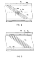
- Fig. 4 generally shows a magnetic tape TP DG composed of the recording format of a digital VTR which can also reproduce the magnetic tape TP AN composed of the conventional analog VTR recording format as shown in Fig. 5.
- the audio recording track TR A1 which is for one channel of the longitudinal audio recording tracks TR A1 and TR A2 which are for two channels in the analog VTR recording format will be removed, and simultaneously the other channel TR A2 will be used as a cue track TR CUE and the length of helical recording track TR DG will be extended for that part.
- the effective track width AR DG of the helical recording track TR DG becomes wider than the effective track width AR AN of the helical recording track TR AN in the analog VTR recording format.
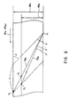
- the drum diameter of the analog VTR is d
- the drum diameter of the digital VTR is d'
- the lead angle ⁇ '' of the digital VTR is 4.607° and is selected almost the same with the lead angle ⁇ ' of the analog VTR 4.6°.
- the same drum it is capable of recording and reproducing the magnetic tape TP DG composed of digital VTR recording format and at the same time it is capable of reproducing the magnetic tape TP AN composed of analog VTR recording format.
- the drum diameter d' of the digital VTR recording format is selected to the value 81.4 [mm] ⁇ considering the length of the helical recording track and synchronization of video signals to be recorded in place of the standard drum diameter 74.487 [mm] ⁇ in the analog VTR recording format and thus an ill effect which may occur by increasing the wrap angle of the magnetic tape for the drum can be prevented in advance.
- the helical recording track will be scanned with the just tracking condition in utilizing a dynamic tracking head for controlling the magnetic head in the direction of width of the helical recording track by the control signal, however, this drum diameter 81.4 [mm] ⁇ is the value selected considering the restoration time of the dynamic tracking head.
- the magnetic recording and/or reproducing apparatus 1 is constituted as shown in Fig. 3 is order to suppress noises in reproducing the magnetic tape TP AN of analog VTR. More specifically, RF signals RF A and RF B (Figs. 7A and 7B) to be reproduced from the magnetic tape TP AN at rotary heads 3A and 3B mounted on a drum 2 will be amplified at reproducing amplifiers 4A and 4B and will be outputted to the first switch circuit 5. Frequency modulated video signals and frequency modulated audio signals are overlap recorded on the magnetic tape TP AN .
- This first switch circuit 5 switches over signals RF A , RF B and combines them corresponding to the switch pulse SW (Fig. 7C) generated at a servo circuit 6 which controls rotation of the drum 2, and the resultant composite RF signal RF AB will be inputted to the second switch circuit 7.
- the second switch circuit 7 selectively outputs the composite RF signal RF AB depending on whether the reproducing magnetic tape TP is the digital VTR recording format or the analog VTR recording format. And in practice, in the case of digital VTR recording format, the composite RE signal RF AB will be supplied to a digital signal reproducing circuit 8, but on the other hand, in the case of analog VTR recording format, the composite RF signal RF AB will be supplied to a high-pass filter (HPF) 9 and a low-pass filter (LPF) 10.
- HPF high-pass filter
- LPF low-pass filter
- This high pass filter 9 extracts video RF signal RF V from the composite RF signal RF AB (Fig. 7D) and this is amplified at an amplifier 11 and simultaneously equalized and frequency characteristic is corrected, then demodulated at demodulator 12.
- the resulting video signal VD as shown in Fig. 7E, wherein the time base is compressed and there exists large FM noise part in addition to the video part. Therefore, the video signal VD is inputted to a time base extension circuit 13 and the time base is extended and video signal VD0 at the time of recording is restored and outputted.
- This time base extension circuit 13 is constituted by the conventional general construction and generates a write in clock at the timing of video signal VD and simultaneously converts the video signal VD from analog to digital corresponding to this clock, and reads out the outputs of this memory at the timing of output clock generated from the correct standard signal and executes digital-to-analog conversion; and thus, the video signal VD (Fig. 7F) can be time base extended.
- the time base extension circuit 13 extends the time base and simultaneously can correct the jitter to be occurred by the speed error of the magnetic tape and the rotary head and others.
- the low pass filter 10 extracts the audio RF signal RF A from the composite RF signal RF AB (Fig. 7G) and this is amplified at an amplifier 14 and demodulated at a demodulator 15. As shown in Fig. 7H, the resulting audio signal AD is time base compressed as same as described above and a large FM noise part exists in addition to the audio part. Therefore, the audio signal AD is inputted to a time base extension circuit 16 and the time base is extended and the audio signal AD0 (Fig. 7I) in recording will be restored and outputted.
- the time base extension circuit 16 converts the audio signal AD to be inputted into digital data in an analog-to-digital converter 20 and write in a memory 21 at the timing of write-in clock WCK from writing clock generating circuit 23 and reads out at the timing of read-out clock RCK from reading clock generating circuit 24.
- the signal read out is converted into digital signal at a digital-to-analog converter 22 and thus audio signal AD0 which is time base extended can be obtained.
- the magnetic recording and/or reproducing apparatus capable of obtaining the reproducing signals to be restored from the recording signals at the time of recording can be realized.
- the vertical synchronizing section of the reproducing video signal VD PB (Fig. 11A) in case of normal reproduction at the analog VTR is shown in Figs. 11A to 11C as an example of the field 1 in the 525/60 system.
- the pulse PWZ (Fig. 11C) synchronized with the horizontal synchronizing signal H SYNC (Fig. 11B) which is called as write zero is used as the timing pulse to write-in the video signal in the memory in the time base corrector.
- the figures show that there are 525 write zero pulses per one full turn of the drum. Since the horizontal synchronizing signal H SYNC does not exist in the equivalent pulse section, it moves freely from “a” to "b” in the figure, from the horizontal synchronizing signal H SYNC of preceding vertical synchronizing signal, and after entering in the new vertical synchronizing period, it synchronizes at the 11th line.
- the sckew occurs at the switching point. However, since the condition does not change if it is within 1/2 H, it is possible to judge whether it is the normal reproduction or not, or to define what numbered line by counting these write zero pulses PWZ and furthermore, it is possible to interpolate in the case where the vertical synchronizing period could not be detected due to the drop out or such.
- the drum diameter of the digital VTR recording format will be selected to the value 81.4 [mm] ⁇ in place of the standard drum diameter 74.487 [mm] ⁇ of the analog VTR recording format by adding the condition to become an integer multiple of the periodic time of horizontal synchronizing signal video signals to be reproduced the periodic time of a full turn of the drum and the condition of the equations (4) to (6) as described above, and thus an ill effect in case of increasing the wrap angle of the magnetic tape for the drum can be evaded in advance.
- the drum diameter d' of the drum whereon the rotary head for recording and reproducing the magnetic tape TP DG of the digital VTR recording format is mounted is set bigger than the standard drum diameter d of the analog VTR recording format, and the periodic time of a full turn is set to become an integer multiple of the periodic time of the horizontal synchronizing signal H SYNC of the video signals VD PB to be reproduced
- a magnetic recording and/or reproducing apparatus capable of at least reproducing the video signals of the magnetic tape TP AN of the analog VTR recording format can be obtained in utilizing the drum for recording and reproducing the video signals on the magnetic tape TP DG of the digital VTR recording format.
- the wrap angle can be selected to various values and thus, the magnetic recording and/or reproducing apparatus capable of loading the magnetic tape with various loading systems can be obtained.
- the embodiment discussed above has dealt with the case of utilizing the write-in and read-out clock signals corresponding to the ratio of drum diameter at the time of recording and at the time of reproducing in order to extend the time base of audio signals.
- the write-in and read-out clock signals may be generated corresponding to the synchronizing signal and standard synchronizing signal contained in video signals since the audio signals are time base compressed in the same manner as the video signals.
- synchronizing signal of the video signal VD is detected at a synchronizing detection circuit 25 and a write-in clock (WCK) generation circuit 23 generates write-in clocks WCK V and WCK A of the video signal VD and audio signal AD corresponding to the synchronizing signal and supplies to memories 27 and 21 respectively.
- WCK write-in clock
- the standard synchronizing signal inputted to a synchronizing detection circuit 29 and a read-out clock (RCK) generation circuit 24 generates read-out clocks RCK V and RCK A of the video signal VD and audio signal AD corresponding to this synchronizing signal and supplies to the memories 27 and 21 respectively, and thus, the audio signal AD and video signal VD will be synchronized and the audio signal AD0 and the video signal VD0 which are more correctly time base extended can be outputted.
Landscapes
- Engineering & Computer Science (AREA)
- Multimedia (AREA)
- Signal Processing (AREA)
- Television Signal Processing For Recording (AREA)
- Recording Or Reproducing By Magnetic Means (AREA)
- Signal Processing For Digital Recording And Reproducing (AREA)
Applications Claiming Priority (4)
| Application Number | Priority Date | Filing Date | Title |
|---|---|---|---|
| JP14657792A JPH05314402A (ja) | 1992-05-12 | 1992-05-12 | 磁気記録再生装置及び磁気記録再生方法 |
| JP146577/92 | 1992-05-12 | ||
| JP146203/92 | 1992-05-13 | ||
| JP14620392A JPH05314439A (ja) | 1992-05-13 | 1992-05-13 | 磁気記録再生装置 |
Publications (2)
| Publication Number | Publication Date |
|---|---|
| EP0570202A1 true EP0570202A1 (de) | 1993-11-18 |
| EP0570202B1 EP0570202B1 (de) | 1998-01-21 |
Family
ID=26477084
Family Applications (1)
| Application Number | Title | Priority Date | Filing Date |
|---|---|---|---|
| EP93303656A Expired - Lifetime EP0570202B1 (de) | 1992-05-12 | 1993-05-12 | Methode und Gerät für magnetische Aufnahme und/oder Wiedergabe |
Country Status (4)
| Country | Link |
|---|---|
| US (1) | US5504632A (de) |
| EP (1) | EP0570202B1 (de) |
| KR (1) | KR100292588B1 (de) |
| DE (1) | DE69316435T2 (de) |
Cited By (3)
| Publication number | Priority date | Publication date | Assignee | Title |
|---|---|---|---|---|
| GB2329510A (en) * | 1997-09-17 | 1999-03-24 | Sony Corp | Differing formats data recording and reproducing |
| EP0989546A3 (de) * | 1998-09-25 | 2000-05-10 | Sony Corporation | Verfahren und Vorrichtung zur magnetischen Aufzeichnung für digitale Signale, Verfahren und Vorrichtung zur Wiedergabe digitaler Signale und bandförmiger Aufzeichnungsträger |
| EP0940804A3 (de) * | 1998-03-02 | 2004-01-28 | Sony Corporation | Digitalsignale-Magnetaufzeichnungsmethode und -gerät, Digitalsignale-Magnetwiedergabemethode und -gerät und bandförmiges Aufzeichnungsmedium |
Families Citing this family (6)
| Publication number | Priority date | Publication date | Assignee | Title |
|---|---|---|---|---|
| JPH08279250A (ja) * | 1995-04-04 | 1996-10-22 | Matsushita Electric Ind Co Ltd | ディジタル信号記録方法とディジタル信号書き換え方法及びfm音声信号/ディジタル信号記録兼用ドラム装置とディジタル信号磁気記録再生装置 |
| JP4055096B2 (ja) * | 1998-12-16 | 2008-03-05 | ソニー株式会社 | 磁気再生装置及び方法 |
| EP1128673A3 (de) * | 2000-02-23 | 2006-05-10 | THOMSON multimedia | Videovorrichtung, insbesondere Videoaufzeichnungsgeräte, und Prozesse zur Verwendung in dieser Vorrichtung |
| US7194195B1 (en) | 2001-07-17 | 2007-03-20 | Advanced Micro Devices, Inc. | Software based digital video recorder device |
| JP4507803B2 (ja) * | 2004-09-30 | 2010-07-21 | ミツミ電機株式会社 | 磁気記録再生装置 |
| JP4353049B2 (ja) * | 2004-09-30 | 2009-10-28 | ミツミ電機株式会社 | 磁気記録再生装置 |
Citations (6)
| Publication number | Priority date | Publication date | Assignee | Title |
|---|---|---|---|---|
| EP0102600A2 (de) * | 1982-08-27 | 1984-03-14 | Hitachi, Ltd. | Verfahren und Anordnung zur magnetischen Aufzeichnung und Wiedergabe |
| US4510538A (en) * | 1981-12-14 | 1985-04-09 | Sony Corporation | Magnetic recording apparatus |
| EP0179920A1 (de) * | 1984-04-18 | 1986-05-07 | Sony Corporation | Vorrichtung zum speichern von datensignalen |
| US4633332A (en) * | 1983-01-11 | 1986-12-30 | Victor Company Of Japan, Limited | Multi-mode magnetic recording system and multi-mode magnetic recording and playback system for VTR |
| EP0211339A2 (de) * | 1985-07-25 | 1987-02-25 | Sony Corporation | Gerät zur Aufnahme oder Wiedergabe mit einer Mehrzahl von Drehköpfen |
| EP0454408A2 (de) * | 1990-04-27 | 1991-10-30 | Matsushita Electric Industrial Co., Ltd. | Gerät zur Aufnahme/Wiedergabe von digitalen Videosignalen |
Family Cites Families (5)
| Publication number | Priority date | Publication date | Assignee | Title |
|---|---|---|---|---|
| US4346397A (en) * | 1978-01-23 | 1982-08-24 | Victor Company Of Japan, Ltd. | Apparatus for reproducing a video signal of one system with conversion to a video signal of another system |
| JP2627498B2 (ja) * | 1986-12-08 | 1997-07-09 | キヤノン株式会社 | 映像信号記録装置 |
| JPH0770152B2 (ja) * | 1989-09-04 | 1995-07-31 | シャープ株式会社 | 回転ヘッド形磁気テープ記録再生装置 |
| CA2030885C (en) * | 1989-11-29 | 2000-11-07 | Yutaka Soda | Analog/digital compatible reproducing system |
| JPH04188979A (ja) * | 1990-11-21 | 1992-07-07 | Sharp Corp | 映像信号記録装置 |
-
1993
- 1993-05-11 KR KR1019930008019A patent/KR100292588B1/ko not_active Expired - Fee Related
- 1993-05-12 EP EP93303656A patent/EP0570202B1/de not_active Expired - Lifetime
- 1993-05-12 DE DE69316435T patent/DE69316435T2/de not_active Expired - Fee Related
-
1995
- 1995-04-04 US US08/416,510 patent/US5504632A/en not_active Expired - Lifetime
Patent Citations (6)
| Publication number | Priority date | Publication date | Assignee | Title |
|---|---|---|---|---|
| US4510538A (en) * | 1981-12-14 | 1985-04-09 | Sony Corporation | Magnetic recording apparatus |
| EP0102600A2 (de) * | 1982-08-27 | 1984-03-14 | Hitachi, Ltd. | Verfahren und Anordnung zur magnetischen Aufzeichnung und Wiedergabe |
| US4633332A (en) * | 1983-01-11 | 1986-12-30 | Victor Company Of Japan, Limited | Multi-mode magnetic recording system and multi-mode magnetic recording and playback system for VTR |
| EP0179920A1 (de) * | 1984-04-18 | 1986-05-07 | Sony Corporation | Vorrichtung zum speichern von datensignalen |
| EP0211339A2 (de) * | 1985-07-25 | 1987-02-25 | Sony Corporation | Gerät zur Aufnahme oder Wiedergabe mit einer Mehrzahl von Drehköpfen |
| EP0454408A2 (de) * | 1990-04-27 | 1991-10-30 | Matsushita Electric Industrial Co., Ltd. | Gerät zur Aufnahme/Wiedergabe von digitalen Videosignalen |
Cited By (6)
| Publication number | Priority date | Publication date | Assignee | Title |
|---|---|---|---|---|
| GB2329510A (en) * | 1997-09-17 | 1999-03-24 | Sony Corp | Differing formats data recording and reproducing |
| GB2329510B (en) * | 1997-09-17 | 1999-12-01 | Sony Corp | Data recording and reproducing |
| US6172829B1 (en) | 1997-09-17 | 2001-01-09 | Sony Corporation | Digital audio tape recording/reproducing apparatus for use with multiple formats |
| EP0940804A3 (de) * | 1998-03-02 | 2004-01-28 | Sony Corporation | Digitalsignale-Magnetaufzeichnungsmethode und -gerät, Digitalsignale-Magnetwiedergabemethode und -gerät und bandförmiges Aufzeichnungsmedium |
| EP0989546A3 (de) * | 1998-09-25 | 2000-05-10 | Sony Corporation | Verfahren und Vorrichtung zur magnetischen Aufzeichnung für digitale Signale, Verfahren und Vorrichtung zur Wiedergabe digitaler Signale und bandförmiger Aufzeichnungsträger |
| US6721487B1 (en) | 1998-09-25 | 2004-04-13 | Sony Corporation | Magnetic recording method and apparatus for digital signals, magnetic reproducing method and apparatus for digital signals and tape-shaped recording medium |
Also Published As
| Publication number | Publication date |
|---|---|
| US5504632A (en) | 1996-04-02 |
| DE69316435D1 (de) | 1998-02-26 |
| KR930023928A (ko) | 1993-12-21 |
| EP0570202B1 (de) | 1998-01-21 |
| KR100292588B1 (ko) | 2001-06-15 |
| DE69316435T2 (de) | 1998-05-14 |
Similar Documents
| Publication | Publication Date | Title |
|---|---|---|
| US4772959A (en) | Digital signal recording and reproducing apparatus | |
| EP0335273B1 (de) | System zum Aufzeichnen und Wiedergeben von digitalen Audiosignalen | |
| EP0570202A1 (de) | Methode und Gerät für magnetische Aufnahme und/oder Wiedergabe | |
| EP0214343B1 (de) | Wiedergabegerät | |
| EP0432539B1 (de) | Phasenregelschaltung | |
| GB2252196A (en) | Video reproducing apparatus | |
| GB2128838A (en) | Digital television signal reproducing methods and apparatus | |
| US4905093A (en) | Video reproduction apparatus with plural heads and field memory | |
| US5684648A (en) | Digital signal recording apparatus with means for detecting an ID signal and controlling the number of signal samples | |
| US5313339A (en) | Apparatus using a rotary head for recording digital video and audio signals at double speed | |
| JP2505470B2 (ja) | 回転ヘッド形磁気記録再生装置 | |
| EP0548359B1 (de) | Digitales signalwiedergabegerät mit variabler geschwindigkeit | |
| KR100294400B1 (ko) | 시간압축된신호를기록및재생하는방법 | |
| JP3123050B2 (ja) | 記録装置 | |
| EP0830022A2 (de) | System zur Änderung der Zeitsteuerung der Wiedergabe aufgenommener Bildsignale | |
| JP3365560B2 (ja) | 磁気再生装置 | |
| JP2703935B2 (ja) | ビデオデータ再生装置 | |
| KR940009171B1 (ko) | 에러플래그신호를 이용한 다이내믹 트래킹장치 및 방식 | |
| JPH05328274A (ja) | 磁気記録再生装置 | |
| JPH05314402A (ja) | 磁気記録再生装置及び磁気記録再生方法 | |
| JPS61104303A (ja) | 磁気記録再生装置 | |
| JPS61104369A (ja) | 磁気記録再生装置 | |
| JPH03230304A (ja) | 磁気記録再生装置 | |
| JPH05314439A (ja) | 磁気記録再生装置 | |
| JPH03145390A (ja) | 映像信号記録再生装置 |
Legal Events
| Date | Code | Title | Description |
|---|---|---|---|
| PUAI | Public reference made under article 153(3) epc to a published international application that has entered the european phase |
Free format text: ORIGINAL CODE: 0009012 |
|
| AK | Designated contracting states |
Kind code of ref document: A1 Designated state(s): DE FR GB |
|
| 17P | Request for examination filed |
Effective date: 19940406 |
|
| 17Q | First examination report despatched |
Effective date: 19960822 |
|
| GRAG | Despatch of communication of intention to grant |
Free format text: ORIGINAL CODE: EPIDOS AGRA |
|
| GRAG | Despatch of communication of intention to grant |
Free format text: ORIGINAL CODE: EPIDOS AGRA |
|
| GRAH | Despatch of communication of intention to grant a patent |
Free format text: ORIGINAL CODE: EPIDOS IGRA |
|
| GRAH | Despatch of communication of intention to grant a patent |
Free format text: ORIGINAL CODE: EPIDOS IGRA |
|
| GRAA | (expected) grant |
Free format text: ORIGINAL CODE: 0009210 |
|
| AK | Designated contracting states |
Kind code of ref document: B1 Designated state(s): DE FR GB |
|
| REF | Corresponds to: |
Ref document number: 69316435 Country of ref document: DE Date of ref document: 19980226 |
|
| ET | Fr: translation filed | ||
| PLBE | No opposition filed within time limit |
Free format text: ORIGINAL CODE: 0009261 |
|
| STAA | Information on the status of an ep patent application or granted ep patent |
Free format text: STATUS: NO OPPOSITION FILED WITHIN TIME LIMIT |
|
| 26N | No opposition filed | ||
| REG | Reference to a national code |
Ref country code: GB Ref legal event code: IF02 |
|
| PGFP | Annual fee paid to national office [announced via postgrant information from national office to epo] |
Ref country code: DE Payment date: 20070510 Year of fee payment: 15 |
|
| PGFP | Annual fee paid to national office [announced via postgrant information from national office to epo] |
Ref country code: GB Payment date: 20070509 Year of fee payment: 15 |
|
| PGFP | Annual fee paid to national office [announced via postgrant information from national office to epo] |
Ref country code: FR Payment date: 20070510 Year of fee payment: 15 |
|
| GBPC | Gb: european patent ceased through non-payment of renewal fee |
Effective date: 20080512 |
|
| REG | Reference to a national code |
Ref country code: FR Ref legal event code: ST Effective date: 20090119 |
|
| PG25 | Lapsed in a contracting state [announced via postgrant information from national office to epo] |
Ref country code: FR Free format text: LAPSE BECAUSE OF NON-PAYMENT OF DUE FEES Effective date: 20080602 Ref country code: DE Free format text: LAPSE BECAUSE OF NON-PAYMENT OF DUE FEES Effective date: 20081202 |
|
| PG25 | Lapsed in a contracting state [announced via postgrant information from national office to epo] |
Ref country code: GB Free format text: LAPSE BECAUSE OF NON-PAYMENT OF DUE FEES Effective date: 20080512 |