EP0570286A2 - Hebevorrichtung mittels eines Kabels für die Handhabung schwerer Lasten im Inneren eines dichten, gepanzerten Gehäuses - Google Patents
Hebevorrichtung mittels eines Kabels für die Handhabung schwerer Lasten im Inneren eines dichten, gepanzerten Gehäuses Download PDFInfo
- Publication number
- EP0570286A2 EP0570286A2 EP93401220A EP93401220A EP0570286A2 EP 0570286 A2 EP0570286 A2 EP 0570286A2 EP 93401220 A EP93401220 A EP 93401220A EP 93401220 A EP93401220 A EP 93401220A EP 0570286 A2 EP0570286 A2 EP 0570286A2
- Authority
- EP
- European Patent Office
- Prior art keywords
- enclosure
- lifting device
- cable
- main arm
- bushing
- Prior art date
- Legal status (The legal status is an assumption and is not a legal conclusion. Google has not performed a legal analysis and makes no representation as to the accuracy of the status listed.)
- Granted
Links
Images

Classifications
-
- B—PERFORMING OPERATIONS; TRANSPORTING
- B66—HOISTING; LIFTING; HAULING
- B66C—CRANES; LOAD-ENGAGING ELEMENTS OR DEVICES FOR CRANES, CAPSTANS, WINCHES, OR TACKLES
- B66C23/00—Cranes comprising essentially a beam, boom, or triangular structure acting as a cantilever and mounted for translatory of swinging movements in vertical or horizontal planes or a combination of such movements, e.g. jib-cranes, derricks, tower cranes
- B66C23/18—Cranes comprising essentially a beam, boom, or triangular structure acting as a cantilever and mounted for translatory of swinging movements in vertical or horizontal planes or a combination of such movements, e.g. jib-cranes, derricks, tower cranes specially adapted for use in particular purposes
- B66C23/20—Cranes comprising essentially a beam, boom, or triangular structure acting as a cantilever and mounted for translatory of swinging movements in vertical or horizontal planes or a combination of such movements, e.g. jib-cranes, derricks, tower cranes specially adapted for use in particular purposes with supporting couples provided by walls of buildings or like structures
- B66C23/22—Window cranes, i.e. adapted to be supported in window openings
-
- B—PERFORMING OPERATIONS; TRANSPORTING
- B25—HAND TOOLS; PORTABLE POWER-DRIVEN TOOLS; MANIPULATORS
- B25J—MANIPULATORS; CHAMBERS PROVIDED WITH MANIPULATION DEVICES
- B25J21/00—Chambers provided with manipulation devices
-
- G—PHYSICS
- G21—NUCLEAR PHYSICS; NUCLEAR ENGINEERING
- G21F—PROTECTION AGAINST X-RADIATION, GAMMA RADIATION, CORPUSCULAR RADIATION OR PARTICLE BOMBARDMENT; TREATING RADIOACTIVELY CONTAMINATED MATERIAL; DECONTAMINATION ARRANGEMENTS THEREFOR
- G21F7/00—Shielded cells or rooms
- G21F7/06—Structural combination with remotely-controlled apparatus, e.g. with manipulators
- G21F7/066—Remotely manipulated tools
Definitions
- the invention relates to the handling of heavy loads placed inside an enclosure inaccessible to operators, such as a box or a sealed cell used in the nuclear environment for the containment of radioactive materials. Inside this type of enclosure, box or watertight cell, handling operations on products, equipment, accessories or materials must be carried out permanently according to operational requirements: research and development of processes, production or simply care and maintenance.
- shields made up of various materials (cast iron, lead, steel, concretes, glasses, etc ). and of variable thicknesses (from a few centimeters to more than a meter), dimensioned on a case by case basis to ensure the protection of operators against the harmful effects of alpha, beta, gamma or neutron radiation.
- telemanipulators are generally used which are mechanical devices passing through the walls of these enclosures, boxes or cells, and the associated radiological protections, in a sealed manner and without generating any leakage. of radiation.
- remote manipulators are often of the master-slave type, i.e. they are controlled by through an operator outside the shielded enclosure.
- the existing manipulators used in this field are complex and relatively fragile devices generally have many degrees of freedom, so as to obtain, for a small load, very high handling precision, comparable to that of the human hand . This precision in movements is obtained at the expense of the load. Thus, only loads of the order of a few kilograms (3 to 25 kg) can be lifted with such remote manipulators. To lift heavier loads placed inside a watertight enclosure, it is mandatory to provide a hoist specially positioned inside the enclosure. This type of hoist is often mounted on an overhead crane or a jib bearing on the structure of the box or cell, which limits with current speakers its capacity to 50 or 100 kg.
- the object of the invention is to remedy this drawback by proposing a lifting device which can be adapted in one of the housings and orifices originally provided for the passages of the biological protection and of the sealed enclosure by the remote manipulators such that they have been described above, or possibly in a reservation of the same type provided for this purpose, at the design of the cell.
- the device comprises a crossing sleeve in which the horizontal support structure is slidably mounted and whose external shape corresponds with the internal shape of an existing hole in a shielding of the enclosure usually intended to receive another device. , such as a remote manipulator or planned from the design of the enclosure for this use.
- This control system is preferably made up of two connecting rods mounted in the main arm, parallel and along the main arm to form a deformable parallelogram, a first end of each connecting rod being hinged on the first end of the hinged beam on the side and else of the vertical pivot axis, a second end being mounted to the control system.
- the horizontal support structure is slidably mounted by means of guide rollers mounted freely in rotation in the bushing at the periphery of the main arm.
- the preferred embodiment of the motor means causes them to act on the cable by means of a dynamometric axis to read the weight of the load on the cable.
- the control system preferably comprises a screw / nut system for blocking the longitudinal movement of the horizontal support structure.
- the invention is particularly applicable to sealed enclosures and is equipped in this case with a sealing system with an ejectable ring.
- Figure 1 shows the lifting device according to the invention 7 placed to be operational inside a sealed metal enclosure 2.
- the latter is placed inside a shield 1.
- the assembly constitutes a sealed enclosure shielded for handling charges 6 under gamma radiation.
- Shield 1 has a frame 5 inside which is placed a viewing window 3 for operators located outside the enclosure 2. This frame also has a through hole 4 for the device according to the invention 7 and for other devices, such as remote manipulators.
- the lifting device according to the invention 7 is therefore intended to be placed inside the hole 4 of the wall frame 5 in place of a remote manipulator previously located there and being operational inside the sealed enclosure. 2 or in an identical hole provided for this purpose in the design of the enclosure.
- the lifting device according to the invention 7 must have a cross section corresponding to the internal shape of the hole 4 of the wall frame 5. This section is generally round.
- the remote manipulators used inside such enclosures are surrounded by an elastic protective sleeve 9.
- the sleeve 9 remains inside the sealed enclosure 2.
- the lifting device according to the invention 7 it is fitted with a new protective sleeve 9 and a sealing system on an ejectable ring. This positioning causes the old protective sleeve 9 which falls into the enclosure 2 to be released.
- this system comprises for example a support ring, an enclosure ring, an immobilization ring and a lip seal.
- the lifting device according to the invention must have inside it several degrees of freedom at the end of its cable 100, and in particular to its gripping hook 8. Means are therefore provided for horizontally sliding the device 7 through the enclosure 2 and the shielding 1 and preferably for pivoting the gripping hook 8 of the cable 100 around 'a vertical pivot axis 10.
- this horizontal carrying structure comprises a bushing 13 in which it is mounted sliding. This bushing 13 is fixed to the wall frame 5 of the shield 1. The horizontal support structure can therefore slide horizontally inside the sealed enclosure 2.
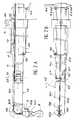
- FIGS. 2A and 2B The preferred construction of the lifting device according to the invention is detailed in FIGS. 2A and 2B.
- FIG. 2A we find certain elements already mentioned, such as the gripping hook 8, the cable 100, the pulley 99 mounted to rotate about a horizontal axis, the wall frame 5 and the sleeve 13.
- the wall frame 5 having a hole 4 of determined diameter and corresponding to the devices previously installed, namely a conventional remote manipulator, the bushing 13 has an external diameter corresponding to this diameter, so that it can be housed and fixed there tightly .
- a lifting ring 60 can complete this flange 15 to facilitate transport and handling of the lifting device, during its introduction and extraction, for example by means of a bridge.
- the horizontal support structure mainly comprises a main arm 11 slidingly mounted inside the bushing 13 and an articulated beam 12.
- the latter is pivotally mounted by a first end 12A around a vertical axis 10 at a first end 11A of the main arm 11.
- the first end 11A of the main arm is machined in the form of a female yoke thus receiving the first end 12A of the articulated beam machined in a male yoke.
- the pulley 99 describes an arc of a circle around the vertical axis 10 when the articulated beam 12 pivots.
- the gripping hook 8 therefore also describes this circular arc. It is thus possible for the latter to sweep the greater part of the surface on the ground of the sealed enclosure, thanks to the combination of this pivoting movement around the vertical axis 10 and the horizontal translational movement in the sheath crossing 13 along the horizontal axis 20.
- the pulley 99 is in fact mounted at the second end 12B of the articulated beam 12.
- the cable 100 is placed in the articulated beam 12, inside a groove 12C and in the main arm 11, inside a groove 11C.
- a first fastening piece 98 is placed at the second end 12B of the articulated beam 12 to hold the cable 100 in the groove of the pulley 99, whatever the movements of the articulated beam 12 and the loads suspended on the cable 100.
- two guide pulleys 22 are fixed on the first end 11A of the main arm 11 at the level of the vertical pivot axis 10.
- the sliding movement of the main arm 11 in the bushing 13 can be achieved by means of several rollers 96 mounted at each end of the bushing 13. These rollers therefore have axes of rotation orthogonal to the horizontal sliding axis 20 It is thus possible to provide six rollers 96 at each end of the bushing 13.
- the main arm 11 has bearing surfaces on which the rollers 96 can roll. So that the articulated beam 13 can pivot, it is necessary to use transmission elements of the control system, since this articulated beam 13 is located inside the sealed enclosure while the possible operator is outside.
- a particular embodiment of these transmission elements can consist mainly of two connecting rods 23 arranged longitudinally inside the main arm 11, parallel to each other. One of their first ends 57 is pivotally mounted at the first end 12A of the articulated beam 12, on either side of the pivot axis 10. A second end 63 is mounted at a control system 62.
- the control system 62 of the connecting rods 23 is shown diagrammatically by two handles 64 making it possible to translate the two connecting rods 23 in two opposite directions.
- the two connecting rods 23 thus form with the first end 12A of the articulated beam 12 and the control system 62 a deformable parallelogram.
- the gripping hook 8 is secured to the cable 100 by means of a pin 111 to a base 109 fixed to the protective sleeve 9.
- the gripping hook 8 and the base 109 pivot in a position close to the horizontal remaining inscribed in the external shape of the horizontal support structure, thus allowing the introduction of the lifting device according to the invention inside the enclosure through the hole 4 of the wall frame 5 .
- the known device for ensuring sealing is a sealing system with an ejectable ring. In this type of system, all the elements ensuring the tightness of the previously installed device are therefore released inside the sealed enclosure, pushed by the same sealing elements of the new instrument to be placed in place of the 'former.
- the first motor means making it possible to pull or let the cable descend are shown diagrammatically by the crank 113. It is also possible to use a motorized winch as well as a system of screw / gear reduction. It is also possible to use a dynamometric axis 112 around which the cable 100 passes to allow the reading of the weight of the load suspended from the cable 100. This dynamometric axis 112 also makes it possible to safely stop the motorization of the cable 100 opposite of a determined maximum load.
- a screw / nut system shown diagrammatically by the handle 65 makes it possible to block the main arm 11 inside the bushing 13 to block the entire horizontal support structure in a determined longitudinal position.
- the preferred shape of the bushing 11 is circular. It is reported that it is in any case composed of a tube whose external profile is in conformity with that of the through holes 4 of the wall frames 5 of standard remote manipulators.
- the range of the bushing 13 on the main arm 11 has a determined length sufficient to allow the handling of heavy loads at the end of the horizontal support structure.
- control members can be different.
- the connecting rods 23 can be replaced by a closed loop consisting of a chain or a belt and a sprocket. It is thus possible to obtain a greater pivoting of the articulated beam.
- the cable 100 can be replaced by a ribbon chain allowing a spiral winding.
- the locking screw / nut system 65 can be replaced by a pinion / rack system.
- This device makes it possible to handle high loads, which can reach several hundreds of kilograms, without influencing the structure of the containment since the reaction forces applied to the device are entirely taken up by the structure of the shielding or wall. surrounding the sealed enclosure.
- a special lifting device for temporarily carrying out lifting and moving operations of heavy loads inside the enclosure. waterproof.
Landscapes
- Engineering & Computer Science (AREA)
- Mechanical Engineering (AREA)
- Civil Engineering (AREA)
- Structural Engineering (AREA)
- Robotics (AREA)
- Physics & Mathematics (AREA)
- General Engineering & Computer Science (AREA)
- High Energy & Nuclear Physics (AREA)
- Manipulator (AREA)
- Load-Engaging Elements For Cranes (AREA)
Applications Claiming Priority (2)
| Application Number | Priority Date | Filing Date | Title |
|---|---|---|---|
| FR9205942A FR2691140B1 (fr) | 1992-05-15 | 1992-05-15 | Dispositif de levage par cable pour manipuler des charges lourdes a l'interieur d'une enceinte etanche blindee. |
| FR9205942 | 1992-05-15 |
Publications (3)
| Publication Number | Publication Date |
|---|---|
| EP0570286A2 true EP0570286A2 (de) | 1993-11-18 |
| EP0570286A3 EP0570286A3 (de) | 1994-02-23 |
| EP0570286B1 EP0570286B1 (de) | 1998-09-30 |
Family
ID=9429838
Family Applications (1)
| Application Number | Title | Priority Date | Filing Date |
|---|---|---|---|
| EP93401220A Expired - Lifetime EP0570286B1 (de) | 1992-05-15 | 1993-05-13 | Hebevorrichtung mittels eines Kabels für die Handhabung schwerer Lasten im Inneren eines dichten, gepanzerten Gehäuses |
Country Status (5)
| Country | Link |
|---|---|
| US (1) | US5482169A (de) |
| EP (1) | EP0570286B1 (de) |
| JP (1) | JPH068188A (de) |
| DE (1) | DE69321288T2 (de) |
| FR (1) | FR2691140B1 (de) |
Cited By (3)
| Publication number | Priority date | Publication date | Assignee | Title |
|---|---|---|---|---|
| FR2828126A1 (fr) * | 2001-07-31 | 2003-02-07 | Calhene | Telemanipulateur mecanique protege contre les surcharges |
| CN106315444A (zh) * | 2016-08-11 | 2017-01-11 | 辽宁工程技术大学 | 一种用于深孔剪切波速测试的升降装置 |
| EP3361151A1 (de) * | 2017-01-25 | 2018-08-15 | Clevatech Ltd | An einem abzug montierte winde |
Families Citing this family (6)
| Publication number | Priority date | Publication date | Assignee | Title |
|---|---|---|---|---|
| GB2311955B (en) * | 1996-04-12 | 2000-02-16 | Par Systems Inc | System for performing work in a hot cell |
| DE10116245A1 (de) * | 2001-03-28 | 2002-10-17 | Atecs Mannesmann Ag | Teleskopausleger für einen Fahrzeugkran |
| US9056748B2 (en) | 2011-10-12 | 2015-06-16 | Richard L. Sears | Lifting system and method |
| GB2605331B (en) * | 2017-01-25 | 2022-12-21 | Clevatech Ltd | Flue mounted hoist |
| CN110329924B (zh) * | 2019-08-15 | 2020-02-18 | 常州机电职业技术学院 | 空调室外机吊装装置 |
| WO2024246775A1 (en) * | 2023-05-29 | 2024-12-05 | Atkinsréalis Uk Limited | System and methods for deploying end effector of a collaborative robot in a glovebox |
Family Cites Families (18)
| Publication number | Priority date | Publication date | Assignee | Title |
|---|---|---|---|---|
| DE370575C (de) * | 1923-03-05 | Tech Ges M B H | Lade- und Entladevorrichtung fuer Gueterwagen und Gueterschuppen | |
| GB954014A (en) * | 1960-01-15 | 1964-04-02 | Pye Ltd | Master and slave arm manipulating apparatus |
| US3164267A (en) * | 1961-03-27 | 1965-01-05 | Figure | |
| US3272347A (en) * | 1963-01-14 | 1966-09-13 | Jerome H Lemelson | Article manipulation apparatus |
| FR1406473A (fr) * | 1963-10-21 | 1965-07-23 | Commissariat Energie Atomique | Procédé de reproduction à distance de mouvements de rotation et appareil faisant application dudit procédé ou d'un procédé analogue |
| FR1414864A (fr) * | 1964-09-01 | 1965-10-22 | Commissariat Energie Atomique | Dispositif de manutention pour installation de rechargement en éléments combustibles de réacteur nucléaire |
| FR1460907A (fr) * | 1965-10-22 | 1966-03-04 | Commissariat Energie Atomique | Mécanisme de commande de position des barres de sécurité ou de contrôle d'un réacteur nucléaire |
| US3425569A (en) * | 1966-10-28 | 1969-02-04 | Central Research Lab Inc | Extended reach sealed manipulator |
| FR2038857A5 (de) * | 1969-03-31 | 1971-01-08 | Commissariat Energie Atomique | |
| DE2407228A1 (de) * | 1974-02-15 | 1975-08-28 | Krupp Gmbh | Einrichtung zum umsetzen von brennelementen und regelstaeben in einem kernreaktor |
| FR2287750A1 (fr) * | 1974-10-08 | 1976-05-07 | Commissariat Energie Atomique | Dispositif de surveillance pour barre de controle de reacteur nucleaire |
| FR2570314B1 (fr) * | 1984-09-20 | 1987-03-06 | Commissariat Energie Atomique | Robot porte-outil pour effectuer des interventions a l'interieur d'une enceinte possedant une ouverture d'acces |
| US4822238A (en) * | 1986-06-19 | 1989-04-18 | Westinghouse Electric Corp. | Robotic arm |
| FR2610562B1 (fr) * | 1987-02-05 | 1993-12-03 | Euritech | Pince d'intervention articulee a cinq degres de liberte |
| US4904141A (en) * | 1987-10-28 | 1990-02-27 | Mdc Vacuum Products Corporation | Manipulating device for high vacuum chamber |
| US4858890A (en) * | 1988-02-26 | 1989-08-22 | Brand Scaffold Services, Ltd. | Method and apparatus for lifting objects inside a limited access vessel |
| GB8921832D0 (en) * | 1989-09-27 | 1989-11-08 | Atomic Energy Authority Uk | Manipulator gaiter system |
| FR2658947B1 (fr) * | 1990-02-28 | 1992-05-22 | Cogema | Enceinte mobile d'intervention permettant d'acceder a une installation placee dans une cellule active. |
-
1992
- 1992-05-15 FR FR9205942A patent/FR2691140B1/fr not_active Expired - Fee Related
-
1993
- 1993-05-13 EP EP93401220A patent/EP0570286B1/de not_active Expired - Lifetime
- 1993-05-13 DE DE69321288T patent/DE69321288T2/de not_active Expired - Fee Related
- 1993-05-14 JP JP5113228A patent/JPH068188A/ja active Pending
-
1995
- 1995-01-03 US US08/368,052 patent/US5482169A/en not_active Expired - Fee Related
Cited By (5)
| Publication number | Priority date | Publication date | Assignee | Title |
|---|---|---|---|---|
| FR2828126A1 (fr) * | 2001-07-31 | 2003-02-07 | Calhene | Telemanipulateur mecanique protege contre les surcharges |
| CN106315444A (zh) * | 2016-08-11 | 2017-01-11 | 辽宁工程技术大学 | 一种用于深孔剪切波速测试的升降装置 |
| EP3361151A1 (de) * | 2017-01-25 | 2018-08-15 | Clevatech Ltd | An einem abzug montierte winde |
| US10676323B2 (en) | 2017-01-25 | 2020-06-09 | Clevatech Ltd | Flue mounted hoist |
| GB2560433B (en) * | 2017-01-25 | 2022-09-21 | Clevatech Ltd | Flue mounted hoist |
Also Published As
| Publication number | Publication date |
|---|---|
| DE69321288D1 (de) | 1998-11-05 |
| EP0570286B1 (de) | 1998-09-30 |
| EP0570286A3 (de) | 1994-02-23 |
| FR2691140B1 (fr) | 1998-03-06 |
| FR2691140A1 (fr) | 1993-11-19 |
| JPH068188A (ja) | 1994-01-18 |
| DE69321288T2 (de) | 1999-05-06 |
| US5482169A (en) | 1996-01-09 |
Similar Documents
| Publication | Publication Date | Title |
|---|---|---|
| EP0570286B1 (de) | Hebevorrichtung mittels eines Kabels für die Handhabung schwerer Lasten im Inneren eines dichten, gepanzerten Gehäuses | |
| EP0050561B1 (de) | Verfahrbarer, fernbedienter Manipulator, welcher aus einer luftdichten Zelle zurückziehbar ist | |
| EP0392926B1 (de) | Telemanipulator, vorgesehen zum Aufhängen an einem Hebezeug | |
| EP0451061B1 (de) | Fernbetätigte, motorgetriebene Lastgreifeinrichtung | |
| EP2617040B1 (de) | Vorrichtung zur trockenhandhabung von kernbrennstabbündeln | |
| EP0230593B1 (de) | Automatisierte Anlage zum Ausmauern der Innenwand eines Gefässes | |
| BE897468A (fr) | Procede de remplacement des broches de guidage d'un tube-guide et dispositif correspondant | |
| EP0388296A1 (de) | Interventionsvorrichtung, insbesondere zur Prüfung, Inspektion und Wartung von Wärmeaustauschern | |
| EP0742562B1 (de) | Verfahren zum Einbauen einer abgedichteten Durchführung durch eine Zellenwand | |
| EP0052570B1 (de) | Vorrichtung zum Prüfen des Inneren eines Kernreaktor-Druckgefässes | |
| EP0044246A2 (de) | Bestrahlungsanlage mit einer Vorrichtung zum Einbringen und Positionieren zum Bestrahlen von Targets | |
| EP0077245B1 (de) | Manipulator zum fernbedienbaren Eingreifen im Wasserbehälter eines Dampferzeugers | |
| FR3007883A1 (fr) | Installation et procede de manutention et decoupe de caisson contenant des produits radioactifs | |
| EP0666447B1 (de) | Beweglicher Träger zur Aufnahme von Modulen in einem Schacht, wie einem Auflösebecken | |
| EP0611194B1 (de) | System- und Verfahren zum eingreifen in ein Abdichtungsfenster innerhalb einer Öffnung einer Einschlusszelle | |
| EP0402231A1 (de) | Fernbediente selbstklemmende Greifvorrichtung für zylindrische Fässer | |
| CH507570A (fr) | Bras de manutention | |
| FR2743444A1 (fr) | Procede de visualisation et d'identification sous l'eau d'assemblage de combustible nucleaire et installations le mettant en oeuvre | |
| FR2555796A1 (fr) | Reacteur surregenerateur rapide a refroidissement par metal liquide | |
| FR2583205A1 (fr) | Machine pour demonter des reacteurs nucleaires declasses ou leurs composants | |
| EP0301146A1 (de) | Orientierbare Leuchtvorrichtung für ein radioaktives Material enthaltenden Wassertank | |
| FR2871956A1 (fr) | Installation de connexion electrique a grand nombre de contacts, telemanipulable en milieux extremes | |
| EP0247937A1 (de) | Ladeeinrichtung für spaltzonenbildende Elemente eines Kernreaktors mit schnellen Neutronen | |
| FR2813597A1 (fr) | Dispositif d'installation de longues pieces cylindriques dans une tranchee etroite | |
| EP0218485B1 (de) | Handhabungseinrichtung zum Einführen und Herausziehen einer Apparatur durch eine Öffnung in einem dichten Gehäuse |
Legal Events
| Date | Code | Title | Description |
|---|---|---|---|
| PUAI | Public reference made under article 153(3) epc to a published international application that has entered the european phase |
Free format text: ORIGINAL CODE: 0009012 |
|
| AK | Designated contracting states |
Kind code of ref document: A2 Designated state(s): BE DE GB SE |
|
| PUAL | Search report despatched |
Free format text: ORIGINAL CODE: 0009013 |
|
| AK | Designated contracting states |
Kind code of ref document: A3 Designated state(s): BE DE GB SE |
|
| 17P | Request for examination filed |
Effective date: 19940729 |
|
| 17Q | First examination report despatched |
Effective date: 19970226 |
|
| GRAG | Despatch of communication of intention to grant |
Free format text: ORIGINAL CODE: EPIDOS AGRA |
|
| GRAG | Despatch of communication of intention to grant |
Free format text: ORIGINAL CODE: EPIDOS AGRA |
|
| GRAH | Despatch of communication of intention to grant a patent |
Free format text: ORIGINAL CODE: EPIDOS IGRA |
|
| GRAH | Despatch of communication of intention to grant a patent |
Free format text: ORIGINAL CODE: EPIDOS IGRA |
|
| GRAA | (expected) grant |
Free format text: ORIGINAL CODE: 0009210 |
|
| AK | Designated contracting states |
Kind code of ref document: B1 Designated state(s): BE DE GB SE |
|
| REF | Corresponds to: |
Ref document number: 69321288 Country of ref document: DE Date of ref document: 19981105 |
|
| GBT | Gb: translation of ep patent filed (gb section 77(6)(a)/1977) |
Effective date: 19981203 |
|
| PG25 | Lapsed in a contracting state [announced via postgrant information from national office to epo] |
Ref country code: SE Free format text: LAPSE BECAUSE OF FAILURE TO SUBMIT A TRANSLATION OF THE DESCRIPTION OR TO PAY THE FEE WITHIN THE PRESCRIBED TIME-LIMIT Effective date: 19981231 |
|
| PGFP | Annual fee paid to national office [announced via postgrant information from national office to epo] |
Ref country code: SE Payment date: 19990428 Year of fee payment: 7 |
|
| PGFP | Annual fee paid to national office [announced via postgrant information from national office to epo] |
Ref country code: BE Payment date: 19990430 Year of fee payment: 7 |
|
| PGFP | Annual fee paid to national office [announced via postgrant information from national office to epo] |
Ref country code: GB Payment date: 19990506 Year of fee payment: 7 |
|
| PGFP | Annual fee paid to national office [announced via postgrant information from national office to epo] |
Ref country code: DE Payment date: 19990616 Year of fee payment: 7 |
|
| PLBE | No opposition filed within time limit |
Free format text: ORIGINAL CODE: 0009261 |
|
| STAA | Information on the status of an ep patent application or granted ep patent |
Free format text: STATUS: NO OPPOSITION FILED WITHIN TIME LIMIT |
|
| 26N | No opposition filed | ||
| PG25 | Lapsed in a contracting state [announced via postgrant information from national office to epo] |
Ref country code: GB Free format text: LAPSE BECAUSE OF NON-PAYMENT OF DUE FEES Effective date: 20000513 |
|
| PG25 | Lapsed in a contracting state [announced via postgrant information from national office to epo] |
Ref country code: BE Free format text: LAPSE BECAUSE OF NON-PAYMENT OF DUE FEES Effective date: 20000531 |
|
| BERE | Be: lapsed |
Owner name: COMMISSARIAT A L'ENERGIE ATOMIQUE Effective date: 20000531 |
|
| GBPC | Gb: european patent ceased through non-payment of renewal fee |
Effective date: 20000513 |
|
| EUG | Se: european patent has lapsed |
Ref document number: 93401220.4 |
|
| PG25 | Lapsed in a contracting state [announced via postgrant information from national office to epo] |
Ref country code: DE Free format text: LAPSE BECAUSE OF NON-PAYMENT OF DUE FEES Effective date: 20010301 |