EP0570852A1 - Support intermédiaire amélioré d'un relais pour utilisation, particulièrement aux véhicules automobiles - Google Patents
Support intermédiaire amélioré d'un relais pour utilisation, particulièrement aux véhicules automobiles Download PDFInfo
- Publication number
- EP0570852A1 EP0570852A1 EP19930107834 EP93107834A EP0570852A1 EP 0570852 A1 EP0570852 A1 EP 0570852A1 EP 19930107834 EP19930107834 EP 19930107834 EP 93107834 A EP93107834 A EP 93107834A EP 0570852 A1 EP0570852 A1 EP 0570852A1
- Authority
- EP
- European Patent Office
- Prior art keywords
- foil
- relay
- armature
- movable
- flexion
- Prior art date
- Legal status (The legal status is an assumption and is not a legal conclusion. Google has not performed a legal analysis and makes no representation as to the accuracy of the status listed.)
- Granted
Links
Images


Classifications
-
- H—ELECTRICITY
- H01—ELECTRIC ELEMENTS
- H01H—ELECTRIC SWITCHES; RELAYS; SELECTORS; EMERGENCY PROTECTIVE DEVICES
- H01H50/00—Details of electromagnetic relays
- H01H50/16—Magnetic circuit arrangements
- H01H50/18—Movable parts of magnetic circuits, e.g. armature
- H01H50/30—Mechanical arrangements for preventing or damping vibration or shock, e.g. by balancing of armature
- H01H50/305—Mechanical arrangements for preventing or damping vibration or shock, e.g. by balancing of armature damping vibration due to functional movement of armature
-
- H—ELECTRICITY
- H01—ELECTRIC ELEMENTS
- H01H—ELECTRIC SWITCHES; RELAYS; SELECTORS; EMERGENCY PROTECTIVE DEVICES
- H01H50/00—Details of electromagnetic relays
- H01H50/54—Contact arrangements
- H01H50/546—Contact arrangements for contactors having bridging contacts
-
- H—ELECTRICITY
- H01—ELECTRIC ELEMENTS
- H01H—ELECTRIC SWITCHES; RELAYS; SELECTORS; EMERGENCY PROTECTIVE DEVICES
- H01H50/00—Details of electromagnetic relays
- H01H50/54—Contact arrangements
- H01H50/60—Contact arrangements moving contact being rigidly combined with movable part of magnetic circuit
Definitions
- the invention concerns a relay for use particularly in motor-vehicles, comprising a stable ferromagnetic core, an excitation coil wound around said core, a movable assembly composed from at least one movable ferromagnetic armature, a flexion foil fixed in a determined point of said movable armature and an exchange contact, said relay also includes a return spring to maintain in a position of maximum air gap such armature with respect to said core when the device is in a release condition and at least one closure and/or opening contact that is activated by the movable armature, through its exchange contact, when this is drawn or released by the core.
- Such relays have the drawback that, particularly in certain applications, such as capacitive charges, the wear of the contacts is relatively high, which causes the useful life of the relay to be relatively short; the problem is increased by the mechanical working tolerances that determine a spread of the pressure characteristics with which the contacts become closed.
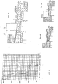
- Another drawback concerns the way with which the flexion foil is united with the movable armature. As shown in figure 1 this is normally united through riveting, that creates only one binding point. This generates an imperfect joint that produces inconstancies on the real value of geometry in play.
- the aim of the present invention is that of eliminating the drawbacks of the known art and in particular to indicate an improved relay that has a wear of the contacts being lesser than that of the traditional relays and therefore a longer useful life.
- the invention has as its object a relay for use particularly in motor-vehicles, comprising a stable ferromagnetic core, an excitation coil wound around said core, a movable assembly constituted of at least one movable ferromagnetic armature, a flexion foil fixed in a determined point of said movable armature and an exchange contact , said relay also includes a return spring to maintain in a position of maximum air gap such armature with respect to said core when the device is in a release condition and at least one closure and/or opening contact that is activated by the movable armature, through its exchange contact, when this is drawn or released by the core, characterised in that it has an intermediate support element for said flexion foil obtained on one of the elements of the movable assembly, and that said support (9) is of such a height and is to be found at a distance from the fixing point (5) so as to produce a sensitive pre-charge of said foil (4), even before the closure.
- All such relays have substantially a structure having a ferromagnetic core, an excitation coil and at least one movable armature.
- figure 1 a traditional relay of the used type in motor vehicles is schematically represented.
- the reference number 1 indicates a stable ferromagnetic core; the reference number 2 indicates an excitation coil wound around said core; the reference number 3 indicates a movable ferromagnetic armature; the reference number 4 indicates a flexion foil, for example being of an approximate triangular form, fixed in a determined point of said movable armature, indicated in turn with the reference number 5; the reference number 6 indicates an electric exchange contact; the reference number 7 indicates a return spring for maintaining such armature in a position of maximum air gap with respects said core when the device is in a rest condition; finally the reference number 8a indicates an electric opening contact and the reference number 8c indicates an electric closure contact that are activated by the movable armature 3, through its exchange contact 6, when this is respectively released or drawn by the core 1.
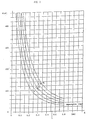
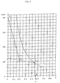
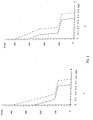
- the corresponding reaction of the mechanical system can be represented, for traditional relays, being on the same previously indicated Cartesian plane, with a segmented line formed from three segments, as represented in figure 3.
- the corresponding reaction of the mechanical system is the result of the combination of the return force of the spring 7 and of the deformation force of the foil 4 that varies depending on the position of the movable assembly as will be clearly seen in the following.
- the segmented line represented in figure 3, is the simple result of the analysis of an extremely simple mechanical model, formed by a movable assembly hinged to an extremity, subjected in the central part to the action of a force and stopped in movement by the appropriately positioned support points.
- the elastic deformation of the foil 4 during the additional movement determines the closure force of the contacts and as a result determines their capacity in supplying current, in point E the armature has carried-out its complete movement and the foil is retracted respects the former, after having rested on the contact 8c.
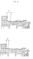
- the movable armature 3 is furnished, at its extremity, with a relief 9 (fig. 5), obtained making an indentation on such armature; due to the effect of such relief 9, the foil 4 results in being furnished with an intermediate point of support appropriately positioned, situated for example approximately midway respect its length.
- Such relief 9 will be advantageously positioned, if compared to the work length of the foil 4, or appropriately dimensioned concerning the height, in a such a way to confer to the gradient of the exercised force on the contact, immediately after its closure, the suitable value according to the type of use of the relay.
- the foil 4 is fixed, through a small fixation plate 5, that transversely extends to the foil 4 for all its width thus realising a perfect joint condition.
- a hole (10) is provided in the flexion foil 4 so as to allow access to the movable armature of a measuring element of the functional characteristics.
- the third segment (C-D) is of a relatively high slope (due to the reduced flexion length L2), while the fourth segment (D-E) is of a minor slope (due to the flexion length L1 + L2).
Landscapes
- Physics & Mathematics (AREA)
- Electromagnetism (AREA)
- Electromagnets (AREA)
- Motor Or Generator Frames (AREA)
- Lock And Its Accessories (AREA)
- Electric Propulsion And Braking For Vehicles (AREA)
- Motorcycle And Bicycle Frame (AREA)
Applications Claiming Priority (2)
| Application Number | Priority Date | Filing Date | Title |
|---|---|---|---|
| ITTO920434 | 1992-05-20 | ||
| ITTO920434A IT1257428B (it) | 1992-05-20 | 1992-05-20 | Rele' perfezionato ad appoggio intermedio per l'impiego particolarmente in autoveicoli |
Publications (2)
| Publication Number | Publication Date |
|---|---|
| EP0570852A1 true EP0570852A1 (fr) | 1993-11-24 |
| EP0570852B1 EP0570852B1 (fr) | 1997-08-27 |
Family
ID=11410475
Family Applications (1)
| Application Number | Title | Priority Date | Filing Date |
|---|---|---|---|
| EP93107834A Revoked EP0570852B1 (fr) | 1992-05-20 | 1993-05-13 | Support intermédiaire amélioré d'un relais pour utilisation, particulièrement aux véhicules automobiles |
Country Status (6)
| Country | Link |
|---|---|
| US (1) | US5329265A (fr) |
| EP (1) | EP0570852B1 (fr) |
| AT (1) | ATE157479T1 (fr) |
| DE (1) | DE69313348T2 (fr) |
| ES (1) | ES2108162T3 (fr) |
| IT (1) | IT1257428B (fr) |
Cited By (1)
| Publication number | Priority date | Publication date | Assignee | Title |
|---|---|---|---|---|
| FR2926665A1 (fr) * | 2008-01-23 | 2009-07-24 | Cartier Technologies Soc Par A | Relais electromecanique a vibrations amorties, et application aux boitiers de commande de chauffage electrique |
Families Citing this family (5)
| Publication number | Priority date | Publication date | Assignee | Title |
|---|---|---|---|---|
| IT1268008B1 (it) * | 1994-02-04 | 1997-02-20 | Bitron A Spa | Relais perfezionato con ancora mobile ad effetto smorzante. |
| DE10162585C1 (de) * | 2001-12-19 | 2003-04-24 | Gruner Ag | Prellreduziertes Relais |
| US8373524B1 (en) * | 2012-02-04 | 2013-02-12 | Nilo Villarin | Relay contacts cross connect mitigation |
| DE102015201703A1 (de) * | 2015-01-30 | 2016-08-04 | Te Connectivity Germany Gmbh | Geräuscharm schaltende elektrische Schaltvorrichtung |
| CN109817492A (zh) * | 2019-02-15 | 2019-05-28 | 厦门城市职业学院(厦门市广播电视大学) | 一种减小触点弹跳的继电器 |
Citations (2)
| Publication number | Priority date | Publication date | Assignee | Title |
|---|---|---|---|---|
| EP0326116A1 (fr) * | 1988-01-29 | 1989-08-02 | Siemens Aktiengesellschaft | Disposition de contacts pour un relais |
| EP0484592A2 (fr) * | 1990-11-09 | 1992-05-13 | Siemens Aktiengesellschaft | Relais électromagnetique avec lame de contact mis sur l'armature |
-
1992
- 1992-05-20 IT ITTO920434A patent/IT1257428B/it active IP Right Grant
-
1993
- 1993-03-31 US US08/040,489 patent/US5329265A/en not_active Expired - Fee Related
- 1993-05-13 DE DE69313348T patent/DE69313348T2/de not_active Revoked
- 1993-05-13 ES ES93107834T patent/ES2108162T3/es not_active Expired - Lifetime
- 1993-05-13 EP EP93107834A patent/EP0570852B1/fr not_active Revoked
- 1993-05-13 AT AT93107834T patent/ATE157479T1/de active
Patent Citations (2)
| Publication number | Priority date | Publication date | Assignee | Title |
|---|---|---|---|---|
| EP0326116A1 (fr) * | 1988-01-29 | 1989-08-02 | Siemens Aktiengesellschaft | Disposition de contacts pour un relais |
| EP0484592A2 (fr) * | 1990-11-09 | 1992-05-13 | Siemens Aktiengesellschaft | Relais électromagnetique avec lame de contact mis sur l'armature |
Cited By (1)
| Publication number | Priority date | Publication date | Assignee | Title |
|---|---|---|---|---|
| FR2926665A1 (fr) * | 2008-01-23 | 2009-07-24 | Cartier Technologies Soc Par A | Relais electromecanique a vibrations amorties, et application aux boitiers de commande de chauffage electrique |
Also Published As
| Publication number | Publication date |
|---|---|
| DE69313348T2 (de) | 1998-03-19 |
| IT1257428B (it) | 1996-01-16 |
| ES2108162T3 (es) | 1997-12-16 |
| ITTO920434A1 (it) | 1993-11-20 |
| US5329265A (en) | 1994-07-12 |
| DE69313348D1 (de) | 1997-10-02 |
| ATE157479T1 (de) | 1997-09-15 |
| EP0570852B1 (fr) | 1997-08-27 |
| ITTO920434A0 (it) | 1992-05-20 |
Similar Documents
| Publication | Publication Date | Title |
|---|---|---|
| US4939492A (en) | Electromagnetic trip device with tripping threshold adjustment | |
| EP0570852B1 (fr) | Support intermédiaire amélioré d'un relais pour utilisation, particulièrement aux véhicules automobiles | |
| US3553729A (en) | Electromagnetic relay having adjustable biasing means to prevent chattering of the switch contacts | |
| EP1713104B1 (fr) | Relais électromagnétique | |
| US3441883A (en) | Sensitive electro-magnetic tripping device of the re-setting type | |
| US3368170A (en) | Polarized electromagnetic relay | |
| US2895090A (en) | Control device | |
| FR2446538A1 (fr) | Disjoncteur limiteur basse tension a declencheur electromagnetique perfectionne | |
| EP0573872B1 (fr) | Dispositif électromagnétique pour commander l'alimentation de courant d'un moteur électrique de démarrage d'un engin à combustion interne | |
| US2432899A (en) | Shockproof electromagnetic contactor | |
| JP4023052B2 (ja) | 電磁リレー | |
| US2902565A (en) | Electro-magnetic relay | |
| US5689222A (en) | Electromagnetic relay and method for the production thereof | |
| US1669546A (en) | Circuit interrupter | |
| US5703549A (en) | Relay with a movable assembly having a dampening effect | |
| US3946851A (en) | Electromagnetic assembly for actuating a stylus in a wire printer | |
| EP4506978A1 (fr) | Commutateur bistable | |
| JPS6338810B2 (fr) | ||
| US5675134A (en) | Traffic accident detecting sensor for a passenger protection system in a vehicle | |
| US2906942A (en) | Circuit arrangements for originating electric currents or potentials for signal or control purposes | |
| EP0191549B1 (fr) | Tête d'impression par points utilisant des fils | |
| JPH0674970A (ja) | 加速度センサ | |
| US1327951A (en) | Cut-out relay | |
| GB2071422A (en) | Coil Bobbin Construction For a Relay | |
| JP7767703B2 (ja) | 継電器の製造方法 |
Legal Events
| Date | Code | Title | Description |
|---|---|---|---|
| PUAI | Public reference made under article 153(3) epc to a published international application that has entered the european phase |
Free format text: ORIGINAL CODE: 0009012 |
|
| AK | Designated contracting states |
Kind code of ref document: A1 Designated state(s): AT DE ES FR GB PT SE |
|
| 17P | Request for examination filed |
Effective date: 19940216 |
|
| RIN1 | Information on inventor provided before grant (corrected) |
Inventor name: PETRONE, ALBERTO Inventor name: GUIDI, GUIDO |
|
| 17Q | First examination report despatched |
Effective date: 19960214 |
|
| GRAG | Despatch of communication of intention to grant |
Free format text: ORIGINAL CODE: EPIDOS AGRA |
|
| GRAH | Despatch of communication of intention to grant a patent |
Free format text: ORIGINAL CODE: EPIDOS IGRA |
|
| RAP1 | Party data changed (applicant data changed or rights of an application transferred) |
Owner name: BITRON S.P.A. |
|
| GRAH | Despatch of communication of intention to grant a patent |
Free format text: ORIGINAL CODE: EPIDOS IGRA |
|
| GRAA | (expected) grant |
Free format text: ORIGINAL CODE: 0009210 |
|
| AK | Designated contracting states |
Kind code of ref document: B1 Designated state(s): AT DE ES FR GB PT SE |
|
| REF | Corresponds to: |
Ref document number: 157479 Country of ref document: AT Date of ref document: 19970915 Kind code of ref document: T |
|
| REF | Corresponds to: |
Ref document number: 69313348 Country of ref document: DE Date of ref document: 19971002 |
|
| ET | Fr: translation filed | ||
| REG | Reference to a national code |
Ref country code: ES Ref legal event code: FG2A Ref document number: 2108162 Country of ref document: ES Kind code of ref document: T3 |
|
| REG | Reference to a national code |
Ref country code: PT Ref legal event code: SC4A Free format text: AVAILABILITY OF NATIONAL TRANSLATION Effective date: 19970828 |
|
| PGFP | Annual fee paid to national office [announced via postgrant information from national office to epo] |
Ref country code: SE Payment date: 19980406 Year of fee payment: 6 |
|
| PGFP | Annual fee paid to national office [announced via postgrant information from national office to epo] |
Ref country code: AT Payment date: 19980415 Year of fee payment: 6 |
|
| PGFP | Annual fee paid to national office [announced via postgrant information from national office to epo] |
Ref country code: GB Payment date: 19980417 Year of fee payment: 6 |
|
| PGFP | Annual fee paid to national office [announced via postgrant information from national office to epo] |
Ref country code: DE Payment date: 19980429 Year of fee payment: 6 |
|
| PGFP | Annual fee paid to national office [announced via postgrant information from national office to epo] |
Ref country code: PT Payment date: 19980506 Year of fee payment: 6 |
|
| PGFP | Annual fee paid to national office [announced via postgrant information from national office to epo] |
Ref country code: ES Payment date: 19980525 Year of fee payment: 6 |
|
| PGFP | Annual fee paid to national office [announced via postgrant information from national office to epo] |
Ref country code: FR Payment date: 19980529 Year of fee payment: 6 |
|
| PLBI | Opposition filed |
Free format text: ORIGINAL CODE: 0009260 |
|
| PLBF | Reply of patent proprietor to notice(s) of opposition |
Free format text: ORIGINAL CODE: EPIDOS OBSO |
|
| 26 | Opposition filed |
Opponent name: SIEMENS AG ZENTRALABTEILUNG TECHNIK ZT PA Z Effective date: 19980527 |
|
| PLBF | Reply of patent proprietor to notice(s) of opposition |
Free format text: ORIGINAL CODE: EPIDOS OBSO |
|
| PLBF | Reply of patent proprietor to notice(s) of opposition |
Free format text: ORIGINAL CODE: EPIDOS OBSO |
|
| RDAH | Patent revoked |
Free format text: ORIGINAL CODE: EPIDOS REVO |
|
| RDAG | Patent revoked |
Free format text: ORIGINAL CODE: 0009271 |
|
| 27W | Patent revoked |
Effective date: 19990122 |
|
| GBPR | Gb: patent revoked under art. 102 of the ep convention designating the uk as contracting state |
Free format text: 990122 |
|
| REG | Reference to a national code |
Ref country code: PT Ref legal event code: MF4A Effective date: 19990531 |