EP0570902A1 - Power driven screwdriver - Google Patents
Power driven screwdriver Download PDFInfo
- Publication number
- EP0570902A1 EP0570902A1 EP93108056A EP93108056A EP0570902A1 EP 0570902 A1 EP0570902 A1 EP 0570902A1 EP 93108056 A EP93108056 A EP 93108056A EP 93108056 A EP93108056 A EP 93108056A EP 0570902 A1 EP0570902 A1 EP 0570902A1
- Authority
- EP
- European Patent Office
- Prior art keywords
- spindle
- central axis
- protrusion
- power driven
- recess
- Prior art date
- Legal status (The legal status is an assumption and is not a legal conclusion. Google has not performed a legal analysis and makes no representation as to the accuracy of the status listed.)
- Withdrawn
Links
Images


Classifications
-
- B—PERFORMING OPERATIONS; TRANSPORTING
- B25—HAND TOOLS; PORTABLE POWER-DRIVEN TOOLS; MANIPULATORS
- B25B—TOOLS OR BENCH DEVICES NOT OTHERWISE PROVIDED FOR, FOR FASTENING, CONNECTING, DISENGAGING, OR HOLDING
- B25B23/00—Details of, or accessories for, spanners, wrenches, screwdrivers
- B25B23/0064—Means for adjusting screwing depth
-
- B—PERFORMING OPERATIONS; TRANSPORTING
- B25—HAND TOOLS; PORTABLE POWER-DRIVEN TOOLS; MANIPULATORS
- B25B—TOOLS OR BENCH DEVICES NOT OTHERWISE PROVIDED FOR, FOR FASTENING, CONNECTING, DISENGAGING, OR HOLDING
- B25B21/00—Portable power-driven screw or nut setting or loosening tools; Attachments for drilling apparatus serving the same purpose
-
- B—PERFORMING OPERATIONS; TRANSPORTING
- B25—HAND TOOLS; PORTABLE POWER-DRIVEN TOOLS; MANIPULATORS
- B25F—COMBINATION OR MULTI-PURPOSE TOOLS NOT OTHERWISE PROVIDED FOR; DETAILS OR COMPONENTS OF PORTABLE POWER-DRIVEN TOOLS NOT PARTICULARLY RELATED TO THE OPERATIONS PERFORMED AND NOT OTHERWISE PROVIDED FOR
- B25F5/00—Details or components of portable power-driven tools not particularly related to the operations performed and not otherwise provided for
- B25F5/001—Gearings, speed selectors, clutches or the like specially adapted for rotary tools
-
- F—MECHANICAL ENGINEERING; LIGHTING; HEATING; WEAPONS; BLASTING
- F16—ENGINEERING ELEMENTS AND UNITS; GENERAL MEASURES FOR PRODUCING AND MAINTAINING EFFECTIVE FUNCTIONING OF MACHINES OR INSTALLATIONS; THERMAL INSULATION IN GENERAL
- F16D—COUPLINGS FOR TRANSMITTING ROTATION; CLUTCHES; BRAKES
- F16D1/00—Couplings for rigidly connecting two coaxial shafts or other movable machine elements
- F16D1/06—Couplings for rigidly connecting two coaxial shafts or other movable machine elements for attachment of a member on a shaft or on a shaft-end
- F16D1/08—Couplings for rigidly connecting two coaxial shafts or other movable machine elements for attachment of a member on a shaft or on a shaft-end with clamping hub; with hub and longitudinal key
- F16D1/0817—Couplings for rigidly connecting two coaxial shafts or other movable machine elements for attachment of a member on a shaft or on a shaft-end with clamping hub; with hub and longitudinal key with radial clamping due to rotation along an eccentric surface, e.g. arcuate wedging elements
-
- F—MECHANICAL ENGINEERING; LIGHTING; HEATING; WEAPONS; BLASTING
- F16—ENGINEERING ELEMENTS AND UNITS; GENERAL MEASURES FOR PRODUCING AND MAINTAINING EFFECTIVE FUNCTIONING OF MACHINES OR INSTALLATIONS; THERMAL INSULATION IN GENERAL
- F16D—COUPLINGS FOR TRANSMITTING ROTATION; CLUTCHES; BRAKES
- F16D1/00—Couplings for rigidly connecting two coaxial shafts or other movable machine elements
- F16D1/06—Couplings for rigidly connecting two coaxial shafts or other movable machine elements for attachment of a member on a shaft or on a shaft-end
- F16D1/08—Couplings for rigidly connecting two coaxial shafts or other movable machine elements for attachment of a member on a shaft or on a shaft-end with clamping hub; with hub and longitudinal key
- F16D1/0852—Couplings for rigidly connecting two coaxial shafts or other movable machine elements for attachment of a member on a shaft or on a shaft-end with clamping hub; with hub and longitudinal key with radial clamping between the mating surfaces of the hub and shaft
- F16D1/0864—Couplings for rigidly connecting two coaxial shafts or other movable machine elements for attachment of a member on a shaft or on a shaft-end with clamping hub; with hub and longitudinal key with radial clamping between the mating surfaces of the hub and shaft due to tangential loading of the hub, e.g. a split hub
Definitions
- the present invention relates to a power driven screwdriver, and more particularly to an improvement in a clutch mechanism of a power driven screwdriver.
- a clutch mechanism in a conventional power driven screwdriver utilizes a pair of claw clutch members for engagement with each other.
- Such a clutch mechanism may produce unavoidable mechanical sounds when the clutch members are brought into engagement or when they are moved to be separated from each other, and it involves various problems other than the production of mechanical sounds.
- an object of the present invention to provide a power driven screwdriver including a clutch mechanism which can minimize mechanical sounds and which can be smoothly operated to transmit power or to interrupt transmission.
- a power driven screwdriver comprising: a spindle rotatably supported by a housing and movable relative to the housing in an axial direction between a first position and a second position; the spindle having a first central axis and including a forward end for mounting a driver bit thereon, and the spindle being normally kept at the first portion and being movable to the second position when an axial force is applied to the spindle through the driver bit; a drive member disposed rearwardly of the spindle on the same axis as the first central axis of the spindle and rotatably driven by a drive source; and a clutch mechanism provided between the spindle and the drive member and including a protrusion formed on one of the spindle and the drive member and a recess formed on the other of the spindle and the drive member for engagement with the protrusion; the protrusion including a conical outer surface having a diameter decreasing toward the protrusion, and the recess including
- the power driven screwdriver includes a housing 1 within which a motor (not shown) having a motor shaft 2 is accommodated.
- the motor shaft 2 extends into a gear housing 1a formed integrally with the housing 1.
- a gear 3 is formed integrally with the forward end of the motor shaft 2.
- a support shaft 4 is disposed within the gear housing 1a.
- One end of the support shaft 4 is rotatably supported by the gear housing 1a through a metal bearing 5 and a thrust bearing 6.
- the other end of the support shaft 4 is rotatably received within an axial bore 10a of a spindle 10 as will be explained later.
- a main gear 7 is slidably fitted on the support shaft 4 and is in engagement with the gear 3 of the motor shaft 2.
- the rear surface of the main gear 7 is in abutment on the thrust bearing 6.
- the main gear 7 includes an annular recess 8 on the front surface thereof.
- the recess 8 includes a conical circumferential inner wall 8a having a diameter which increases in the forward direction.
- the central axis of the conical inner wall 8a is displaced from the central axis of the main gear 7 or the central axis of the support shaft 4 by a short distance el as shown in FIG. 2.
- the spindle 10 is disposed within the gear housing 1a at a position forwardly of the main gear 7 and extends on the same axis as the support shaft 4.
- a driver bit 9 is detachably mounted on the forward portion of the spindle 10.
- the spindle 10 is supported by the gear housing 1a through a metal bearing 11 in such a manner that the spindle 10 is rotatable relative to the gear housing 1a and is slidably movable by a predetermined distance in the axial direction.
- An enlarged annular protrusion 12 is integrally formed with the rear end of the spindle 10 for engagement with the annular recess 8 of the main gear 7.
- the annular protrusion 12 includes a conical outer surface 12a which has the same inclination angle as that of the conical inner wall 8a of the annular recess 8 of the main gear 7.
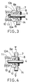
- the central axis of the conical outer surface 12a is displaced from the central axis of the spindle 10 by a short distance e2 as shown in FIG. 2, so that the outer surface 12a slidably contacts the inner wall 8a when the annular protrusion 12 is in engagement with the annular recess 8 as shown in FIG. 4.
- the diameter of the conical outer surface 12a is determined to be smaller than that of the conical inner wall 8a within the region where the outer surface 12a is within the outer wall 8a when the annular protrusion 12 is fully engaged with the annular recess 8 as shown in FIG. 4. Further, the displaced distance e2 of the outer surface 12a is determined to be smaller than the displaced distance e1 of the inner wall 8a.
- a compression spring 14 is interposed between the annular protrusion 12 of the spindle 10 and the main gear 7 so as to normally keep the annular protrusion 12 not to engage the annular recess 8 of the main gear 7.
- One end of the spring 14 is received within a recess 13 formed inside of the annular protrusion 12, and the other end of the compression spring 14 is received with in the annular recess 8 of the main gear 7.
- the annular protrusion 12 includes an end surface 12b which is opposed to the rear end of the metal bearing 11 in the axial direction.
- the end surface 12b is kept to slidably contact the rear end of the metal bearing 11 by the biasing force of the spring 14 when no axial load is applied to the spindle 10.
- the end surface 12b is separated from the rear end of the metal bearing 11 when the spindle 10 is axially moved against the force of the spring 14 and when the annular protrusion 12 is brought into engagement with the annular recess 8 of the main gear 7 for transmission of rotation.
- the annular protrusion 12 of the spindle 10 further includes a conical engaging surface 15 which is formed between the outer surface 12a and the end surface 12b.
- the diameter of the engaging surface 15 decreases in the forward direction, and the central axis of the engaging surface 15 is displaced from the central axis of the spindle 10 by a short distance.
- a ring 16 made of rubber is mounted within the gear housing 1a and is fixedly received within a space formed between the rear end of the metal bearing 11 and the inner surface of the gear housing 1a.
- the ring 16 includes a conical inner surface 16a.
- the central axis of the inner surface 16a is displaced from the central axis of the spindle 10 by the same distance as the central axis of the engaging surface 15.
- the inner surface 16a has the same inclination angle as that of the engaging surface 15.
- the engaging surface 15 is brought into engagement with the inner surface 16a of the ring 16 through its entire surface so as to prevent the spindle 10 from rotation when the spindle 10 is moved to disengage the annular protrusion 12 from the annular recess 8 and when the central axis of the engaging surface 15 coincides with the that of the inner surface 16a.
- a lock ring 17 is threadably engaged with the forward portion of the gear housing 1a, so that the position of the lock ring 17 is adjustable relative to the gear housing 1a in the axial direction.
- a tubular stopper sleeve 18 is fitted on the forward end of the lock ring 17 and the driver bit 9 extends through the stopper sleeve 18.
- a tubular dust-prevention member 19 is fitted within the forward portion of the lock ring 17 and extends over both the forward portion of the spindle 10 and the rear portion of the driver bit 9 so as to prevent entrance of dust into the gear housing 1a.
- an elongated stop member 20 made of synthetic resin such as nylon or a rubber is interposed between the forward portion of the gear housing 1a and the lock ring 17.
- the stop member 20 is partly received within a recess 21 formed on the forward portion of the gear housing 1a and frictionally contacts the inner surface of the lock ring 17 so as to keep the adjusted position of the lock ring 17.
- an operator rotates the lock ring 17 relative to the gear housing 1a so as to adjust the axial position of the stopper sleeve 18 in correspondence to the desired driving depth of a screw to be driven.
- the screw is thereafter fitted on the forward end of the driver bit 9 and the operator brings the screwdriver so as to abut the screw on a work.
- the annular protrusion 12 is kept in disengagement from the annular recess 8 of the main gear 7 by the biasing force of the spring 14. Therefore, when the motor is started, the rotation of the motor shaft 2 is not transmitted to the spindle 10 or the driver bit 9 although it is transmitted to the main gear 7.
- the spindle 10 When the operator moves the screwdriver to press the screw fitted on the driver bit 9 toward the work, the spindle 10 is moved together with the driver bit 9 in the axial direction toward the main gear 7 against the biasing force of the spring 14.
- the annular protrusion 12 of the spindle 10 is therefore moved to be engaged with the annular recess 8 in such a manner that, during rotation of the main gear 7 at the beginning of movement, the conical outer surface 12a intermittently contacts the conical inner wall 8a of the annular recess 8 by a part which is positioned most remotely from the central axis, and thereafter the conical outer surface 12a continuously contacts the inner wall 8a during rotation of the main gear 7 as the central axes of the inner wall 8a and the outer surface 12a are positioned in alignment with each other with respect to the central axis of the spindle 10.
- the screwdriver is moved toward the work as the screw is driven into the work and is stopped when the forward end of the stopper sleeve 18 abuts on the work.
- a smaller axial force or load is applied from the spindle 10 to the main gear 7 through the driver bit 9, so that the difference is produced between the rotational torque of the spindle 10 and that of the main gear 7. Consequently, the spindle 10 is moved forwardly by the biasing force of the spring 14 and the reaction force which may be produced between the outer surface 12a of the annular protrusion 12 of the spindle 10 and the inner wall 8a of the annular recess 8.
- the annular protrusion 12 is automatically disengaged from the annular recess 8, and the rotation of the main gear 7 is not transmitted to the spindle 10.
- the engaging surface 15 of the annular protrusion 12 is brought into contact with the inner surface 16a of the ring 16, so that the rotation of the spindle 10 is stopped through frictional force which may be produced between the engaging surface 15 and the inner surface 16a of the ring 16. Because of displacement of the central axes of the engaging surface 15 and the inner surface 16a from the central axis of the spindle 10, the rotation of the spindle 10 may be gradually reliably stopped.
- the annular protrusion 12 of the spindle 10 is kept in engagement with the annular recess 8 of the main gear 7 in such a manner that the outer surface 12a of the annular protrusion 12 and the inner wall 8a of the recess 8 continuously contact each other during rotation of the main gear 7.
- the screw is further tightened.
- the distance e2 of displacement of the outer surface 12a of the of the annular protrusion 12 is determined to be smaller than the distance e1 of displacement of the inner wall 8a of the main gear 7, the distance e2 and e1 may be equal to each other.
- the diameter of the conical outer surface 12a is determined to have a smaller diameter than that of the conical inner wall 8a within the region where the outer surface 12a is within the outer wall 8a when the annular portion 12 is fully engaged with the annular recess 8, they may be equal to each other. In such a case, the outer surface 12a and the inner wall 8a may contact each other throughout their entire surfaces.
- the recess 8 is formed on the main gear 7, and the annular protrusion 12, on the spindle 10, the recess 8 may be formed on the spindle 10, and the annular protrusion 12, on the main gear 7.
Landscapes
- Engineering & Computer Science (AREA)
- Mechanical Engineering (AREA)
- General Engineering & Computer Science (AREA)
- Details Of Spanners, Wrenches, And Screw Drivers And Accessories (AREA)
Applications Claiming Priority (2)
| Application Number | Priority Date | Filing Date | Title |
|---|---|---|---|
| JP154508/92 | 1992-05-20 | ||
| JP4154508A JP3071563B2 (ja) | 1992-05-20 | 1992-05-20 | スクリュードライバーにおけるクラッチ装置 |
Publications (1)
| Publication Number | Publication Date |
|---|---|
| EP0570902A1 true EP0570902A1 (en) | 1993-11-24 |
Family
ID=15585784
Family Applications (1)
| Application Number | Title | Priority Date | Filing Date |
|---|---|---|---|
| EP93108056A Withdrawn EP0570902A1 (en) | 1992-05-20 | 1993-05-18 | Power driven screwdriver |
Country Status (3)
| Country | Link |
|---|---|
| US (1) | US5271471A (ja) |
| EP (1) | EP0570902A1 (ja) |
| JP (1) | JP3071563B2 (ja) |
Cited By (3)
| Publication number | Priority date | Publication date | Assignee | Title |
|---|---|---|---|---|
| EP2127811A1 (en) * | 2008-05-27 | 2009-12-02 | Hitachi Koki CO., LTD. | Screw driver |
| EP2200772A4 (en) * | 2007-09-06 | 2011-04-27 | Demain Technology Pty Ltd | MECHANICAL ARRANGEMENT FOR A TOOL MACHINE |
| CN102528718A (zh) * | 2010-12-27 | 2012-07-04 | 株式会社牧田 | 作业工具 |
Families Citing this family (23)
| Publication number | Priority date | Publication date | Assignee | Title |
|---|---|---|---|---|
| JP2867107B2 (ja) * | 1994-02-03 | 1999-03-08 | 株式会社マキタ | 電動スクリュドライバのサイレントクラッチ |
| JP3628486B2 (ja) * | 1997-06-30 | 2005-03-09 | 株式会社マキタ | ねじ締め機のクラッチ |
| US7972337B2 (en) | 2005-12-28 | 2011-07-05 | Intrinsic Therapeutics, Inc. | Devices and methods for bone anchoring |
| US8323341B2 (en) | 2007-09-07 | 2012-12-04 | Intrinsic Therapeutics, Inc. | Impaction grafting for vertebral fusion |
| US6311787B1 (en) * | 2000-04-18 | 2001-11-06 | Black & Decker Inc. | Power driven rotary device |
| US6702090B2 (en) | 2001-03-14 | 2004-03-09 | Milwaukee Electric Tool Corporation | Power tool and spindle lock system |
| US6758116B2 (en) | 2001-06-28 | 2004-07-06 | Porter-Cable/Delta | Depth adjusting system for a screw gun |
| US7047848B2 (en) * | 2001-06-29 | 2006-05-23 | Portar-Cable/Delta | Manufacture of steel components for screw gun clutches |
| US6665923B2 (en) | 2001-06-29 | 2003-12-23 | Porter-Cable/Delta | Clutch for a screw gun and utilizing method |
| US7063201B2 (en) * | 2001-11-27 | 2006-06-20 | Milwaukee Electric Tool Corporation | Power tool and spindle lock system |
| DE10308272B4 (de) * | 2002-03-05 | 2012-05-24 | Makita Corp. | Schraubendreher |
| US6988027B2 (en) * | 2003-08-27 | 2006-01-17 | Honda Motor Co., Ltd. | Electric power steering system |
| JP2009101502A (ja) * | 2007-10-02 | 2009-05-14 | Hitachi Koki Co Ltd | ねじ締め機 |
| US7798245B2 (en) | 2007-11-21 | 2010-09-21 | Black & Decker Inc. | Multi-mode drill with an electronic switching arrangement |
| US7717192B2 (en) | 2007-11-21 | 2010-05-18 | Black & Decker Inc. | Multi-mode drill with mode collar |
| US7854274B2 (en) | 2007-11-21 | 2010-12-21 | Black & Decker Inc. | Multi-mode drill and transmission sub-assembly including a gear case cover supporting biasing |
| US7770660B2 (en) | 2007-11-21 | 2010-08-10 | Black & Decker Inc. | Mid-handle drill construction and assembly process |
| US7717191B2 (en) | 2007-11-21 | 2010-05-18 | Black & Decker Inc. | Multi-mode hammer drill with shift lock |
| US7762349B2 (en) | 2007-11-21 | 2010-07-27 | Black & Decker Inc. | Multi-speed drill and transmission with low gear only clutch |
| US7735575B2 (en) | 2007-11-21 | 2010-06-15 | Black & Decker Inc. | Hammer drill with hard hammer support structure |
| JP5099440B2 (ja) * | 2008-05-27 | 2012-12-19 | 日立工機株式会社 | ねじ締め機 |
| JP5585840B2 (ja) * | 2010-12-16 | 2014-09-10 | 日立工機株式会社 | ねじ締機 |
| JP6758853B2 (ja) * | 2016-02-22 | 2020-09-23 | 株式会社マキタ | アングル工具 |
Citations (5)
| Publication number | Priority date | Publication date | Assignee | Title |
|---|---|---|---|---|
| DE180023C (ja) * | ||||
| DE474971C (de) * | 1928-01-18 | 1929-04-16 | Ackermann & Schmitt | Steckschluessel zum Aufschrauben von Muttern |
| FR860195A (fr) * | 1939-06-14 | 1941-01-08 | S Van Der Windt & Cie | Perceuse électrique |
| DE1127173B (de) * | 1959-04-07 | 1962-04-05 | Schraubenfabrik Iarich Dembnyi | Spindelkasten an Drehmaschinen mit einer mit dem Antrieb und mit der Bremsvorrichtung kuppelbaren Arbeitsspindel |
| EP0476999A1 (en) * | 1990-09-19 | 1992-03-25 | Makita Corporation | Power driven screwdriver |
Family Cites Families (4)
| Publication number | Priority date | Publication date | Assignee | Title |
|---|---|---|---|---|
| US3205925A (en) * | 1962-12-20 | 1965-09-14 | Automatic Elect Lab | Brake mechanism for power screwdriver |
| US4647260A (en) * | 1984-03-15 | 1987-03-03 | Black & Decker Inc. | Depth-adjusting system for a power tool |
| DE3432382A1 (de) * | 1984-09-03 | 1986-03-13 | Hilti Ag, Schaan | Motorisch betriebenes schraubgeraet |
| DE8901499U1 (de) * | 1989-02-10 | 1989-04-06 | Kress-Elektrik GmbH & Co., 7457 Bisingen | Kraftangetriebenes Schraubwerkzeug |
-
1992
- 1992-05-20 JP JP4154508A patent/JP3071563B2/ja not_active Expired - Fee Related
-
1993
- 1993-05-18 US US08/063,458 patent/US5271471A/en not_active Expired - Fee Related
- 1993-05-18 EP EP93108056A patent/EP0570902A1/en not_active Withdrawn
Patent Citations (5)
| Publication number | Priority date | Publication date | Assignee | Title |
|---|---|---|---|---|
| DE180023C (ja) * | ||||
| DE474971C (de) * | 1928-01-18 | 1929-04-16 | Ackermann & Schmitt | Steckschluessel zum Aufschrauben von Muttern |
| FR860195A (fr) * | 1939-06-14 | 1941-01-08 | S Van Der Windt & Cie | Perceuse électrique |
| DE1127173B (de) * | 1959-04-07 | 1962-04-05 | Schraubenfabrik Iarich Dembnyi | Spindelkasten an Drehmaschinen mit einer mit dem Antrieb und mit der Bremsvorrichtung kuppelbaren Arbeitsspindel |
| EP0476999A1 (en) * | 1990-09-19 | 1992-03-25 | Makita Corporation | Power driven screwdriver |
Cited By (5)
| Publication number | Priority date | Publication date | Assignee | Title |
|---|---|---|---|---|
| EP2200772A4 (en) * | 2007-09-06 | 2011-04-27 | Demain Technology Pty Ltd | MECHANICAL ARRANGEMENT FOR A TOOL MACHINE |
| EP2127811A1 (en) * | 2008-05-27 | 2009-12-02 | Hitachi Koki CO., LTD. | Screw driver |
| US8146463B2 (en) | 2008-05-27 | 2012-04-03 | Hitachi Koki Co., Ltd. | Screw driver |
| CN102528718A (zh) * | 2010-12-27 | 2012-07-04 | 株式会社牧田 | 作业工具 |
| CN102528718B (zh) * | 2010-12-27 | 2015-04-01 | 株式会社牧田 | 作业工具 |
Also Published As
| Publication number | Publication date |
|---|---|
| JPH05318331A (ja) | 1993-12-03 |
| US5271471A (en) | 1993-12-21 |
| JP3071563B2 (ja) | 2000-07-31 |
Similar Documents
| Publication | Publication Date | Title |
|---|---|---|
| US5271471A (en) | Power driven screwdriver | |
| US4809572A (en) | Power driven screwdriver | |
| EP0476999B1 (en) | Power driven screwdriver | |
| US5209308A (en) | Power driven screwdriver | |
| CA1276818C (en) | Adjustable motor-operated screw driving device | |
| US5372206A (en) | Tightening tool | |
| US5778989A (en) | Screw driving tool | |
| JP2614371B2 (ja) | 携帯電気装置の動作を制御するための方法と構成 | |
| US5437524A (en) | Torque-adjustment controller | |
| US5947210A (en) | Power screwdriver | |
| US5310010A (en) | Automatic overload release and power stoppage device | |
| US4958840A (en) | Self disengaging keyless chuck | |
| US3834252A (en) | Adjustable positive clutch screwdriver | |
| US3398611A (en) | Electric hand tool with overload coupling | |
| US5601387A (en) | Depth adjusting system for a power tool | |
| US4368784A (en) | Power screwdriver | |
| EP0666145A1 (en) | Clutch mechanism in power driven screwdriver | |
| US5138916A (en) | Power operated screwdriver | |
| US6892611B2 (en) | Screwdriver | |
| US8708060B2 (en) | Clutch mechanisms for power screwdrivers | |
| US7188557B2 (en) | Tightening tool | |
| US4810138A (en) | Tap holder | |
| EP0719619B1 (en) | Screw tightening machine with clutch mechanism | |
| JP4428617B2 (ja) | トルク設定アダプタ | |
| JP3298944B2 (ja) | サイレントクラッチ付締付工具 |
Legal Events
| Date | Code | Title | Description |
|---|---|---|---|
| PUAI | Public reference made under article 153(3) epc to a published international application that has entered the european phase |
Free format text: ORIGINAL CODE: 0009012 |
|
| AK | Designated contracting states |
Kind code of ref document: A1 Designated state(s): DE FR GB |
|
| 17P | Request for examination filed |
Effective date: 19940107 |
|
| 17Q | First examination report despatched |
Effective date: 19941208 |
|
| 18D | Application deemed to be withdrawn |
Effective date: 19960405 |