EP0570935A1 - Vorrichtung zur Regelung der Kokillenoszillation bei einer Stranggiesskokille - Google Patents
Vorrichtung zur Regelung der Kokillenoszillation bei einer Stranggiesskokille Download PDFInfo
- Publication number
- EP0570935A1 EP0570935A1 EP93108171A EP93108171A EP0570935A1 EP 0570935 A1 EP0570935 A1 EP 0570935A1 EP 93108171 A EP93108171 A EP 93108171A EP 93108171 A EP93108171 A EP 93108171A EP 0570935 A1 EP0570935 A1 EP 0570935A1
- Authority
- EP
- European Patent Office
- Prior art keywords
- target
- signal
- horizontal position
- long
- offset value
- Prior art date
- Legal status (The legal status is an assumption and is not a legal conclusion. Google has not performed a legal analysis and makes no representation as to the accuracy of the status listed.)
- Granted
Links
Images





Classifications
-
- B—PERFORMING OPERATIONS; TRANSPORTING
- B22—CASTING; POWDER METALLURGY
- B22D—CASTING OF METALS; CASTING OF OTHER SUBSTANCES BY THE SAME PROCESSES OR DEVICES
- B22D11/00—Continuous casting of metals, i.e. casting in indefinite lengths
- B22D11/16—Controlling or regulating processes or operations
- B22D11/166—Controlling or regulating processes or operations for mould oscillation
-
- B—PERFORMING OPERATIONS; TRANSPORTING
- B22—CASTING; POWDER METALLURGY
- B22D—CASTING OF METALS; CASTING OF OTHER SUBSTANCES BY THE SAME PROCESSES OR DEVICES
- B22D11/00—Continuous casting of metals, i.e. casting in indefinite lengths
- B22D11/04—Continuous casting of metals, i.e. casting in indefinite lengths into open-ended moulds
- B22D11/053—Means for oscillating the moulds
- B22D11/0535—Means for oscillating the moulds in a horizontal plane
Definitions
- This invention relates to a control device for controlling oscillation on a mold in a continuous casting machine.
- Continuous casting process has been used for manufacturing slabs or billets from molten metal.
- the molten metal is first poured into a mold.
- the molten metal is covered with powder (lubricant) being sifted on the surface thereof.
- the mold is then cooled to quench the molten metal, which in turn is further cooled at a guide roll assembly.
- the metal solidifies completely at the guide roll assembly and drawn through pinch rolls.
- the molten metal in the mold is moved downward along the inner surface thereof as the solid metal is drawn off the casting station. In this event, the powder contributes to inhibiting air oxidation of the metal and trapping inclusions on the metal surface.
- the powder lies between the mold and the molten metal, which improves lubrication of their interface.
- the mold is shaken up and down repeatedly to reduce the damage on the inner surface of the mold caused by the direct contact with the metal. Though this vertical shaking is helpful for reducing the damage of the mold, it is not enough for effective inflow of the powder. Poor inflow of the powder badly affects the quality of end products and sometimes results in the sticking of the molten metal in the inner surface of the mold. This may cause a breakout of the mold as well as the molten loss hindering the effective casting of the metal.
- the mold comprises two long-side plates opposed to and in parallel with each other.
- the mold also comprises two short-side plates opposed to and in parallel with each other.
- the long-side and short-side plates construct the mold, which is surrounded by a rectangular mold frame with some distance away.
- the long-side plates move closer to and away from each other in synchronism with the vertical movement of the mold.
- the long-side plates are in the most close relation when they contact with the short-side plates. When the long-side plates are extremely distant, there is the largest space between the mold and the molten metal. The problem of poor inflow of the powder can thus be solved by means of moving the long-side plates quickly.
- the short-side plates are regarded to be constant in width though they expand and contract over the temperature difference.
- the extent of expansion and contraction depends on heat transferred from the molten metal, which affects the distance between the long-side and the short-side plates. Expansion of the short-side plates results in the smaller distance between the long-side and short-side plates. This reduces the distance for moving the long-side plates and thus the space between the long-side plates and the molten metal.
- the smaller space can receive less powder, which badly affects the quality of end products.
- poor inflow of the powder may be a cause of the sticking type, the breakout and the molten loss of the mold.
- contraction of the short-side plates increases the distance between the long-side and short-side plates. This may also cause the breakout due to the infiltration of the molten metal into the above mentioned gap.
- a sensor can be used for sensing the thermal expansion of the short-side plates to adjust the distance between the long-side and short-side plates.
- the sensor of this type is useful only when the thermal expansion on each component is quite equal in the mold. Thus it is usually impossible to determine positively the thermal expansion on various components of the mold.
- an object of the present invention is to provide a control device for controlling the horizontal oscillation of a mold in a continuous casting machine without being affected by the heat transferred from the molten metal.
- a control device controls the horizontal oscillation on a mold into which molten metal is poured in a continuous casting machine.
- the mold has a mold frame, two long-side plates opposed with each other, and two short-side plates extending orthogonal to the long-side plates.
- Each of the long-side plates is movably attached to the mold frame such that they can move horizontally through hydraulic cylinders and each of the hydraulic cylinders having a piston rod.
- the control device comprises position detecting means attached to the piston rod for detecting an actual position of the long-side plates to produce an actual horizontal position signal representing the detected actual position of the long-side plates.
- position detecting means connected to the position detecting means, supplied with a target horizontal position command, and given to a predetermined offset value, open-close control means produces a control signal by using the target horizontal position command, the actual horizontal position signal, and the predetermined offset value.
- the target horizontal position command represents a target horizontal position of the long-side plates and the target horizontal position varies from a target close position up to a target open position indicated as a function of time.
- the target close position can be considered as a reference position.
- the control signal indicates a deviation between the target horizontal position and the detected actual horizontal position.
- the open-close control means makes the deviation to be equal to the predetermined offset value when the target horizontal position is equal to the target close position.
- driving means drives the hydraulic cylinders according to the control signal.
- a mold 10 comprises a pair of long-side framing members 11 and a pair of short-side framing members 12.
- the long-side framing members 11 are opposed to and in parallel with each other.
- the short-side framing members 12 are also opposed to and in parallel with each other.
- Each of the short-side framing members 12 extends in the orthogonal direction to the long-side framing members 11.
- the long-side framing members 11 hold long-side copper plates 13 on the inner surfaces thereof, respectively, in contact relation therewith.
- the short-side framing members 12 hold short-side copper plates 14 on the inner surfaces thereof, respectively, in contact relation therewith.
- Each of the short-side framing members 12 is supported by a mold frame 15 through an adjusting rod 16.
- the mold frame 15 is rectangular in cross-section and surrounds the long-side and short side framing members with some distance away.
- One end of the rod 16 is attached to the short-side framing member 12.
- the other end of the rod penetrating through the mold frame 15 has a suitable member such as a nut 17 to adjust the length of the rod 16 extending within the mold frame 15.
- the distance between the short-side framing members 12 can be varied by means of losing and tightening the nuts 17.
- the long-side framing member 11 is larger in width than the long-side copper plate 13.
- Linear ball bearings 18 are disposed in four corners of the extending length of each framing member 11.
- the long-side framing members 11 are supported by the mold frame 15 through four guide rods 19 passing through the linear ball bearings 18. Both ends of the guide rod 19 are secured to the mold frame 15 through respective nuts 20, which allows the long-side framing members 11 to move in the direction closer to and away from each other.
- Four pairs of hydraulic cylinders 21 are provided within the mold frame 15, each of which comprises a piston rod 21a and a cylinder body 21b.
- the piston rod 21a is attached to the long-side framing member 11 near the linear ball bearing 18 while the cylinder body 21b is secured to the mold frame 15.
- the mold 10 is shaken up and down repeatedly in the direction indicated as "UP” and “DOWN” in Fig. 2.
- the long-side copper plates 13 move closer to and away from each other in synchronism with the vertical movement of the mold 10. In other words, the long-side copper plates 13 move in the direction indicated as “OPEN” and “CLOSE” in Fig. 2.
- the long-side plates 13 are in the most close relation when they contact with the short-side plates 14.
- FIG. 3 in addition to Figs. 1 and 2, a conventional control device is described in detail below. While only one control device is shown in Fig. 3, it should be understood that each of the eight hydraulic cylinders is associated with a similar control device.
- a horizontal position detector 22 is attached to the cylinder body 21b to determine an actual position of the long-side copper plate 13. In this event, the horizontal position detector 22 first detects a shift amount of the piston rod 21a and according to which it determines the position of the long-side copper plate 13. The horizontal position detector 22 produces an actual horizontal position signal Ph that represents the actual horizontal position of the long-side copper plate 13. The actual horizontal position signal Ph is supplied to an open-close control device 23' that is for moving the long-side copper plates 13 into relatively open and close positions.
- the open-close control device 23' is connected to a microcomputer (not shown) that produces a target horizontal position command Pc.
- the target horizontal position command Pc indicates a target horizontal position of the long-side copper plate 13 at every moment. In other words, the target horizontal position command Pc indicates an instantaneous position to which the long-side copper plate 13 should follow.
- the microcomputer is set various data indicating, e.g., the timing at which it begins to open or close the long-side copper plates 13 and target open and close positions thereof. In this event, the timing is determined relating to the vertical position of the mold 10.
- the long-side copper plates 13 can move horizontally in synchronism with the vertical movement of the mold 10 in a conventional manner.
- the open-close control device 23' receives the target horizontal position command Pc generated by the microcomputer and supplies an analog control signal to a servo-valve 24 through a servo-amplifier 25 such that the actual horizontal position of the long-side copper plate 12 comes up to the target horizontal position indicated by the target horizontal position command Pc.
- the servo-valve 24 is connected to a hydraulic unit 26 that will be described below.
- a combination of the servo-valve 24, the servo-amplifier 25 and the hydraulic unit 26 serves as a driving arrangement for driving the hydraulic cylinders 21. As shown in Fig.
- the open-close control device 23' comprises a digital input device (DI) 27, a subtractor 28, an amplifier (regulator) 29, and a digital/analog converter (D/A) 30.
- the digital input device 27 receives the actual horizontal position signal Ph as a digital input.
- the subtractor 28 subtracts the actual horizontal position signal Ph from the target horizontal position command Pc to produce an operational (or actuating) signal Op' representing a deviation between the actual and target positions of the long-side copper plate 13.
- the amplifier 29 acts as an adjusting unit for multiplying the operational signal Op' by a gain constant K to produce a digital control signal.
- the digital/analog converter 30 converts the digital control signal into the aforementioned analog control signal.
- the target horizontal position of the long-side copper plate 13 ranges from a target open position to a target close position as a function of time.
- the target open and close positions are fixed, which the latter generally corresponds to the position where the long-side copper plate 13 contacts the short-side copper plate 14.
- the target horizontal position of the long-side copper plate 13 is determined relating to the contact position between the long-side and short-side copper plates. Accordingly each long-side copper plate 13 is expected to move horizontally between the target open position and the target close position.
- the movement of the long-side copper plate 13 causes the change of distance between the long-side copper plate 13 and the short-side copper plate 14.
- the maximum open distance obtained under control of the open-close control device is referred as an actual span distance.
- the actual span distance corresponds to the distance between the actual open position of the long-side copper plate 13 and the actual position of the short-side copper plate 14 hence the use of term actual open position.
- a target span position is the distance between the target open position and the target close position.
- the expansion and contraction of the short-side copper plates 14 are not considered in the above mentioned control device 23'.
- the short-side copper plates 14 are regarded to be constant in width though they expand and contract over the temperature difference.
- the extent of expansion and contraction of the short-side copper plates 14 depends on heat transferred from the molten metal, which affects the actual span distance.
- Fig. 4 is a graphical representation showing, as a function of time, relation among target and actual positions of a long-side copper plate and an actual position of an expanded short-side copper plate when a conventional open-close control device is used.
- Fig. 5 is a graphical representation showing, as a function of time, relation among target and actual positions of a long-side copper plate and an actual position of a contracted short-side copper plate when a conventional open-close control device is used.
- a broken curve represents an actual position of the short-side copper plate 14.
- a triangular waveform of the broken dot line represents the target horizontal position of the long-side copper plate 13.
- a solid triangular waveform represents the actual position of the long-side copper plate 13.
- actual position of the short-side copper plate corresponds to the position of the transversal side of the plate 14 facing to the long-side copper plate 13.
- the target span distance corresponds to the distance between the upper and lower apexes of the triangle (broken dot line), i.e., the distance between the peak and valley.
- the distance between the top of the triangle (solid line) and the actual position of the short-side copper plate corresponds to the actual span distance.
- the actual horizontal position should follow the target horizontal position indicated by the target horizontal position command Pc.
- the long-side copper plate 13 can move horizontally only as much as the space defined to the short-side copper plate 14.
- the expansion of the short-side copper plate 14 results in reduction of the actual span distance. This is shown where the solid line overlays the broken curve.
- the actual span distance becomes shorter as the short-side copper plate 14 expands.
- the smaller space is available for the long-side copper plate 13 to travel, causing reduction of the space between the interfaces of the long-side copper plate 13 and the molten metal.
- the smaller space can receive less powder, which badly affects the quality of end products.
- Fig. 6 is a block diagram showing a control device for controlling mold horizontal oscillation according to an embodiment of the present invention.
- An open-close control device 23 in Fig. 6 is similar in structure and operation to the control device 23' illustrated in Fig. 3 other than an adder 31 and a reference position compensation circuit 32. Description of the similar components will thus be omitted by the consideration of avoiding redundancy.
- the adder 31 adds a compensation signal (described below) to the target horizontal position command Pc to produce a modified target position command.
- the compensation signal is for compensating the actual span distance varied as a result of the expansion and the contraction of the short-side copper plate 14.
- the modified target position command represents the modified target position of the long-side copper plate 13 and is supplied to the subtractor 28.
- the subtractor 28 subtracts the actual horizontal position signal Ph from the modified target position command to produce an operational (or an actuating) signal Op.
- the operational signal Op indicates a deviation between the actual horizontal position and the modified target position of the long-side copper plate 13 rather than the deviation relating to the target horizontal position thereof.
- the subtractor 28 supplies the operational signal Op to the reference position compensation circuit 32 as well as the amplifier 29.
- a combination of the adder 31 and the reference position compensation circuit 32 serves as a target position modifying arrangement for modifying the target horizontal position into a modified target position.
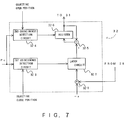
- the reference position compensation circuit 32 which comprises a subtractor 32-1, a latch circuit 32-2, a first coincidence detection circuit 32-3, a second coincidence detection circuit 32-4, an adder 32-5 and a register 32-6.
- a predetermined offset value "-a" (minus a)" is given to the subtractor 32-1.
- the subtractor 32-1 also receives the operational signal Op supplied from the subtractor 28.
- the subtractor 32-1 subtracts the operational signal Op from the predetermined offset value "-a” to supply the subtraction result to the latch circuit 32-2 as a shift signal.
- the shift signal corresponds to a shift amount of a target open position from the previous target open position.
- the latch circuit 32-2 latches the shift signal for a predetermined time interval.
- the first coincidence detection circuit 32-3 is supplied with the target horizontal position command Pc and a signal indicative of the target close position from the microcomputer (not shown).
- the first coincidence detection circuit 32-3 produces a first coincidence detection signal when the target horizontal position comes up to the target close position.
- the latch circuit 32-2 latches the shift signal as a latched signal that is supplied to the adder 32-5.
- the adder 32-5 adds the latched signal to an accumulated signal (described below) supplied from the register 32-6 to produce an addition signal.
- the register 32-6 supplies the accumulated signal as the compensation signal to the adder 31.
- the second coincidence detection circuit 32-4 is supplied with the target horizontal position command Pc and a signal indicative of the target open position from the microcomputer.
- the register 32-6 stores the addition signal as the stored signal to supply the same to the adder 32-5 as the accumulated signal.
- a combination of the subtractor 32-1, the latch circuit 32-2 and the first coincidence detection circuit 32-3 acts as a comparing arrangement while that of the second coincidence detection circuit 32-4, the adder 32-5 and the register 32-6 serves as an accumulating arrangement.
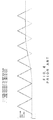
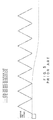
- Figs. 8 and 9 are view similar to Figs. 4 and 5 except that the broken dot line represents a waveform for the modified target position of the long-side copper plate 13.
- the register 32-6 initially stores the offset value "-a" as the stored signal.
- the reference position compensation circuit initially produces the offset value "-a” as the compensation signal.
- the modified target position of the long-side copper plate 13 is initially defined inside the target close position. In other word, the modified target position is shifted backward the target close position by an amount "a" relating to the open direction of the long-side copper plates. This is clearly shown in Figs. 8 and 9.
- the offset is indicated as “a” rather than "-a” at a time instance t0, this is attributed only to that a difference between two points can be represented only as a positive value. Accordingly it should be considered that the offset value supplied to the subtractor 32-1 (Fig. 7) has a negative value, i.e., "-a" in this embodiment.
- the distance between two long-side copper plates 13 will never be shorter than the width of the short-side copper plates 14.
- a distance "b1" represents a difference between the actual close position and the modified target close position at a time instance t1.
- the operational signal Op represents the deviation "-b1” because the operational signal Op is obtained by subtracting the actual position from the target position.
- the shift signal supplied from the subtractor 32-1 thus represents "-a - (-b1)” or "b1 - a”. This value of the shift signal is represented as a1 in Fig. 8.
- the time instance t1 corresponds to the timing when the first coincidence detection circuit 32-3 detects that the target horizontal position comes up to the target close position.
- the latch circuit 32-2 latches the shift signal a1 as the latched signal that is supplied to the adder 32-5.
- the adder adds the latched signal a1 to the accumulated signal.
- the register 32-6 stores the accumulated signal that represents "-a” at that moment, it is supplied with the addition signal indicative of "-a+ ⁇ 1".
- the second coincidence detection circuit produces the second coincidence detection signal. This corresponds to a time instance t2 in Fig. 8.
- the register 32-6 stores the compensation signal "-a+ ⁇ 1" as the accumulated signal which, in turn, is supplied to the adder 31 as the compensation signal.
- the adder 31 is supplied with the target horizontal position command Pc, so that the value of the compensation signal is obtained relating to the target close position (reference position) not being shifted.
- the modified target position is, however, shifted by "-a" beforehand. Accordingly, the modified target position is increased by ⁇ 1.
- the operational signal Op obtained at a time instance t3 represents the deviation "-b2".
- the shift signal supplied from the subtractor 32-1 thus represents "-a - (-b2)" or "b2 - a”.
- This value of the shift signal is represented as ⁇ 2 in Fig. 8.
- the latch circuit 32-2 latches the shift signal ⁇ 2 as the latched signal that is supplied to the adder 32-5.
- the adder 32-5 adds the latched signal ⁇ 2 to the accumulated signal. More particularly, the compensation signal to be stored in the register is equal to "-a + ⁇ 1+ ⁇ 2" because the accumulated signal at that moment represents "-a + ⁇ 1".
- the compensation signal "-a” + ⁇ 1 + ⁇ 2" is supplied from the register 32-6 at a time instance t4 to the adder 31 and the modified target position is increased by ⁇ 2.
- the shift signal supplied at a time instance t5 represents "-a - (-b3)" or "b3 - a”.
- This value of the shift signal is represented as ⁇ 3 and the compensation signal "-a + ⁇ 1 + ⁇ 2 + ⁇ 3" is supplied from the register 32-6 at a time instance t6 to the adder 31 and the modified target position is further increased by ⁇ 3.
- the deviation becomes equal to the offset value, so that it is unnecessary to shift the modified target position at a time instance t8. In this way, it becomes possible to ensure the actual span distance despite the expansion of the short-side copper plate 14.
- a distance "C1" represents a difference between the actual close position and the modified target close position at a time instance t1.
- the operational signal Op represents the deviation "-C1” because the operational signal Op is obtained by subtracting the actual position from the target position as in the above mentioned case.
- the shift signal supplied from the subtractor 32-1 represents "-a - (-C1)” corresponding to "- ⁇ 1".
- the value of "- ⁇ 1” becomes negative because an amount of "C” is smaller than that of "a”.
- " ⁇ 1" in Fig. 9 represents a difference between two points, so that is indicated as "a - C1" rather than "C1 - a".
- the latch circuit 32-2 latches the shift signal " ⁇ 1" as the latched signal that is supplied to the adder 32-5.
- the adder 32-5 adds the shift signal " ⁇ 1" to the accumulated signal.
- the register 32-6 stores the accumulated signal representing "-a” at that moment, so that the compensation signal to be stored in the register is equal to "-a - ⁇ 1".
- the compensation signal "-a- ⁇ 1" is supplied from the register 32-6 to the adder 31 at a time instance t2. Accordingly, the modified target position is decreased by " ⁇ 1".
- the operational signal Op obtained at a time instance t3 represents the deviation "-C2" and the shift signal supplied from the subtractor 32-1 is represented as "- ⁇ 2".
- the compensation signal "-a - ⁇ 1 - ⁇ 2" is supplied from the register 32-6 to the adder 31 at a time instance t4 and the modified target position is decreased by " ⁇ 2".
- the shift signal supplied at a time instance t5 is represented as " ⁇ 3” and the compensation signal "-a - ⁇ 1 - ⁇ 2 - ⁇ 3" is supplied from the register 32-6 to the adder 31 at a time instance t6. Consequently, the modified target position is further decreased by " ⁇ 3" This continues until the deviation between the modified target position and the actual position of the long-side copper plate 13 becomes equal.
- the offset value is one of the outstanding features of the present invention.
- the amount of the offset value in practice depends on the speed (referred to as a follow speed) at which the actual position of the long-side copper plate 13 follows the modified target position.
- the offset value may theoretically be any suitable value as long as the absolute value (magnitude) of the offset is larger than the deviation between the actual and target position at a certain time instance when the actual position of the long-side copper plate 13 is not affected by the short-side copper plate 14. Such deviation is referred to as a follow distance below.
- the offset value can accordingly be a value that satisfies the condition,
- the absolute value of the offset is sufficiently larger than the follow distance to yield a desired result in a reasonable time.
- the reason is that the upper apex (i.e., the target open position) of the waveform is shifted by an amount equal to the difference between the absolute value of the offset and the follow distance.
- the absolute value of the offset is about 3.5 times larger than the follow distance in the above embodiment.
Landscapes
- Engineering & Computer Science (AREA)
- Mechanical Engineering (AREA)
- Continuous Casting (AREA)
- Control Of Position Or Direction (AREA)
Applications Claiming Priority (2)
| Application Number | Priority Date | Filing Date | Title |
|---|---|---|---|
| JP128502/92 | 1992-05-21 | ||
| JP04128502A JP3077006B2 (ja) | 1992-05-21 | 1992-05-21 | 連続鋳造設備における鋳型水平振動制御装置 |
Publications (2)
| Publication Number | Publication Date |
|---|---|
| EP0570935A1 true EP0570935A1 (de) | 1993-11-24 |
| EP0570935B1 EP0570935B1 (de) | 1998-02-25 |
Family
ID=14986333
Family Applications (1)
| Application Number | Title | Priority Date | Filing Date |
|---|---|---|---|
| EP93108171A Expired - Lifetime EP0570935B1 (de) | 1992-05-21 | 1993-05-19 | Vorrichtung zur Regelung der Kokillenoszillation bei einer Stranggiesskokille |
Country Status (5)
| Country | Link |
|---|---|
| US (1) | US5350005A (de) |
| EP (1) | EP0570935B1 (de) |
| JP (1) | JP3077006B2 (de) |
| AT (1) | ATE163375T1 (de) |
| DE (1) | DE69317068T2 (de) |
Cited By (4)
| Publication number | Priority date | Publication date | Assignee | Title |
|---|---|---|---|---|
| EP0649692A1 (de) * | 1993-10-21 | 1995-04-26 | Hitachi Zosen Corporation | Kokillenoszilliervorrichtung in einer Stranggiessanlage |
| EP0618023A4 (de) * | 1992-09-22 | 1996-10-23 | Kawasaki Steel Co | Verfahren zum kontinuierlichen giessen von brammen. |
| US5623983A (en) * | 1994-12-21 | 1997-04-29 | Voest-Alpine Industrieanlagenbau Gmbh | Continuous casting mold |
| US20100294125A1 (en) * | 2007-10-30 | 2010-11-25 | Siemens Aktiengesellschaft | Control device for the position control of a hydraulic cylinder unit comprising a linearization unit |
Families Citing this family (8)
| Publication number | Priority date | Publication date | Assignee | Title |
|---|---|---|---|---|
| DE4341719C2 (de) * | 1993-12-03 | 2001-02-01 | Mannesmann Ag | Einrichtung zum Stranggießen von Stahl |
| IT1267209B1 (it) * | 1993-12-20 | 1997-01-28 | Voest Alpine Ind Anlagen | Conchiglia per colata continua. |
| JP2932235B2 (ja) * | 1994-02-04 | 1999-08-09 | 住友重機械工業株式会社 | 連続鋳造機のモールドオッシレーション装置 |
| AT404442B (de) * | 1994-12-21 | 1998-11-25 | Voest Alpine Ind Anlagen | Stranggiesskokille |
| KR101243118B1 (ko) * | 2009-10-01 | 2013-03-12 | 주식회사 포스코 | 에지댐 진동 제어방법 및 제어장치 |
| CN106102959B (zh) * | 2014-02-14 | 2018-04-03 | 丹尼尔和科菲森梅克尼齐有限公司 | 用于振动工作台的控制设备 |
| ES2562859B1 (es) * | 2015-08-11 | 2016-12-22 | Sarralle Equipos Siderúrgicos, S.L. | Sistema de control de los cilindros de oscilación de un molde para colada continua |
| DE102017201496A1 (de) | 2017-01-31 | 2018-08-02 | Sms Group Gmbh | Oszillationssystem für eine Stranggießkokille, und Verfahren zum Erzeugen einer Oszillationsbewegung einer Stranggießkokille |
Citations (6)
| Publication number | Priority date | Publication date | Assignee | Title |
|---|---|---|---|---|
| EP0124362A1 (de) * | 1983-04-28 | 1984-11-07 | Uss Engineers And Consultants, Inc. | System zur Anzeige der Belastung der Oszillationseinrichtung einer Stranggiesskokille |
| EP0121622B1 (de) * | 1983-03-07 | 1988-02-24 | KABUSHIKI KAISHA KOBE SEIKO SHO also known as Kobe Steel Ltd. | Verfahren und Einrichtung zum Stranggiessen unter Verwendung einer oszillierenden Form |
| DE3632333A1 (de) * | 1986-09-24 | 1988-03-31 | Voest Alpine Ag | Vorrichtung zum ueberwachen der schwingungen einer stranggiesskokille |
| US4762164A (en) * | 1987-08-20 | 1988-08-09 | Usx Corporation | Mold friction monitoring for breakout protection |
| EP0372506A2 (de) * | 1988-12-08 | 1990-06-13 | Kawasaki Steel Corporation | Kokillen-Oszillationsverfahren für Vertikalstranggussanlage |
| EP0325931B1 (de) * | 1988-01-28 | 1992-04-22 | Clecim | Verfahren und Vorrichtung zum Oszillieren einer Stahlstranggiesskokille |
Family Cites Families (1)
| Publication number | Priority date | Publication date | Assignee | Title |
|---|---|---|---|---|
| JP2589382B2 (ja) * | 1989-09-11 | 1997-03-12 | 川崎製鉄株式会社 | 連続鋳造設備における鋳型振動装置 |
-
1992
- 1992-05-21 JP JP04128502A patent/JP3077006B2/ja not_active Expired - Lifetime
-
1993
- 1993-05-19 DE DE69317068T patent/DE69317068T2/de not_active Expired - Fee Related
- 1993-05-19 AT AT93108171T patent/ATE163375T1/de not_active IP Right Cessation
- 1993-05-19 EP EP93108171A patent/EP0570935B1/de not_active Expired - Lifetime
- 1993-05-21 US US08/064,436 patent/US5350005A/en not_active Expired - Fee Related
Patent Citations (6)
| Publication number | Priority date | Publication date | Assignee | Title |
|---|---|---|---|---|
| EP0121622B1 (de) * | 1983-03-07 | 1988-02-24 | KABUSHIKI KAISHA KOBE SEIKO SHO also known as Kobe Steel Ltd. | Verfahren und Einrichtung zum Stranggiessen unter Verwendung einer oszillierenden Form |
| EP0124362A1 (de) * | 1983-04-28 | 1984-11-07 | Uss Engineers And Consultants, Inc. | System zur Anzeige der Belastung der Oszillationseinrichtung einer Stranggiesskokille |
| DE3632333A1 (de) * | 1986-09-24 | 1988-03-31 | Voest Alpine Ag | Vorrichtung zum ueberwachen der schwingungen einer stranggiesskokille |
| US4762164A (en) * | 1987-08-20 | 1988-08-09 | Usx Corporation | Mold friction monitoring for breakout protection |
| EP0325931B1 (de) * | 1988-01-28 | 1992-04-22 | Clecim | Verfahren und Vorrichtung zum Oszillieren einer Stahlstranggiesskokille |
| EP0372506A2 (de) * | 1988-12-08 | 1990-06-13 | Kawasaki Steel Corporation | Kokillen-Oszillationsverfahren für Vertikalstranggussanlage |
Cited By (6)
| Publication number | Priority date | Publication date | Assignee | Title |
|---|---|---|---|---|
| EP0618023A4 (de) * | 1992-09-22 | 1996-10-23 | Kawasaki Steel Co | Verfahren zum kontinuierlichen giessen von brammen. |
| EP0649692A1 (de) * | 1993-10-21 | 1995-04-26 | Hitachi Zosen Corporation | Kokillenoszilliervorrichtung in einer Stranggiessanlage |
| US5458182A (en) * | 1993-10-21 | 1995-10-17 | Hitachi Zosen Corporation | Mold vibrating apparatus in continuous casting equipment |
| US5623983A (en) * | 1994-12-21 | 1997-04-29 | Voest-Alpine Industrieanlagenbau Gmbh | Continuous casting mold |
| US20100294125A1 (en) * | 2007-10-30 | 2010-11-25 | Siemens Aktiengesellschaft | Control device for the position control of a hydraulic cylinder unit comprising a linearization unit |
| US8301276B2 (en) * | 2007-10-30 | 2012-10-30 | Siemens Aktiengesellschaft | Control device for the position control of a hydraulic cylinder unit comprising a linearization unit |
Also Published As
| Publication number | Publication date |
|---|---|
| JPH05318067A (ja) | 1993-12-03 |
| ATE163375T1 (de) | 1998-03-15 |
| JP3077006B2 (ja) | 2000-08-14 |
| US5350005A (en) | 1994-09-27 |
| DE69317068T2 (de) | 1998-06-18 |
| DE69317068D1 (de) | 1998-04-02 |
| EP0570935B1 (de) | 1998-02-25 |
Similar Documents
| Publication | Publication Date | Title |
|---|---|---|
| US5350005A (en) | Control device for controlling mold oscillation in a continuous casting machine | |
| US5762127A (en) | Method to control the deformations of the sidewalls of a crystalliser and continuous-casting crystalliser | |
| US5913357A (en) | Method for controlling the level of molten metal for a continuous casting machine | |
| US5709261A (en) | Billet guiding unit of a continuous casting plant for thin slabs | |
| US6470957B1 (en) | Process for casting a continuous metal strand | |
| US5613390A (en) | Corner reduction device equipped with corner rolls, control device thereof, and method of rolling by using these devices | |
| US5947184A (en) | Equipment for continuous casting of metals | |
| JPH0985407A (ja) | 連続鋳造機におけるモールド内溶鋼レベル制御方法 | |
| US5297612A (en) | Method for controlling the clamping forces exerted on a continuous casting mold | |
| JPH0751264B2 (ja) | 連続鋳造機の鋳込み制御装置および制御方法 | |
| CA2002407A1 (en) | Method and apparatus for adjusting, during casting, of a mould in a continuous metal casting process | |
| US5190717A (en) | Metal pouring system | |
| US5090603A (en) | Metal pouring system | |
| JP3041591B2 (ja) | 連続鋳造用鋳片支持案内ロールの間隔変更方法及びその装置 | |
| US4756356A (en) | Method for controlling internal pressure in mold cavity in moving-mold type continuous casting machine | |
| JPS60148B2 (ja) | バルジング制御連続鋳造方法 | |
| JPH1128558A (ja) | 連鋳機内鋳片成形方法 | |
| JPS61269964A (ja) | 型締力自動調整装置 | |
| JP2835191B2 (ja) | 連続鋳造機における鋳型内湯面レベル制御装置 | |
| JP2960011B2 (ja) | 圧延における加減速時の板厚制御方法および制御装置 | |
| SU1276435A1 (ru) | Способ регулировани соосности кристаллизатора и поддерживающей секции зоны вторичного охлаждени и устройство дл его осуществлени | |
| KR200180084Y1 (ko) | 차단 설정값 보상기능을 구비한 연주 래들 슬래그 차단장치 | |
| EP1260290B1 (de) | Verfahren zum Detektieren von Materialausbuchtungen am Stranggut | |
| JPH05277688A (ja) | モールドレベル制御装置 | |
| JPH05245589A (ja) | 竪型連続鋳造用鋳型の振動方法 |
Legal Events
| Date | Code | Title | Description |
|---|---|---|---|
| PUAI | Public reference made under article 153(3) epc to a published international application that has entered the european phase |
Free format text: ORIGINAL CODE: 0009012 |
|
| AK | Designated contracting states |
Kind code of ref document: A1 Designated state(s): AT DE FR GB |
|
| 17P | Request for examination filed |
Effective date: 19940128 |
|
| 17Q | First examination report despatched |
Effective date: 19960115 |
|
| GRAG | Despatch of communication of intention to grant |
Free format text: ORIGINAL CODE: EPIDOS AGRA |
|
| GRAG | Despatch of communication of intention to grant |
Free format text: ORIGINAL CODE: EPIDOS AGRA |
|
| GRAH | Despatch of communication of intention to grant a patent |
Free format text: ORIGINAL CODE: EPIDOS IGRA |
|
| GRAH | Despatch of communication of intention to grant a patent |
Free format text: ORIGINAL CODE: EPIDOS IGRA |
|
| GRAA | (expected) grant |
Free format text: ORIGINAL CODE: 0009210 |
|
| AK | Designated contracting states |
Kind code of ref document: B1 Designated state(s): AT DE FR GB |
|
| REF | Corresponds to: |
Ref document number: 163375 Country of ref document: AT Date of ref document: 19980315 Kind code of ref document: T |
|
| REF | Corresponds to: |
Ref document number: 69317068 Country of ref document: DE Date of ref document: 19980402 |
|
| ET | Fr: translation filed | ||
| PLBE | No opposition filed within time limit |
Free format text: ORIGINAL CODE: 0009261 |
|
| 26N | No opposition filed | ||
| REG | Reference to a national code |
Ref country code: GB Ref legal event code: IF02 |
|
| PGFP | Annual fee paid to national office [announced via postgrant information from national office to epo] |
Ref country code: FR Payment date: 20020508 Year of fee payment: 10 |
|
| PGFP | Annual fee paid to national office [announced via postgrant information from national office to epo] |
Ref country code: AT Payment date: 20020513 Year of fee payment: 10 |
|
| PGFP | Annual fee paid to national office [announced via postgrant information from national office to epo] |
Ref country code: GB Payment date: 20020515 Year of fee payment: 10 |
|
| PGFP | Annual fee paid to national office [announced via postgrant information from national office to epo] |
Ref country code: DE Payment date: 20020522 Year of fee payment: 10 |
|
| PG25 | Lapsed in a contracting state [announced via postgrant information from national office to epo] |
Ref country code: GB Free format text: LAPSE BECAUSE OF NON-PAYMENT OF DUE FEES Effective date: 20030519 Ref country code: AT Free format text: LAPSE BECAUSE OF NON-PAYMENT OF DUE FEES Effective date: 20030519 |
|
| PG25 | Lapsed in a contracting state [announced via postgrant information from national office to epo] |
Ref country code: DE Free format text: LAPSE BECAUSE OF NON-PAYMENT OF DUE FEES Effective date: 20031202 |
|
| GBPC | Gb: european patent ceased through non-payment of renewal fee |
Effective date: 20030519 |
|
| PG25 | Lapsed in a contracting state [announced via postgrant information from national office to epo] |
Ref country code: FR Free format text: LAPSE BECAUSE OF NON-PAYMENT OF DUE FEES Effective date: 20040130 |
|
| REG | Reference to a national code |
Ref country code: FR Ref legal event code: ST |