EP0570964A2 - Données d'identification d'un signal vidéo - Google Patents
Données d'identification d'un signal vidéo Download PDFInfo
- Publication number
- EP0570964A2 EP0570964A2 EP93108216A EP93108216A EP0570964A2 EP 0570964 A2 EP0570964 A2 EP 0570964A2 EP 93108216 A EP93108216 A EP 93108216A EP 93108216 A EP93108216 A EP 93108216A EP 0570964 A2 EP0570964 A2 EP 0570964A2
- Authority
- EP
- European Patent Office
- Prior art keywords
- recording
- video signal
- video
- signal
- television standards
- Prior art date
- Legal status (The legal status is an assumption and is not a legal conclusion. Google has not performed a legal analysis and makes no representation as to the accuracy of the status listed.)
- Granted
Links
Images




Classifications
-
- G—PHYSICS
- G11—INFORMATION STORAGE
- G11B—INFORMATION STORAGE BASED ON RELATIVE MOVEMENT BETWEEN RECORD CARRIER AND TRANSDUCER
- G11B5/00—Recording by magnetisation or demagnetisation of a record carrier; Reproducing by magnetic means; Record carriers therefor
- G11B5/02—Recording, reproducing, or erasing methods; Read, write or erase circuits therefor
- G11B5/09—Digital recording
-
- G—PHYSICS
- G11—INFORMATION STORAGE
- G11B—INFORMATION STORAGE BASED ON RELATIVE MOVEMENT BETWEEN RECORD CARRIER AND TRANSDUCER
- G11B15/00—Driving, starting or stopping record carriers of filamentary or web form; Driving both such record carriers and heads; Guiding such record carriers or containers therefor; Control thereof; Control of operating function
- G11B15/18—Driving; Starting; Stopping; Arrangements for control or regulation thereof
- G11B15/1808—Driving of both record carrier and head
- G11B15/1875—Driving of both record carrier and head adaptations for special effects or editing
-
- G—PHYSICS
- G11—INFORMATION STORAGE
- G11B—INFORMATION STORAGE BASED ON RELATIVE MOVEMENT BETWEEN RECORD CARRIER AND TRANSDUCER
- G11B15/00—Driving, starting or stopping record carriers of filamentary or web form; Driving both such record carriers and heads; Guiding such record carriers or containers therefor; Control thereof; Control of operating function
- G11B15/02—Control of operating function, e.g. switching from recording to reproducing
- G11B15/05—Control of operating function, e.g. switching from recording to reproducing by sensing features present on or derived from record carrier or container
- G11B15/087—Control of operating function, e.g. switching from recording to reproducing by sensing features present on or derived from record carrier or container by sensing recorded signals
-
- G—PHYSICS
- G11—INFORMATION STORAGE
- G11B—INFORMATION STORAGE BASED ON RELATIVE MOVEMENT BETWEEN RECORD CARRIER AND TRANSDUCER
- G11B27/00—Editing; Indexing; Addressing; Timing or synchronising; Monitoring; Measuring tape travel
- G11B27/02—Editing, e.g. varying the order of information signals recorded on, or reproduced from, record carriers
- G11B27/031—Electronic editing of digitised analogue information signals, e.g. audio or video signals
- G11B27/032—Electronic editing of digitised analogue information signals, e.g. audio or video signals on tapes
-
- G—PHYSICS
- G11—INFORMATION STORAGE
- G11B—INFORMATION STORAGE BASED ON RELATIVE MOVEMENT BETWEEN RECORD CARRIER AND TRANSDUCER
- G11B27/00—Editing; Indexing; Addressing; Timing or synchronising; Monitoring; Measuring tape travel
- G11B27/10—Indexing; Addressing; Timing or synchronising; Measuring tape travel
- G11B27/19—Indexing; Addressing; Timing or synchronising; Measuring tape travel by using information detectable on the record carrier
- G11B27/28—Indexing; Addressing; Timing or synchronising; Measuring tape travel by using information detectable on the record carrier by using information signals recorded by the same method as the main recording
- G11B27/30—Indexing; Addressing; Timing or synchronising; Measuring tape travel by using information detectable on the record carrier by using information signals recorded by the same method as the main recording on the same track as the main recording
- G11B27/3027—Indexing; Addressing; Timing or synchronising; Measuring tape travel by using information detectable on the record carrier by using information signals recorded by the same method as the main recording on the same track as the main recording used signal is digitally coded
-
- H—ELECTRICITY
- H04—ELECTRIC COMMUNICATION TECHNIQUE
- H04N—PICTORIAL COMMUNICATION, e.g. TELEVISION
- H04N5/00—Details of television systems
- H04N5/76—Television signal recording
- H04N5/78—Television signal recording using magnetic recording
- H04N5/782—Television signal recording using magnetic recording on tape
- H04N5/7824—Television signal recording using magnetic recording on tape with rotating magnetic heads
- H04N5/7826—Television signal recording using magnetic recording on tape with rotating magnetic heads involving helical scanning of the magnetic tape
- H04N5/78263—Television signal recording using magnetic recording on tape with rotating magnetic heads involving helical scanning of the magnetic tape for recording on tracks inclined relative to the direction of movement of the tape
- H04N5/78266—Television signal recording using magnetic recording on tape with rotating magnetic heads involving helical scanning of the magnetic tape for recording on tracks inclined relative to the direction of movement of the tape using more than one track for the recording of one television field or frame, i.e. segmented recording
-
- G—PHYSICS
- G11—INFORMATION STORAGE
- G11B—INFORMATION STORAGE BASED ON RELATIVE MOVEMENT BETWEEN RECORD CARRIER AND TRANSDUCER
- G11B2220/00—Record carriers by type
- G11B2220/90—Tape-like record carriers
-
- H—ELECTRICITY
- H04—ELECTRIC COMMUNICATION TECHNIQUE
- H04N—PICTORIAL COMMUNICATION, e.g. TELEVISION
- H04N5/00—Details of television systems
- H04N5/76—Television signal recording
- H04N5/91—Television signal processing therefor
- H04N5/92—Transformation of the television signal for recording, e.g. modulation, frequency changing; Inverse transformation for playback
- H04N5/9201—Transformation of the television signal for recording, e.g. modulation, frequency changing; Inverse transformation for playback involving the multiplexing of an additional signal and the video signal
- H04N5/9206—Transformation of the television signal for recording, e.g. modulation, frequency changing; Inverse transformation for playback involving the multiplexing of an additional signal and the video signal the additional signal being a character code signal
Definitions
- This invention relates to a video tape recorder, and more particularly to a video tape recorder in which a video signal is converted into a digital signal to be recorded and reproduced.
- Some conventional video tape recorders are adapted to convert video signal into digital signal (hereinafter referred to as digital video signal) to be recorded and reproduced.
- deterioration in picture quality may be previously prevented in digital video signal even if signal processing is repeated, deterioration in picture quality in the reproduced picture may be previously prevented no matter how many times dubbing is repeated in a manner combined with error correction processing or the like.
- the amount of data is increased comparing to the case where the video signal is recorded in the format of an analog signal.
- segment-recording refers to a recording method in which digital video signal corresponding to one field is recorded in a manner being allocated to a plurality of recording tracks and which is used to previously prevent an increase in the amount of data per one track.
- a rotary drum is constructed so that a plurality of magnetic heads scan the recording tracks substantially simultaneously whereby digital video signal corresponding to one field is recorded in a cycle consisting of one half rotation or one full rotation of the rotary drum.
- the operation mode even in the case of segment-recording, may be switched from reproduction mode to recording mode in synchronization with the rotation of the rotary drum to smoothly perform consecutive taking in picture recording.
- the method may be considered in which the rotating speed of the rotary drum is increased and thereby the same single magnetic head is used to form recording tracks repeatedly during the time period of one field.
- an object of this invention is to provide a video tape recorder in which, in the case of segment-recording, consecutive taking in picture recording may be performed smoothly.
- the first aspect of the invention has been achieved by the provision of video tape recorder 1, generating recording signal S REC by performing a video signal SV to digital signal processing in predetermined units of signal processing to record in segments the video signal SV onto recording tracks TA, TB, ...
- the video signal SV is recorded with identification data ID which changes by each unit of signal processing when the video signal SV is to be recorded; switching to reproduction mode is effected at the time of starting recording after rewinding the magnetic tape T by a predetermined distance; a break between units of signal processing is detected on the basis of the identification data ID reproduced from the reproducing tracks TA, TB, ...; and switching from the reproduction mode to recording mode is made at the break between the units of signal processing.
- the second aspect of the invention has been achieved by the provision of video tape recorder 1, generating recording signal S REC by performing video signals SV of the normal television standards and the high definition television standards to digital signal processing respectively in predetermined units of signal processing to record in segments the video signals SV of the normal television standards and the high definition television standards onto recording tracks TA, TB, ...
- the video signals SV are recorded with a first identification data ID which changes by each unit of signal processing and a second identification data ID for identifying the video signal SV of the normal television standards and the video signal SV of the high definition television standards when the video signal SV of the normal television standards and the video signal SV of the high definition television standards are to be recorded; switching to reproduction mode is effected after rewinding the magnetic tape T by a predetermined distance at the time of starting recording of the video signal SV of the normal television standards and the video signal SV of the high definition television standards; a break between units of signal processing is detected on the basis of the first and the second identification data ID which are reproduced from the recording tracks TA, TB, ...; and switching from said reproduction mode to recording mode is effected at the break between the units of signal processing.
- the third aspect of the invention has been achieved by the provision of video tape recorder 1, generating a recording signal S REC by performing video signal SV to digital video signal processing in predetermined unit of signal processing which varies according to recording mode, to record in segments the video signal SV onto recording tracks TA, TB, ...
- the video signal SV is recorded with a first identification data ID which changes by each unit of signal processing and a third identification data ID for identifying the recording mode when the video signal SV is to be recorded; switching to reproduction mode is effected after rewinding the magnetic tape T by a predetermined distance at the time of starting recording of the video signal SV; a break between units of signal processing is detected on the basis of the first and the third identification data ID reproduced from the recording tracks TA, TB, ..., and switching from said reproduction mode to recording mode is effected at the break between the units of signal processing.
- picture recording may be securely started at a break between units of signal processing, thereby consecutive taking in picture recording may be performed smoothly.
- a video signal is segment-recorded with identification data for identifying each unit of signal processing being added thereto.
- the magnetic tape is rewound and switching to reproduction mode is made.
- switching to reproduction mode is made.
- switching is made from the reproduction mode to recording mode at a break between signal processing units.
- the operation mode may be switched securely at a break between signal processing units and thereby a video tape recorder may be obtained in which consecutive taking in picture recording may be smoothly performed.
- Fig. 1, 1 is generally denotes a video tape recorder, which records and reproduces digital video signal using the technique of segment-recording.
- a video signal SV is converted into a recording signal S REC in a recording signal generating circuit 2 and then, the recording signal S REC is output to magnetic heads 7A to 7D through an amplifier circuit 4 and a selector 6.
- the recording signal generating circuit 2 switches unit of signal processing (hereinafter referred to as signal processing unit) in accordance with the type of the video signal SV and the recording mode, thereby it is possible to effectively record digital video signal as required.
- signal processing unit unit of signal processing
- the recording signal generating circuit 2 sets the signal processing unit to unit consisting of a field of the video signal SV.
- the recording signal generating circuit 2 After converting the video signal SV of the normal television standards into a digital signal, the recording signal generating circuit 2 performs data compression and shuffling in units of field.
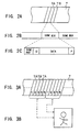
- the recording signal generating circuit 2 divides the shuffled digital signal corresponding to one field into five tracks and as shown in Figs. 2A to 2C outputs the predetermined and plural number of sync blocks by allocating them to the recording tracks TA, TB, ... (Figs. 2A and 2B), respectively. At this time each sync block is output with an error-correcting code P (Fig. 2C).
- the recording signal generating circuit 2 adds a sync pattern at the head of each sync block and then outputs it with a predetermined identification data ID being added thereto.
- two pairs of magnetic heads 7A to 7D of positive and negative azimuth angles are disposed on a rotary drum D with respective angular intervals of 180°.
- one pair of recording heads 7A, 7B of these disposed with an angular interval of 180° are selectively used to form the recording tracks.
- the recording signal S REC is output to the magnetic heads 7A, 7B at timings at which the pair of magnetic heads 7A, 7B scan the magnetic tape T, respectively.
- the video signal corresponding to one field is allocated to five tracks as shown in Figs. 3A and 3B (in this case the video signal corresponding to one frame being allocated to ten tracks).
- the recording signal generating circuit 2 switches the signal processing unit to a unit consisting of a frame.
- data may be more efficiently compressed as a whole in the case of processing in units each consisting of a frame than in the case of processing in units each consisting of a field.
- the recording signal generating circuit 2 divides the digital signal corresponding to one frame into predetermined and plural number of sync blocks and adds sync pattern, identification data ID, parity code P thereto.
- the video tape recorder 1 lowers the running speed of the magnetic tape to 1/2 of that in the case where video signal of the normal television standards is recorded in the standard recording mode.
- the pair of magnetic heads 7A, 7B disposed with an angular interval of 180° of the two pairs of magnetic heads 7A to 7D are selectively used to form recording tracks.
- the video signal corresponding to one frame is allocated to five tracks as shown in Figs. 4A and 4B.
- the signal processing unit of the video signal SV is switched to units each consisting of a field in the recording signal generating circuit 2 and data compression and shuffling are performed by each field unit.
- the recording signal generating circuit 2 divides the data in each field unit into ten sync blocks and adds sync pattern, identification data ID and parity code P thereto.
- the video tape recorder 1 increases the running speed of the magnetic tape to two times that in the case where the video signal of the normal television standards is to be recorded in the standard mode and supplies recording signal S REC to the two pairs of the magnetic heads 7A to 7D to form recording tracks.
- the digital video signal corresponding to one frame is segment-recorded on twenty tracks as shown in Figs. 5A and 5B.
- the signal processing unit is set to units each consisting of a frame to generate recording signal S REC in the recording signal generating circuit 2.
- the magnetic tape running system or the like is controlled in a similar manner as in the case where the video signal of the normal television standards is to be recorded in the standard recording mode, to thereby segment-record the digital video signal corresponding to one frame.
- the track ID is updated by each track successively in the signal processing unit and video ID is updated so that type of digital video signal and recording mode may be identified.
- the video tape recorder 1 switches the contact of the selector 6 to amplify through the amplifier circuit 8 reproducing signal S PB output from the magnetic heads 7A to 7D and then corrects the frequency characteristic thereof through a preprocessing circuit 10.
- the reproducing signal processing circuit 12 receives the reproducing signal S PB processed in the preprocessing circuit 10 to detect a video ID and to process the reproducing signal in accordance with the video ID, and thereby demodulates and outputs the digital video signal SV.
- various video signals may be recorded and reproduced in the form of a digital signal.
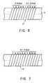
- switching to recording mode may be effected similarly at some midway point P of X+1 field.
- the remaining data of the X+1 field is overwritten and smooth continuation in picture recording becomes impossible.
- the operation mode is switched on the basis of the video ID, the frame ID and the track ID to make possible smooth continuation in picture recording.
- the procedure as shown in Fig. 8 is executed in consecutive taking in picture recording to smoothly perform to the consecutive taking in picture recording.
- step SP1 when processing proceeds from step SP1 to step SP2 where the user the turns on the operation key, command for starting picture recording is read to a system control circuit (not shown) and then processing proceeds to step SP3.
- system control circuit switches the operation as a whole to the operation mode of rewinding to rewind the magnetic tape by an amount of corresponding to several tracks and then proceeds to step SP4 to switch the overall operation mode to the reproducing mode.
- the magnetic tape is rewound to start phase servo of the magnetic tape running system and then switching to picture recording mode is performed.
- step SP5 at which the reproducing signal S PB output from the preprocessing circuit 10 is delivered to a frame ID detecting circuit 20, a track ID detecting circuit 22 and a video ID detecting circuit 24, where the frame ID, the track ID and the video ID are respectively detected.
- a reproducing signal S RF (Fig. 9B) is obtained from the magnetic heads 7A, 7B in synchronization with switching pulse signal SWP (Fig. 9A) of which the signal level is changed over in synchronization with the rotation of the rotary drum D.
- Video ID and track ID are respectively detected from each recording track (Figs. 9C and 9D).
- a symbol SD represents the fact that the video signal of the normal television standards is recorded in the standard recording mode and the consecutive numerals each represents a track ID.
- the video ID detecting circuit 24 Upon detecting the video ID, the video ID detecting circuit 24 outputs the detected result to the track ID detecting circuit 22, and the track ID detecting circuit 22 sequentially detects the track ID on the basis of such detected result.
- a frame pulse FP1 (Fig. 9E) is generated, of which the signal level is changed over in synchronization with the signal processing unit of the video signal at a cycle of five tracks.
- the frame ID detecting circuit 20 detects frame ID to generate a frame pulse FP2 of which the signal level is changed over by each signal processing unit (in ordinary circumstances the signal is as same as signal of FP1 completely).
- An OR circuit 25 receives the first and second frame pulses FP1 and FP2 output from the frame ID detecting circuit 20 and the track ID detecting circuit 22 and, based on these, outputs a switching signal of which the signal level builds-up at a break between signal processing units.
- This OR circuit is used for purpose that obtains frame pulse even if either FP1 or FP2 cannot be detected.
- a flip-flop circuit 26 upon the building-up of the signal level of the switching signal, outputs a switching signal SEL (Fig. 9F) of which the signal level builds-up in synchronization with the building-up of the above switching signal thereby switches the contact of the selecting circuit 6 from the reproducing side to the recording side.
- the frame pulse is generated at step SP6 on the basis of the frame ID, the track ID and the video ID which have been detected at step SP5, so as to switch the operation mode as a whole from the reproducing mode to the recording mode at a break between signal processing units.
- the video tape recorder 1 records the sequentially input video signals SV by converting them into digital signals and then proceeds to step SP7 to terminate this procedure.
- the operation mode as a whole is switched to the reproducing mode to detect frame ID, track ID and video ID and, on the basis of the result of such detection, switching to the recording mode is made at a break between signal processing units.
- recording tracks may be securely formed for each signal processing unit.
- the video signal of the normal television standards recorded in the standard recording mode may be continued smoothly in consecutive picture recording (Fig. 9G).
- the running speed of the magnetic tape is changed in accordance with the recording mode on the basis of the control signal output from the system control circuit.
- a desired video signal is recorded in a desired format on the magnetic tape on which the video signal of the normal television standards has been recorded in the standard recording mode.
- a video ID (Fig. 10C) representing the high definition television standards and the standard recording mode is detected as shown in Figs. 10A to 10E in synchronization with the switching pulse signal SWP and the reproducing signal S RF (Figs. 10A and 10B).
- a track ID (Fig. 10D) of which the value is repeated at a cycle of ten tracks is detected.
- the signal level of the switching signal SEL (Fig. 10E) is caused to build-up at a break between track IDs which corresponds to a break between signal processing units.
- consecutive taking in picture recording may be smoothly performed also for the magnetic tape on which the video signal of the high definition television standards has been recorded in the standard recording mode.
- the operation mode may be changed over in a similar manner at a break between signal processing units in accordance with video ID, track ID and frame ID. Thereby, the consecutive taking in picture recording may be smoothly performed.
- a frame pulse FP2 generated from the frame ID and a frame pulse FP1 generated from the video ID and the track ID are delivered to the OR circuit 25 and, on the basis of the output signal of the OR circuit 25, the operation mode is switched.
- the operation mode is switched.
- the present invention is not limited to this and may be widely applied to cases such as where the forming speed of the recording track is switched to change recording time.
Landscapes
- Engineering & Computer Science (AREA)
- Multimedia (AREA)
- Signal Processing (AREA)
- Television Signal Processing For Recording (AREA)
- Signal Processing For Digital Recording And Reproducing (AREA)
- Digital Magnetic Recording (AREA)
Applications Claiming Priority (2)
| Application Number | Priority Date | Filing Date | Title |
|---|---|---|---|
| JP154400/92 | 1992-05-20 | ||
| JP15440092A JP3287875B2 (ja) | 1992-05-20 | 1992-05-20 | ビデオテープレコーダ |
Publications (3)
| Publication Number | Publication Date |
|---|---|
| EP0570964A2 true EP0570964A2 (fr) | 1993-11-24 |
| EP0570964A3 EP0570964A3 (en) | 1994-08-24 |
| EP0570964B1 EP0570964B1 (fr) | 1998-12-23 |
Family
ID=15583320
Family Applications (1)
| Application Number | Title | Priority Date | Filing Date |
|---|---|---|---|
| EP93108216A Expired - Lifetime EP0570964B1 (fr) | 1992-05-20 | 1993-05-19 | Données d'identification d'un signal vidéo |
Country Status (5)
| Country | Link |
|---|---|
| US (1) | US5410438A (fr) |
| EP (1) | EP0570964B1 (fr) |
| JP (1) | JP3287875B2 (fr) |
| KR (1) | KR100261197B1 (fr) |
| DE (1) | DE69322685T2 (fr) |
Cited By (5)
| Publication number | Priority date | Publication date | Assignee | Title |
|---|---|---|---|---|
| EP0703715A3 (fr) * | 1994-09-26 | 1997-06-25 | Matsushita Electric Industrial Co Ltd | Appareil pour enregistrer des signaux numériques |
| EP0720365A3 (fr) * | 1994-12-26 | 1997-09-10 | Sony Corp | Enregistrement et reproduction de signaux vidéo |
| EP0798721A3 (fr) * | 1996-03-27 | 2000-07-26 | Sony Corporation | Appareil et procédé d'enregistrement de vidéo numérique |
| AU722467B2 (en) * | 1994-12-26 | 2000-08-03 | Sony Corporation | Digital video recorder |
| WO2006049028A1 (fr) | 2004-11-05 | 2006-05-11 | Sony Corporation | Dispositif d’imagerie et méthode de commande d’enregistrement |
Families Citing this family (4)
| Publication number | Priority date | Publication date | Assignee | Title |
|---|---|---|---|---|
| KR100239745B1 (ko) * | 1997-04-25 | 2000-01-15 | 구자홍 | 영상프레임 정위치 녹화방법 |
| US6427048B2 (en) * | 1997-04-28 | 2002-07-30 | Sony Corporation | Apparatus and method for recording, reproducing and displaying a video signal received by a signal receiver |
| KR100280786B1 (ko) * | 1997-12-24 | 2001-02-01 | 윤종용 | 디지털 브이시알의 타임랩스 기록장치 및 기록방법 |
| JP2000100081A (ja) * | 1998-09-25 | 2000-04-07 | Sony Corp | デジタル信号の磁気記録装置及び方法、デジタル信号の磁気再生装置及び方法、並びに、テープ状記録媒体 |
Family Cites Families (19)
| Publication number | Priority date | Publication date | Assignee | Title |
|---|---|---|---|---|
| JPS5968881A (ja) * | 1982-10-13 | 1984-04-18 | Sony Corp | 継ぎ撮り編集装置 |
| JPS59229978A (ja) * | 1983-06-10 | 1984-12-24 | Mitsubishi Electric Corp | 磁気記録方法 |
| JPS6022752A (ja) * | 1983-07-16 | 1985-02-05 | Matsushita Electric Ind Co Ltd | 磁気記録再生装置 |
| JPS6098540A (ja) * | 1983-11-04 | 1985-06-01 | Mitsubishi Electric Corp | 磁気記録再生装置 |
| JPS60179960A (ja) * | 1984-02-24 | 1985-09-13 | Victor Co Of Japan Ltd | 磁気記録再生装置のつなぎ撮り装置 |
| US4825307A (en) * | 1985-09-30 | 1989-04-25 | Canon Kabushiki Kaisha | Information signal recording apparatus |
| JPS62234478A (ja) * | 1986-04-04 | 1987-10-14 | Matsushita Electric Ind Co Ltd | 映像信号の記録再生装置 |
| US4862292A (en) * | 1987-08-26 | 1989-08-29 | Canon Kabushiki Kaisha | Digital information signal recording apparatus |
| JPH0831226B2 (ja) * | 1987-10-13 | 1996-03-27 | 富士写真フイルム株式会社 | つなぎ録画可能なビデオテープ録画装置およびそれを有するビデオカメラ |
| WO1989005028A1 (fr) * | 1987-11-27 | 1989-06-01 | Matsushita Electric Industrial Co., Ltd. | Enregistreur numerique a bande magnetique |
| JPH0632163B2 (ja) * | 1988-08-09 | 1994-04-27 | シャープ株式会社 | 再生装置 |
| JP2584006B2 (ja) * | 1988-10-17 | 1997-02-19 | 株式会社日立製作所 | 磁気記録再生装置 |
| EP0407046B1 (fr) * | 1989-06-16 | 1995-07-26 | Sony Corporation | Procédé et appareil de reproduction d'un signal vidéo numérique |
| JP2822507B2 (ja) * | 1989-11-25 | 1998-11-11 | ソニー株式会社 | ディジタル信号記録装置 |
| JP2638659B2 (ja) * | 1990-03-28 | 1997-08-06 | アイワ株式会社 | ディジタルオーディオテープレコーダ |
| JP2540985B2 (ja) * | 1990-05-29 | 1996-10-09 | 三菱電機株式会社 | デイジタル画面デ―タの記録方式 |
| EP0465110A3 (en) * | 1990-06-27 | 1993-08-11 | Matsushita Electric Industrial Co., Ltd. | Apparatus for record and playback of a digital signal |
| JP2603162B2 (ja) * | 1991-03-04 | 1997-04-23 | シャープ株式会社 | Muse信号デジタル記録・再生装置 |
| US5210658A (en) * | 1992-02-18 | 1993-05-11 | Pressure Products Company, Inc. | Sight glass assembly |
-
1992
- 1992-05-20 JP JP15440092A patent/JP3287875B2/ja not_active Expired - Fee Related
-
1993
- 1993-05-17 US US08/061,732 patent/US5410438A/en not_active Expired - Lifetime
- 1993-05-17 KR KR1019930008383A patent/KR100261197B1/ko not_active Expired - Fee Related
- 1993-05-19 EP EP93108216A patent/EP0570964B1/fr not_active Expired - Lifetime
- 1993-05-19 DE DE69322685T patent/DE69322685T2/de not_active Expired - Fee Related
Cited By (14)
| Publication number | Priority date | Publication date | Assignee | Title |
|---|---|---|---|---|
| EP0989758A1 (fr) * | 1994-09-26 | 2000-03-29 | Matsushita Electric Industrial Co., Ltd. | Appareil pour enregistrer des signaux numériques |
| US6295406B1 (en) | 1994-09-26 | 2001-09-25 | Matsushita Electric Industrial Co., Ltd. | Digital signal recording apparatus for sampling and compressing signals according to various recording modes |
| US5787221A (en) * | 1994-09-26 | 1998-07-28 | Matsushita Electric Industrial Co., Ltd. | Digital signal recording apparatus |
| EP0891104A3 (fr) * | 1994-09-26 | 1999-01-20 | Matsushita Electric Industrial Co., Ltd | Appareil pour enregistrer des signaux numériques |
| EP0891103A3 (fr) * | 1994-09-26 | 1999-01-20 | Matsushita Electric Industrial Co., Ltd | Appareil pour enregistrer des signaux numériques |
| EP0703715A3 (fr) * | 1994-09-26 | 1997-06-25 | Matsushita Electric Industrial Co Ltd | Appareil pour enregistrer des signaux numériques |
| US6215950B1 (en) | 1994-09-26 | 2001-04-10 | Matsushita Electric Industrial Co., Ltd. | Digital signal recording apparatus |
| EP0720365A3 (fr) * | 1994-12-26 | 1997-09-10 | Sony Corp | Enregistrement et reproduction de signaux vidéo |
| AU722467B2 (en) * | 1994-12-26 | 2000-08-03 | Sony Corporation | Digital video recorder |
| US6026212A (en) * | 1994-12-26 | 2000-02-15 | Sony Corporation | Digital video recorder |
| CN1112693C (zh) * | 1996-03-27 | 2003-06-25 | 索尼公司 | 数字图像记录装置和方法 |
| EP0798721A3 (fr) * | 1996-03-27 | 2000-07-26 | Sony Corporation | Appareil et procédé d'enregistrement de vidéo numérique |
| WO2006049028A1 (fr) | 2004-11-05 | 2006-05-11 | Sony Corporation | Dispositif d’imagerie et méthode de commande d’enregistrement |
| EP1696666A4 (fr) * | 2004-11-05 | 2012-02-29 | Sony Corp | Dispositif de fromation d'image et methode de controle d'enregistrement |
Also Published As
| Publication number | Publication date |
|---|---|
| US5410438A (en) | 1995-04-25 |
| KR930023912A (ko) | 1993-12-21 |
| EP0570964A3 (en) | 1994-08-24 |
| JP3287875B2 (ja) | 2002-06-04 |
| DE69322685T2 (de) | 1999-04-29 |
| JPH05325322A (ja) | 1993-12-10 |
| DE69322685D1 (de) | 1999-02-04 |
| KR100261197B1 (ko) | 2000-07-01 |
| EP0570964B1 (fr) | 1998-12-23 |
Similar Documents
| Publication | Publication Date | Title |
|---|---|---|
| US5335116A (en) | Method and apparatus for recording analog video signal in compressed digital format | |
| US4758904A (en) | Apparatus for recording and/or reproducing an additional information signal | |
| JPH0550060B2 (fr) | ||
| KR100196586B1 (ko) | 디지탈 신호 처리 회로 | |
| JPH0375953B2 (fr) | ||
| EP0570964B1 (fr) | Données d'identification d'un signal vidéo | |
| US7027720B2 (en) | Magnetic tape recording apparatus and method, magnetic tape reading apparatus and method, recording medium used therewith, and format for magnetic tape | |
| GB2233489A (en) | Digital video signal recording method and apparatus | |
| JP2958332B2 (ja) | 磁気記録・再生装置 | |
| US5438459A (en) | Method of processing and recording data while reproducing the same and apparatus for the method | |
| JP2778169B2 (ja) | デイジタル信号処理回路 | |
| US5907661A (en) | Video data recording and/or reproducing apparatus | |
| US6263148B1 (en) | Variable-mode information signal reproduction apparatus with tracking control | |
| US5388009A (en) | PCM signal recording method and apparatus capable of adding index code to PCM signal recorded at different transmission rates | |
| US5940575A (en) | Video signal recording apparatus | |
| JP3565433B2 (ja) | ビデオテープレコーダ | |
| EP0729154B1 (fr) | Méthode et appareil d'enregistrement d'une piste de contrôle | |
| JP3594186B2 (ja) | ビデオテープレコーダ | |
| JP2956202B2 (ja) | 記録装置 | |
| JP2714013B2 (ja) | ビデオデータ記録再生装置及び再生装置 | |
| KR100268384B1 (ko) | 영상신호기록방법 | |
| JPH05328274A (ja) | 磁気記録再生装置 | |
| JPS61104303A (ja) | 磁気記録再生装置 | |
| JPH04355273A (ja) | ディジタルデータの記録再生装置 | |
| JPWO1994021082A1 (ja) | 音声信号の再生装置 |
Legal Events
| Date | Code | Title | Description |
|---|---|---|---|
| PUAI | Public reference made under article 153(3) epc to a published international application that has entered the european phase |
Free format text: ORIGINAL CODE: 0009012 |
|
| AK | Designated contracting states |
Kind code of ref document: A2 Designated state(s): DE FR GB NL |
|
| PUAL | Search report despatched |
Free format text: ORIGINAL CODE: 0009013 |
|
| AK | Designated contracting states |
Kind code of ref document: A3 Designated state(s): DE FR GB NL |
|
| 17P | Request for examination filed |
Effective date: 19950131 |
|
| 17Q | First examination report despatched |
Effective date: 19961031 |
|
| APAB | Appeal dossier modified |
Free format text: ORIGINAL CODE: EPIDOS NOAPE |
|
| APAB | Appeal dossier modified |
Free format text: ORIGINAL CODE: EPIDOS NOAPE |
|
| APBJ | Interlocutory revision of appeal recorded |
Free format text: ORIGINAL CODE: EPIDOS IRAPE |
|
| GRAG | Despatch of communication of intention to grant |
Free format text: ORIGINAL CODE: EPIDOS AGRA |
|
| GRAG | Despatch of communication of intention to grant |
Free format text: ORIGINAL CODE: EPIDOS AGRA |
|
| GRAH | Despatch of communication of intention to grant a patent |
Free format text: ORIGINAL CODE: EPIDOS IGRA |
|
| GRAH | Despatch of communication of intention to grant a patent |
Free format text: ORIGINAL CODE: EPIDOS IGRA |
|
| GRAA | (expected) grant |
Free format text: ORIGINAL CODE: 0009210 |
|
| AK | Designated contracting states |
Kind code of ref document: B1 Designated state(s): DE FR GB NL |
|
| REF | Corresponds to: |
Ref document number: 69322685 Country of ref document: DE Date of ref document: 19990204 |
|
| ET | Fr: translation filed | ||
| PLBE | No opposition filed within time limit |
Free format text: ORIGINAL CODE: 0009261 |
|
| 26N | No opposition filed | ||
| REG | Reference to a national code |
Ref country code: GB Ref legal event code: IF02 |
|
| PGFP | Annual fee paid to national office [announced via postgrant information from national office to epo] |
Ref country code: NL Payment date: 20090504 Year of fee payment: 17 |
|
| PGFP | Annual fee paid to national office [announced via postgrant information from national office to epo] |
Ref country code: FR Payment date: 20090515 Year of fee payment: 17 Ref country code: DE Payment date: 20090514 Year of fee payment: 17 |
|
| PGFP | Annual fee paid to national office [announced via postgrant information from national office to epo] |
Ref country code: GB Payment date: 20090513 Year of fee payment: 17 |
|
| REG | Reference to a national code |
Ref country code: NL Ref legal event code: V1 Effective date: 20101201 |
|
| GBPC | Gb: european patent ceased through non-payment of renewal fee |
Effective date: 20100519 |
|
| REG | Reference to a national code |
Ref country code: FR Ref legal event code: ST Effective date: 20110131 |
|
| PG25 | Lapsed in a contracting state [announced via postgrant information from national office to epo] |
Ref country code: NL Free format text: LAPSE BECAUSE OF NON-PAYMENT OF DUE FEES Effective date: 20101201 |
|
| PG25 | Lapsed in a contracting state [announced via postgrant information from national office to epo] |
Ref country code: DE Free format text: LAPSE BECAUSE OF NON-PAYMENT OF DUE FEES Effective date: 20101201 |
|
| PG25 | Lapsed in a contracting state [announced via postgrant information from national office to epo] |
Ref country code: FR Free format text: LAPSE BECAUSE OF NON-PAYMENT OF DUE FEES Effective date: 20100531 |
|
| PG25 | Lapsed in a contracting state [announced via postgrant information from national office to epo] |
Ref country code: GB Free format text: LAPSE BECAUSE OF NON-PAYMENT OF DUE FEES Effective date: 20100519 |