EP0571205A1 - Turbosoufflante régable - Google Patents
Turbosoufflante régable Download PDFInfo
- Publication number
- EP0571205A1 EP0571205A1 EP93303898A EP93303898A EP0571205A1 EP 0571205 A1 EP0571205 A1 EP 0571205A1 EP 93303898 A EP93303898 A EP 93303898A EP 93303898 A EP93303898 A EP 93303898A EP 0571205 A1 EP0571205 A1 EP 0571205A1
- Authority
- EP
- European Patent Office
- Prior art keywords
- housing
- sleeve
- bore
- variable exhaust
- driven turbocharger
- Prior art date
- Legal status (The legal status is an assumption and is not a legal conclusion. Google has not performed a legal analysis and makes no representation as to the accuracy of the status listed.)
- Granted
Links
- 239000007789 gas Substances 0.000 claims description 22
- 238000011144 upstream manufacturing Methods 0.000 claims description 4
- 239000002184 metal Substances 0.000 claims description 3
- 229910052751 metal Inorganic materials 0.000 claims description 3
- 238000003825 pressing Methods 0.000 claims description 3
- 230000000694 effects Effects 0.000 abstract description 3
- 238000010276 construction Methods 0.000 description 3
- PXHVJJICTQNCMI-UHFFFAOYSA-N Nickel Chemical compound [Ni] PXHVJJICTQNCMI-UHFFFAOYSA-N 0.000 description 2
- 230000006698 induction Effects 0.000 description 2
- 229910001220 stainless steel Inorganic materials 0.000 description 2
- 229910000906 Bronze Inorganic materials 0.000 description 1
- 229910000831 Steel Inorganic materials 0.000 description 1
- 239000010974 bronze Substances 0.000 description 1
- 238000005266 casting Methods 0.000 description 1
- 229910017052 cobalt Inorganic materials 0.000 description 1
- 239000010941 cobalt Substances 0.000 description 1
- GUTLYIVDDKVIGB-UHFFFAOYSA-N cobalt atom Chemical compound [Co] GUTLYIVDDKVIGB-UHFFFAOYSA-N 0.000 description 1
- 238000002485 combustion reaction Methods 0.000 description 1
- 230000008602 contraction Effects 0.000 description 1
- 230000008878 coupling Effects 0.000 description 1
- 238000010168 coupling process Methods 0.000 description 1
- 238000005859 coupling reaction Methods 0.000 description 1
- 238000005553 drilling Methods 0.000 description 1
- 239000000314 lubricant Substances 0.000 description 1
- 239000000463 material Substances 0.000 description 1
- 239000000203 mixture Substances 0.000 description 1
- 229910052759 nickel Inorganic materials 0.000 description 1
- 230000002093 peripheral effect Effects 0.000 description 1
- 239000010935 stainless steel Substances 0.000 description 1
- 239000010959 steel Substances 0.000 description 1
- 238000005382 thermal cycling Methods 0.000 description 1
Images


Classifications
-
- F—MECHANICAL ENGINEERING; LIGHTING; HEATING; WEAPONS; BLASTING
- F01—MACHINES OR ENGINES IN GENERAL; ENGINE PLANTS IN GENERAL; STEAM ENGINES
- F01D—NON-POSITIVE DISPLACEMENT MACHINES OR ENGINES, e.g. STEAM TURBINES
- F01D17/00—Regulating or controlling by varying flow
- F01D17/10—Final actuators
- F01D17/12—Final actuators arranged in stator parts
- F01D17/14—Final actuators arranged in stator parts varying effective cross-sectional area of nozzles or guide conduits
- F01D17/141—Final actuators arranged in stator parts varying effective cross-sectional area of nozzles or guide conduits by means of shiftable members or valves obturating part of the flow path
- F01D17/143—Final actuators arranged in stator parts varying effective cross-sectional area of nozzles or guide conduits by means of shiftable members or valves obturating part of the flow path the shiftable member being a wall, or part thereof of a radial diffuser
Definitions
- This invention relates to variable exhaust driven turbochargers particularly of a type which comprises a turbine housing within which a turbine wheel is rotatably supported to be driven by engine exhaust gas impinging thereon, to drive a compressor impeller.
- turbochargers which include a turbine wheel rotatably supported in a turbine housing to be rotatable by engine exhaust gas ducted thereto via an annular nozzle.
- Such nozzle has included vanes other than radially angled to provide advantageous gas flow geometry and the effective axial nozzle passage width has been proposed to be variable by means which moves the vanes axially or alternatively by means which moves a heat shroud over the vanes or alternatively varies the angle of the vanes.
- Such turbochargers have usually comprised a central housing carrying bearing means for a common shaft which supports the turbine wheel in its housing at one end and supports the compressor impeller in its compressor housing at the other end.
- the central housing has also contained means for movably supporting the vanes or the heat shroud and actuating means for moving same to vary the turbine nozzle geometry.
- the object of the present invention is to provide a variable exhaust-driven turbocharger affording simpler construction and control actuation than hitherto, particularly for the centre housing and to give improved gas flow.
- a variable exhaust driven turbocharger comprising a compressor impeller mounted on a shaft rotatable in a compressor housing said shaft being driveably connected to a turbine wheel rotatable in a turbine housing, said turbine housing having an inlet nozzle for receiving exhaust gases from an engine and being shaped to conduct such gases to impinge upstream edges of blades of said turbine wheel, said nozzle having axially spaced side walls extending about said upstream edges of the turbine wheel and having axially extending spaced and angled vanes traversing the space defined between the side walls and wherein one said side wall is carried by an axially movable sleeve slideably carried in a bore of the housing downstream of the turbine wheel and said bore having at least one elongate aperture via which actuating means communicates with the sleeve from outside the housing to axially move the sleeve to vary the geometry of said nozzle.
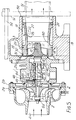
- the exhaust-driven turbocharger comprises a housing assembly including a centre-housing 1 which contains a main bearing as further described later. Attached to the housing at the left and right hand ends as shown in Fig. 1 there is a two-part compressor housing 2 and a turbine housing 3 respectively.
- the compressor housing is formed with an atmospheric air inlet duct 4 communicating in an axial direction with the outer end of a compressor impeller 5 having a shaped hub 6 fixedly attached to a turbocharger main shaft and blades 7, of generally known form, shaped to closely match the interior of housing. Rotation causes induced air at duct 4 to be compressed in a reducing-section scroll-shaped cavity formed in part 2a to emerge at an elevated pressure at a delivery port 9 (Fig. 2).
- the compressor impeller 5 is driven via the turbocharger main shaft 8 by an exhaust-gas-driven turbine wheel 10 formed integrally with the shaft 8.
- the turbine wheel comprises a shaped hub 11 and turbine blades 12 carried thereby.
- the blades 12 have a generally cylindrical gas receiving edge profile 13 and are shaped to receive exhaust gas radially inwards via a scroll-shaped turbine chamber 14 from an engine manifold mounting flange 15, the exhaust gas being emitted axially from the turbine wheel 10 into the exhaust pipe 51.
- the gas flow from the scroll-shaped chamber 14 is via a variable geometry annular turbine nozzle 16, the nozzle 16 being defined in an annular region of the turbine housing which is traversed axially by shaped and angled spaced nozzle vanes 17. These vanes are each mutually equally spaced and angled away from respective radii and extend across an axially variable annular space defined between the annular side walls of the annular nozzle. The nozzle geometry is therefore variable by adjusting the spacing between these annular side walls. In the present example there are twelve such vanes 17 having cross sectional shape similar to the vanes 57 referred to later with reference to Figs. 6a and 6b.
- vanes 17 are carried by one wall, namely the inner end wall 18 of a generally cylindrical sleeve member 20 which is axially slideable within the bore 19 of the turbine housing part 3.
- the other side wall of the variable geometry nozzle is provided by a fixed sheet-metal heat shroud 21 which is formed of a generally dish shape and has equally spaced and angled slots 22 to closely receive the angled and axially moving vanes 17.
- the heat shroud 21 is provided with a further annular dish shaped part 21a, the shroud parts 21 and 21a being mutually sealed together to form a gas-tight annular enclosure the only gas connection to which is via any clearance around vanes 17 in slots 22.
- the length of the turbine nozzle is thereby increased by rightward movement of the member 20 towards a position shown in broken lines in Fig. 1.
- the cylindrical member 20 is provided with spaced peripheral bearing rings 23, 24 of suitably compatible material with bore 19 and located in annular grooves at the vicinities of the respective ends and these bearing rings define a closed annular region 25 between member 20 and the surrounding bore.
- the member 20 is provided with radially inward drillings 26 to retainably receive two press-fitted control pins 29, which are able to project through the turbine housing 3 via two diametrically opposed and axially elongate apertures such as 27, for engagement with a control yoke 28.
- the apertures 27 are always between the bearing rings 23 and 24 whereby the pins and apertures are effectively isolated from the hot gases.
- the yoke 28 is generally annular in shape and of such relatively large internal diameter as to freely pass around the external diameter of the outlet duct of the turbine housing 3, whilst also permitting tilting movement about a pivot pin 31 of a projection 32 at one end supported by the housing at 39.
- the diametrically opposed other end 33 of yoke 28 has a further projection 33, making pivotal connection to an actuator rod 35 via a pivot pin 34.
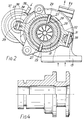
- An actuator rod 35 is provided which comprises an actuator output rod of a pneumatic actuator 36 (seen in end view of Fig. 2) carried on an integral bracket 37 of the turbocharger housing.
- the output rod 35 lies approximately parallel to the axis of the turbocharger shaft 8 and typically the output rod is movable by an internal diaphragm (not shown) in response to super atmospheric air pressure applied to an input pipe 38.
- This the mechanism operates in the sense that increased control pressure at pipe 38 of the pneumatic actuator 36 causes the output rod to move axially outwards of the actuator (Fig. 2) pivoting the yoke 28 about pivot pin 31.
- Such movement carries pins 27 and therefore sleeve 201 in the same direction in bore 19 to increase the length of the space between the annular side walls 18, 21 of the turbine nozzle.
- the turbine housing 3 and the turbine 10 are manufactured as castings of castable stainless steel, typically being a mixture of ostenitic and ferritic stainless steels chosen for combined properties which are suitable for such turbocharger application.
- the turbine wheel 10 is a high cobalt high nickel steel which has high centrifugal stress properties at the elevated temperatures which prevail and it also expands less than the surrounding sleeve 20.
- the portion of that housing which contains the bore 19 has substantially uniform annular section over a major part of its length, although the thickness progressively slightly reduces in the downstream direction towards an annular end surface 50 which abuts an exhaust pipe coupling flange such as shown in broken lines at 51.
- the flange 51 is bolted axially via bolts, such as 52 to three (not shown) projections from the centre housing spaced around the turbine housing to allow free flow of air around the latter and to direct the induced stresses due to the exhaust pipe into the housing 3, away from the central bore 19.
- the housing 1 is provided with a bore 40 which receives a phosphor-bronze bearing bush 41 within which the main shaft 8 rotates with predetermined diametral clearance at respective bearing portions 42 and 43 which are fed with lubricant under pressure from a port 44 via passages 45 and 46.
- the portion of the housing which carries the main shaft is also surrounded by a draining region 47 which oil emanating from the pressurised bearing portions 42 and 43 is free to drain away back to the oil sum (not shown) for recirculation.
- Assembly of the turbocharger is as follows.
- the turbine wheel with its integral main shaft is first assembled to the centre housing together with the bearing bush 41 and the heat shroud 21.
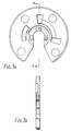
- a thrust bearing 48 seen on enlarged scale plan and section AA views in Figs. 3a and 3b including suitable oil ways, and a cooperating collar 49 to be seen in further enlarged part-sectional view in Fig. 4, are also then placed in position in the housing and located on the shaft before bolting the plate 2b onto the centre housing whilst retaining the shaft 8 in position.
- the heat shroud 21,22 is then positioned.
- the compressor impeller 5 is then placed in position and locked to the shaft by means of a nut 6a before attaching the induction portion 2b of the compressor housing.
- the turbine housing is then assembled with its sleeve member 20, the heat shroud 21 being in position on the centre housing to receive the vanes 17 and the pins 29 then being inserted by press fitting and housing 3 is finally attached to the centre housing by means of three mounting studs (not shown).
- the yoke 28 is then positioned by means of pin 31 and 29 are inserted through clearance holes in yoke 28 and slots 27. Pins 29 being a press fit in the diametral holes in sleeve 20 are self retaining. Pivot pin 34 is then inserted to connect and complete the actuator mechanism.
- the yoke 28 of Fig. 2 may be comprised of two metal pressings between which the actuating pins 29 are trapped when the two pressings are brought together and located on pins 31 and 34.
- variable nozzle turbocharger In operation of the variable nozzle turbocharger, when mounted to an internal combustion engine, exhaust gases flow from the engine exhaust manifold via flange 15 into the larger end of the scroll-formed turbine chamber 14 to impinge on the turbine wheel 10, 12 via the annular nozzle formed between walls 18 and 21.
- the gas flow through the nozzle is aerodynamically ordered via the axially extending and angled vanes 17, resulting in rotation of the turbine wheel and the compressor impeller 5, 6 to increase the pressure induced thereby with the induction manifold of the engine. Since the vanes 17 project with a close fit through the slots 22 into an enclosed annular chamber, loss of efficiency due to gas flow through slots 22 is minimised.
- the pneumatic actuator 36 is supplied with a pressure signal at 38 which in general varies with the loading on the engine in a sense to move the sleeve 20 in a rightward direction as seen in Fig. 1 to increase the effective length of the variable geometry nozzle for increased engine loading.
- the turbocharger control programme is thereby designable to enable desired resultant compressor air pressure at 38 to be maintained substantially independently of engine speed.
- variable input nozzles have twelve angled vanes, a larger number of such vanes may advantageously be employed for an optimal gas flow configuration.
Landscapes
- Engineering & Computer Science (AREA)
- Mechanical Engineering (AREA)
- General Engineering & Computer Science (AREA)
- Supercharger (AREA)
- Control Of Turbines (AREA)
Applications Claiming Priority (4)
| Application Number | Priority Date | Filing Date | Title |
|---|---|---|---|
| GB929210892A GB9210892D0 (en) | 1992-05-21 | 1992-05-21 | Variable exhaust driven turbochargers |
| GB9210892 | 1992-05-21 | ||
| GB929214085A GB9214085D0 (en) | 1992-07-02 | 1992-07-02 | Variable exhaust driven turbochargers |
| GB9214085 | 1992-07-02 |
Publications (2)
| Publication Number | Publication Date |
|---|---|
| EP0571205A1 true EP0571205A1 (fr) | 1993-11-24 |
| EP0571205B1 EP0571205B1 (fr) | 1997-03-05 |
Family
ID=26300914
Family Applications (1)
| Application Number | Title | Priority Date | Filing Date |
|---|---|---|---|
| EP93303898A Expired - Lifetime EP0571205B1 (fr) | 1992-05-21 | 1993-05-19 | Turbosoufflante réglable |
Country Status (4)
| Country | Link |
|---|---|
| US (1) | US5441383A (fr) |
| EP (1) | EP0571205B1 (fr) |
| JP (1) | JPH0650164A (fr) |
| DE (1) | DE69308377T2 (fr) |
Cited By (16)
| Publication number | Priority date | Publication date | Assignee | Title |
|---|---|---|---|---|
| DE19543190A1 (de) * | 1995-11-20 | 1997-05-28 | Daimler Benz Ag | Motorbremsverfahren für eine aufgeladene Brennkraftmaschine |
| WO1998046862A1 (fr) * | 1997-04-12 | 1998-10-22 | Holset Engineering Co. Ltd. | Mecanisme de commande pour deflecteur coulissant |
| EP0884453A1 (fr) * | 1997-06-10 | 1998-12-16 | Holset Engineering Company Limited | Turbine à géométrie variable |
| WO2002006636A1 (fr) * | 2000-07-19 | 2002-01-24 | Honeywell Garrett Sa | Turbocompresseur a ailettes coulissantes avec ailettes graduees |
| WO2003023194A1 (fr) * | 2001-09-10 | 2003-03-20 | Malcolm George Leavesley | Turbocompresseur |
| RU2216647C2 (ru) * | 2001-12-27 | 2003-11-20 | ОАО "КАМАЗ-Дизель" | Турбокомпрессор |
| WO2004022926A1 (fr) * | 2002-09-05 | 2004-03-18 | Honeywell International Inc. | Turbocompresseur comprenant un dispositif de tuyere variable |
| WO2004022924A1 (fr) * | 2002-09-06 | 2004-03-18 | Honeywell Garrett Sa | Turbocompresseur a aubes coulissantes a autoregulation |
| WO2004074642A1 (fr) * | 2003-02-19 | 2004-09-02 | Honeywell International Inc. | Turbine a gorge variable |
| WO2006133838A1 (fr) * | 2005-06-11 | 2006-12-21 | Daimlerchrysler Ag | Turbine a gaz d'echappement d'un turbocompresseur a gaz d'echappement |
| EP1925784A1 (fr) * | 2002-09-05 | 2008-05-28 | Honeywell International Inc. | Turbocompresseur comprenant un dispositif doté d'une buse variable |
| RU2339850C1 (ru) * | 2007-01-24 | 2008-11-27 | Федеральное государственное унитарное предприятие "Воронежский механический завод" | Турбокомпрессор |
| GB2473274A (en) * | 2009-09-08 | 2011-03-09 | Cummins Turbo Tech Ltd | Variable geometry turbine |
| RU2467208C1 (ru) * | 2011-06-06 | 2012-11-20 | Николай Александрович Вахрамов | Турбокомпрессор |
| RU2469213C1 (ru) * | 2011-06-06 | 2012-12-10 | Николай Александрович Вахрамов | Турбокомпрессор |
| DE102019000252A1 (de) | 2019-01-13 | 2019-03-07 | Siegfried Sumser | Axialschieber-Turbine mit axial verschiebbarem Leitgitterträger |
Families Citing this family (39)
| Publication number | Priority date | Publication date | Assignee | Title |
|---|---|---|---|---|
| EP0654587B1 (fr) * | 1993-11-19 | 1999-01-20 | Holset Engineering Company Limited | Turbine avec entrée à géométrie variable |
| DE19615237C2 (de) * | 1996-04-18 | 1999-10-28 | Daimler Chrysler Ag | Abgasturbolader für eine Brennkraftmaschine |
| DE19651498C1 (de) * | 1996-12-11 | 1998-04-16 | Daimler Benz Ag | Abgasturboladerturbine für eine Brennkraftmaschine |
| DE19816645B4 (de) * | 1998-04-15 | 2005-12-01 | Daimlerchrysler Ag | Abgasturboladerturbine |
| JP2003535248A (ja) | 2000-01-14 | 2003-11-25 | ハネウェル ガレット エス アー | 空力表面と遮熱板を結合して有するスライディングブレードおよび不連結シャフトアクチュエータ装置を備えるターボチャージャ |
| KR100669487B1 (ko) | 2000-07-19 | 2007-01-16 | 허니웰 인터내셔날 인코포레이티드 | 가변 형상 터보차져 |
| GB0025244D0 (en) | 2000-10-12 | 2000-11-29 | Holset Engineering Co | Turbine |
| CN100340742C (zh) * | 2000-11-30 | 2007-10-03 | 霍尼韦尔加勒特股份有限公司 | 带有滑动活塞的可变形状涡轮增压器 |
| US6767185B2 (en) * | 2002-10-11 | 2004-07-27 | Honeywell International Inc. | Turbine efficiency tailoring |
| GB0227473D0 (en) * | 2002-11-25 | 2002-12-31 | Leavesley Malcolm G | Variable turbocharger apparatus with bypass apertures |
| FR2860185B1 (fr) * | 2003-09-30 | 2007-06-29 | Johnson Controls Tech Co | Dispositif de detection de fuite et de sous-gonflage des pneumatiques des roues de vehicules automobiles |
| AU2003278524A1 (en) * | 2003-10-24 | 2005-05-11 | Honeywell International Inc | Sector-divided turbine assembly with axial piston variable-geometry mechanism |
| WO2005106210A1 (fr) * | 2004-05-03 | 2005-11-10 | Honeywell International Inc. | Turbocompresseur a gaz d'echappement dote d'une bague coulissante reglable |
| KR100883426B1 (ko) * | 2005-03-05 | 2009-02-13 | 허니웰 인터내셔널 인코포레이티드 | 가변 노즐장치를 구비한 터보 차저 |
| US8047772B2 (en) * | 2005-03-30 | 2011-11-01 | Honeywell International Inc. | Variable geometry turbine for a turbocharger and method of controlling the turbine |
| US8037684B2 (en) * | 2005-04-04 | 2011-10-18 | Honeywell International Inc. | Variable flow turbocharger |
| US7631497B2 (en) * | 2005-04-21 | 2009-12-15 | Borgwarner Inc. | Turbine heat shield with ribs |
| US7278820B2 (en) * | 2005-10-04 | 2007-10-09 | Siemens Power Generation, Inc. | Ring seal system with reduced cooling requirements |
| WO2007058649A1 (fr) * | 2005-11-16 | 2007-05-24 | Honeywell International, Inc. | Turbocompresseur a buse a palettes a deux etages |
| EP1816317B1 (fr) * | 2006-02-02 | 2013-06-12 | IHI Corporation | Turbocompresseur à géométrie variable |
| US8112995B2 (en) * | 2006-06-19 | 2012-02-14 | Turbo Energy Limited | Turbocharger with variable turbine geometry |
| JP5238711B2 (ja) * | 2006-11-01 | 2013-07-17 | ボーグワーナー インコーポレーテッド | タービン防熱材組立体 |
| US20080271449A1 (en) * | 2007-05-01 | 2008-11-06 | Quentin Roberts | Turbocharger with sliding piston, having overlapping fixed and moving vanes |
| US7762067B2 (en) * | 2007-08-21 | 2010-07-27 | Honeywell International, Inc. | Turbocharger with sliding piston assembly |
| GB2462115A (en) * | 2008-07-25 | 2010-01-27 | Cummins Turbo Tech Ltd | Variable geometry turbine |
| EP2396519B1 (fr) * | 2009-01-20 | 2017-07-12 | Williams International Co., L.L.C. | Noyau de turbocompresseur avec cartouche |
| DE102009057664A1 (de) * | 2009-12-09 | 2011-06-16 | Ihi Charging Systems International Gmbh | Verstelleinrichtung für eine Aufladeeinrichtung, insbesondere für einen Abgasturbolader |
| DE102009058411A1 (de) * | 2009-12-16 | 2011-06-22 | BorgWarner Inc., Mich. | Abgasturbolader |
| US20110173973A1 (en) * | 2010-01-20 | 2011-07-21 | International Engine Intellectrual Property Company, LLC | Turbine inlet flow modulator |
| JP5473762B2 (ja) * | 2010-04-30 | 2014-04-16 | 三菱重工業株式会社 | 可変容量タービンおよびこれを備えた可変容量ターボチャージャ |
| JP2013535615A (ja) * | 2010-08-05 | 2013-09-12 | ボーグワーナー インコーポレーテッド | 排気ガスターボチャージャ |
| WO2012170754A1 (fr) * | 2011-06-10 | 2012-12-13 | Borgwarner Inc. | Turbocompresseur comprenant une turbine à double flux |
| US20160003096A1 (en) * | 2013-02-19 | 2016-01-07 | Borgwarner Inc | Turbocharger internal turbine heat shield having axial flow turning vanes |
| CN106460520B (zh) * | 2014-05-20 | 2019-06-07 | 博格华纳公司 | 废气涡轮增压器 |
| US9689397B2 (en) | 2014-06-13 | 2017-06-27 | GM Global Technology Operations LLC | Turbine outlet diffuser |
| EP3267010B1 (fr) * | 2015-03-05 | 2019-05-08 | Mitsubishi Heavy Industries Engine & Turbocharger, Ltd. | Turbocompresseur |
| US10056702B2 (en) | 2015-11-04 | 2018-08-21 | Gentherm, Inc. | Crimp connection for mesh shielding material used in steering wheel with capacitive sensing |
| CN105569747B (zh) * | 2016-03-21 | 2018-02-06 | 付鹏程 | 可变截面的涡轮增压器 |
| DE102017108057A1 (de) * | 2017-04-13 | 2018-10-18 | Abb Turbo Systems Ag | Düsenring für einen abgasturbolader |
Citations (9)
| Publication number | Priority date | Publication date | Assignee | Title |
|---|---|---|---|---|
| US2996996A (en) * | 1958-01-20 | 1961-08-22 | Sulzer Ag | Radial diffuser for a radial turbomachine |
| US3079127A (en) * | 1956-11-23 | 1963-02-26 | Garrett Corp | Temperature responsive variable means for controlling flow in turbomachines |
| DE1264675B (de) * | 1964-05-11 | 1968-03-28 | Sulzer Ag | Vorrichtung zum Verstellen der Stroemungsquerschnitte von Diffusoren bei einer Turbomaschine |
| GB1138941A (en) * | 1965-01-15 | 1969-01-01 | Stuart Swinford Wilson | Improvements in and relating to radial flow turbines |
| FR2359973A1 (fr) * | 1976-07-27 | 1978-02-24 | Kloeckner Humboldt Deutz Ag | Moteur a explosion muni d'un turbocompresseur de suralimentation a gaz d'echappement |
| US4403914A (en) * | 1981-07-13 | 1983-09-13 | Teledyne Industries, Inc. | Variable geometry device for turbomachinery |
| CH668455A5 (en) * | 1984-06-29 | 1988-12-30 | Bbc Brown Boveri & Cie | Exhaust turbocharger with adjustable inlet - has blade ring on sleeve sliding on cylindrical surface |
| EP0342889A1 (fr) * | 1988-05-17 | 1989-11-23 | Holset Engineering Company Limited | Turbine avec stator à géométrie variable |
| WO1989011583A1 (fr) * | 1988-05-27 | 1989-11-30 | Malcolm George Leavesley | Dispositif a suralimentation |
-
1993
- 1993-05-19 EP EP93303898A patent/EP0571205B1/fr not_active Expired - Lifetime
- 1993-05-19 US US08/064,534 patent/US5441383A/en not_active Expired - Lifetime
- 1993-05-19 DE DE69308377T patent/DE69308377T2/de not_active Expired - Lifetime
- 1993-05-20 JP JP5118475A patent/JPH0650164A/ja active Pending
Patent Citations (9)
| Publication number | Priority date | Publication date | Assignee | Title |
|---|---|---|---|---|
| US3079127A (en) * | 1956-11-23 | 1963-02-26 | Garrett Corp | Temperature responsive variable means for controlling flow in turbomachines |
| US2996996A (en) * | 1958-01-20 | 1961-08-22 | Sulzer Ag | Radial diffuser for a radial turbomachine |
| DE1264675B (de) * | 1964-05-11 | 1968-03-28 | Sulzer Ag | Vorrichtung zum Verstellen der Stroemungsquerschnitte von Diffusoren bei einer Turbomaschine |
| GB1138941A (en) * | 1965-01-15 | 1969-01-01 | Stuart Swinford Wilson | Improvements in and relating to radial flow turbines |
| FR2359973A1 (fr) * | 1976-07-27 | 1978-02-24 | Kloeckner Humboldt Deutz Ag | Moteur a explosion muni d'un turbocompresseur de suralimentation a gaz d'echappement |
| US4403914A (en) * | 1981-07-13 | 1983-09-13 | Teledyne Industries, Inc. | Variable geometry device for turbomachinery |
| CH668455A5 (en) * | 1984-06-29 | 1988-12-30 | Bbc Brown Boveri & Cie | Exhaust turbocharger with adjustable inlet - has blade ring on sleeve sliding on cylindrical surface |
| EP0342889A1 (fr) * | 1988-05-17 | 1989-11-23 | Holset Engineering Company Limited | Turbine avec stator à géométrie variable |
| WO1989011583A1 (fr) * | 1988-05-27 | 1989-11-30 | Malcolm George Leavesley | Dispositif a suralimentation |
Cited By (26)
| Publication number | Priority date | Publication date | Assignee | Title |
|---|---|---|---|---|
| DE19543190A1 (de) * | 1995-11-20 | 1997-05-28 | Daimler Benz Ag | Motorbremsverfahren für eine aufgeladene Brennkraftmaschine |
| DE19543190C2 (de) * | 1995-11-20 | 1998-01-29 | Daimler Benz Ag | Motorbremse für eine aufgeladene Brennkraftmaschine |
| WO1998046862A1 (fr) * | 1997-04-12 | 1998-10-22 | Holset Engineering Co. Ltd. | Mecanisme de commande pour deflecteur coulissant |
| CN1092751C (zh) * | 1997-04-12 | 2002-10-16 | 奥尔塞特工程有限公司 | 连杆机构 |
| EP0884453A1 (fr) * | 1997-06-10 | 1998-12-16 | Holset Engineering Company Limited | Turbine à géométrie variable |
| WO2002006636A1 (fr) * | 2000-07-19 | 2002-01-24 | Honeywell Garrett Sa | Turbocompresseur a ailettes coulissantes avec ailettes graduees |
| US7097432B1 (en) | 2000-07-19 | 2006-08-29 | Honeywell International, Inc. | Sliding vane turbocharger with graduated vanes |
| GB2394014B (en) * | 2001-09-10 | 2005-12-14 | Malcolm George Leavesley | Turbocharger apparatus |
| US6928816B2 (en) | 2001-09-10 | 2005-08-16 | Malcolm George Leavesley | Turbocharger apparatus |
| WO2003023194A1 (fr) * | 2001-09-10 | 2003-03-20 | Malcolm George Leavesley | Turbocompresseur |
| RU2216647C2 (ru) * | 2001-12-27 | 2003-11-20 | ОАО "КАМАЗ-Дизель" | Турбокомпрессор |
| EP1925784A1 (fr) * | 2002-09-05 | 2008-05-28 | Honeywell International Inc. | Turbocompresseur comprenant un dispositif doté d'une buse variable |
| WO2004022926A1 (fr) * | 2002-09-05 | 2004-03-18 | Honeywell International Inc. | Turbocompresseur comprenant un dispositif de tuyere variable |
| CN1333154C (zh) * | 2002-09-05 | 2007-08-22 | 霍尼韦尔国际公司 | 包括可调喷管机构的涡轮增压器 |
| WO2004022924A1 (fr) * | 2002-09-06 | 2004-03-18 | Honeywell Garrett Sa | Turbocompresseur a aubes coulissantes a autoregulation |
| WO2004074642A1 (fr) * | 2003-02-19 | 2004-09-02 | Honeywell International Inc. | Turbine a gorge variable |
| CN101218415B (zh) * | 2005-06-11 | 2010-06-23 | 戴姆勒股份公司 | 废气涡轮增压器中的废气涡轮机 |
| WO2006133838A1 (fr) * | 2005-06-11 | 2006-12-21 | Daimlerchrysler Ag | Turbine a gaz d'echappement d'un turbocompresseur a gaz d'echappement |
| US8186943B2 (en) | 2005-06-11 | 2012-05-29 | Daimler Ag | Exhaust-gas turbine in an exhaust-gas turbocharger |
| RU2339850C1 (ru) * | 2007-01-24 | 2008-11-27 | Федеральное государственное унитарное предприятие "Воронежский механический завод" | Турбокомпрессор |
| GB2473274A (en) * | 2009-09-08 | 2011-03-09 | Cummins Turbo Tech Ltd | Variable geometry turbine |
| US8696307B2 (en) | 2009-09-08 | 2014-04-15 | Cummins Ltd. | Variable geometry turbine |
| GB2473274B (en) * | 2009-09-08 | 2016-01-06 | Cummins Turbo Tech Ltd | Variable geometry turbine |
| RU2467208C1 (ru) * | 2011-06-06 | 2012-11-20 | Николай Александрович Вахрамов | Турбокомпрессор |
| RU2469213C1 (ru) * | 2011-06-06 | 2012-12-10 | Николай Александрович Вахрамов | Турбокомпрессор |
| DE102019000252A1 (de) | 2019-01-13 | 2019-03-07 | Siegfried Sumser | Axialschieber-Turbine mit axial verschiebbarem Leitgitterträger |
Also Published As
| Publication number | Publication date |
|---|---|
| EP0571205B1 (fr) | 1997-03-05 |
| DE69308377D1 (de) | 1997-04-10 |
| DE69308377T2 (de) | 1997-06-19 |
| JPH0650164A (ja) | 1994-02-22 |
| US5441383A (en) | 1995-08-15 |
Similar Documents
| Publication | Publication Date | Title |
|---|---|---|
| US5441383A (en) | Variable exhaust driven turbochargers | |
| EP1009918B1 (fr) | Turbosoufflante double essieu a tuyere variable et pression autoregularisee | |
| JP4181121B2 (ja) | 可変ノズル装置を備えたターボ過給機 | |
| US6951450B1 (en) | Variable geometry turbocharger | |
| US7024855B2 (en) | Variable geometry turbocharger with sliding piston | |
| US5518365A (en) | Radial-flow exhaust gas turbocharger turbine with adjustable guide vanes | |
| US7001142B2 (en) | Turbocharger for vehicle with improved suspension of the actuating mechanism for variable nozzles | |
| KR100643093B1 (ko) | 스텝 베인을 가진 슬라이드 베인 터보차저 | |
| US4214852A (en) | Variable turbine vane assembly | |
| EP3282097B1 (fr) | Turbine à buse variable doté de moyens de positionnement radial de cartouche à buse variable | |
| EP1668225B1 (fr) | Turbocompresseur a geometrie variable | |
| JP2017515051A (ja) | 可変ジオメトリタービンアセンブリ | |
| KR20090035606A (ko) | 조정 가능한 안내 베인의 시일링 수단 | |
| US5498128A (en) | Radial-flow exhaust gas turbocharger turbine with adjustable guide vanes | |
| KR102360364B1 (ko) | 터보 기계용 베인 구조체 | |
| US12467381B2 (en) | Variable geometry turbine | |
| EP1743088B1 (fr) | Turbine d'un turbocompresseur | |
| EP1856431B1 (fr) | Detail de forme d' un piston permettant d' eviter le coincement a l' interieur d' un alesage tordu | |
| WO2024157030A1 (fr) | Turbine à géométrie variable | |
| CN110195618A (zh) | 可变几何涡轮机 | |
| KR20050098827A (ko) | 가변 노즐장치를 구비한 터보 차저 |
Legal Events
| Date | Code | Title | Description |
|---|---|---|---|
| PUAI | Public reference made under article 153(3) epc to a published international application that has entered the european phase |
Free format text: ORIGINAL CODE: 0009012 |
|
| AK | Designated contracting states |
Kind code of ref document: A1 Designated state(s): DE ES FR GB IT NL SE |
|
| 17P | Request for examination filed |
Effective date: 19940317 |
|
| 17Q | First examination report despatched |
Effective date: 19950505 |
|
| GRAG | Despatch of communication of intention to grant |
Free format text: ORIGINAL CODE: EPIDOS AGRA |
|
| GRAH | Despatch of communication of intention to grant a patent |
Free format text: ORIGINAL CODE: EPIDOS IGRA |
|
| GRAH | Despatch of communication of intention to grant a patent |
Free format text: ORIGINAL CODE: EPIDOS IGRA |
|
| GRAA | (expected) grant |
Free format text: ORIGINAL CODE: 0009210 |
|
| AK | Designated contracting states |
Kind code of ref document: B1 Designated state(s): DE ES FR GB IT NL SE |
|
| PG25 | Lapsed in a contracting state [announced via postgrant information from national office to epo] |
Ref country code: NL Free format text: LAPSE BECAUSE OF FAILURE TO SUBMIT A TRANSLATION OF THE DESCRIPTION OR TO PAY THE FEE WITHIN THE PRESCRIBED TIME-LIMIT Effective date: 19970305 Ref country code: ES Free format text: THE PATENT HAS BEEN ANNULLED BY A DECISION OF A NATIONAL AUTHORITY Effective date: 19970305 |
|
| ITF | It: translation for a ep patent filed | ||
| ET | Fr: translation filed | ||
| REF | Corresponds to: |
Ref document number: 69308377 Country of ref document: DE Date of ref document: 19970410 |
|
| PG25 | Lapsed in a contracting state [announced via postgrant information from national office to epo] |
Ref country code: SE Effective date: 19970605 |
|
| NLV1 | Nl: lapsed or annulled due to failure to fulfill the requirements of art. 29p and 29m of the patents act | ||
| PLBE | No opposition filed within time limit |
Free format text: ORIGINAL CODE: 0009261 |
|
| STAA | Information on the status of an ep patent application or granted ep patent |
Free format text: STATUS: NO OPPOSITION FILED WITHIN TIME LIMIT |
|
| 26N | No opposition filed | ||
| REG | Reference to a national code |
Ref country code: GB Ref legal event code: IF02 |
|
| PGFP | Annual fee paid to national office [announced via postgrant information from national office to epo] |
Ref country code: FR Payment date: 20050517 Year of fee payment: 13 |
|
| AK | Designated contracting states |
Kind code of ref document: A1 Designated state(s): AT BE BG CH CY CZ DE DK EE ES FI FR GB GR HU IE IT LI LU MC NL PL PT RO SE SI SK TR |
|
| AX | Request for extension of the european patent |
Extension state: AL LT LV MK |
|
| 18W | Application withdrawn |
Effective date: 20050802 |
|
| DA1 | Application published (deleted) | ||
| REG | Reference to a national code |
Ref country code: FR Ref legal event code: ST Effective date: 20080131 |
|
| PG25 | Lapsed in a contracting state [announced via postgrant information from national office to epo] |
Ref country code: FR Free format text: LAPSE BECAUSE OF NON-PAYMENT OF DUE FEES Effective date: 20070531 |
|
| PG25 | Lapsed in a contracting state [announced via postgrant information from national office to epo] |
Ref country code: FR Free format text: LAPSE BECAUSE OF NON-PAYMENT OF DUE FEES Effective date: 20060531 |
|
| PGFP | Annual fee paid to national office [announced via postgrant information from national office to epo] |
Ref country code: IT Payment date: 20080514 Year of fee payment: 16 |
|
| PG25 | Lapsed in a contracting state [announced via postgrant information from national office to epo] |
Ref country code: IT Free format text: LAPSE BECAUSE OF NON-PAYMENT OF DUE FEES Effective date: 20090519 |
|
| PGFP | Annual fee paid to national office [announced via postgrant information from national office to epo] |
Ref country code: DE Payment date: 20120531 Year of fee payment: 20 |
|
| PGFP | Annual fee paid to national office [announced via postgrant information from national office to epo] |
Ref country code: GB Payment date: 20120426 Year of fee payment: 20 |
|
| REG | Reference to a national code |
Ref country code: DE Ref legal event code: R071 Ref document number: 69308377 Country of ref document: DE |
|
| REG | Reference to a national code |
Ref country code: DE Ref legal event code: R071 Ref document number: 69308377 Country of ref document: DE |
|
| REG | Reference to a national code |
Ref country code: GB Ref legal event code: PE20 Expiry date: 20130518 |
|
| PG25 | Lapsed in a contracting state [announced via postgrant information from national office to epo] |
Ref country code: GB Free format text: LAPSE BECAUSE OF EXPIRATION OF PROTECTION Effective date: 20130518 Ref country code: DE Free format text: LAPSE BECAUSE OF EXPIRATION OF PROTECTION Effective date: 20130522 |