EP0571401B1 - Aileron hydrodynamique pour navire - Google Patents
Aileron hydrodynamique pour navire Download PDFInfo
- Publication number
- EP0571401B1 EP0571401B1 EP92902381A EP92902381A EP0571401B1 EP 0571401 B1 EP0571401 B1 EP 0571401B1 EP 92902381 A EP92902381 A EP 92902381A EP 92902381 A EP92902381 A EP 92902381A EP 0571401 B1 EP0571401 B1 EP 0571401B1
- Authority
- EP
- European Patent Office
- Prior art keywords
- fin
- hull
- end wall
- section
- angle
- Prior art date
- Legal status (The legal status is an assumption and is not a legal conclusion. Google has not performed a legal analysis and makes no representation as to the accuracy of the status listed.)
- Expired - Lifetime
Links
- 230000003019 stabilising effect Effects 0.000 claims abstract description 4
- 230000001154 acute effect Effects 0.000 claims description 2
- 230000008901 benefit Effects 0.000 description 3
- 230000001965 increasing effect Effects 0.000 description 3
- 230000000087 stabilizing effect Effects 0.000 description 2
- 238000009423 ventilation Methods 0.000 description 2
- 230000008859 change Effects 0.000 description 1
- 238000010276 construction Methods 0.000 description 1
- 230000001939 inductive effect Effects 0.000 description 1
- 230000007246 mechanism Effects 0.000 description 1
- 230000004048 modification Effects 0.000 description 1
- 238000012986 modification Methods 0.000 description 1
- XLYOFNOQVPJJNP-UHFFFAOYSA-N water Substances O XLYOFNOQVPJJNP-UHFFFAOYSA-N 0.000 description 1
Images

Classifications
-
- B—PERFORMING OPERATIONS; TRANSPORTING
- B63—SHIPS OR OTHER WATERBORNE VESSELS; RELATED EQUIPMENT
- B63B—SHIPS OR OTHER WATERBORNE VESSELS; EQUIPMENT FOR SHIPPING
- B63B39/00—Equipment to decrease pitch, roll, or like unwanted vessel movements; Apparatus for indicating vessel attitude
- B63B39/06—Equipment to decrease pitch, roll, or like unwanted vessel movements; Apparatus for indicating vessel attitude to decrease vessel movements by using foils acting on ambient water
Definitions
- the invention is concerned with improvements in or relating to a hydrodynamic stabilizing fin for water-borne craft.
- anti-roll stabilizing means in the form of fins projecting outwardly from the ship's hull below the water-line to act to correct any tendency for the ship to roll with the movement of the water.
- Such fins will conveniently have a hydrodynamic cross-sectional profile and may resemble that shown in Figure 1 of the drawings, which shows a section of a fin 2 comprising a main body portion 4, provided with a movable trailing edge portion 6.
- the fin 2 is adapted to project from a ship's hull 8 as shown in Figure 2 and to be rotated as required about an axis 10 to vary the operating angle.
- the axis 10 is arranged transversely to a line extending lengthwise of the ship 8.
- edge portion 6 is hinged so as to be movable with respect to the body portion 4 by an angle greater than that of the rotation of the latter about axis 10.
- a fin housing 12 is provided in the hull to receive the fin 2 when in a retracted, non-operative position.
- a hydrofoil comprising a first, horizontal, hydrofoil arranged transversely beneath a craft and supported on the full thereof by two hydrofoil struts.
- the hydrofoils have a fish-shaped cross-section intended to be of benefit in the ventilation of the negative pressure area behind the "fish-tail". Full ventilation is achieved by inducing air flow along a trailing edge.
- French Patent specification No. 2214633 discloses a ship's rudder having an elongated cross-section having a middle parallel sided section between a front streamlined section and a tail portion.
- the rudder is arranged to pivot about a vertical axis at a point immediately forward of the parallel-sided section.
- the present invention provides a hydrodynamic stabilising fin for use in a submerged condition on water-borne craft, said fin member comprising a single one-piece member having an elongate body portion having a generally streamlined cross-section including a tapering portion reducing in a direction from a leading to a trailing zone thereof, and a ridge-like portion having an at least substantially wedge-shaped cross-section and being provided at a location rearward of said tapering portion, said wedge-shaped cross-section diverging in said direction and terminating in an end wall, mounting means being provided to mount the member so as to project in use from a hull of said craft.
- the end wall may lie at least substantially in a plane transverse to said direction.
- the profile of said end wall may be planar, or may be concave or include an obtuse or acute angle if desired.
- the fin member may be mounted with respect to a hull for rotation about an axis substantially transverse to a line extending fore-and-aft of said hull, said rotation providing a continuously variable operating angle in a predetermined range.
- the angle range may be ⁇ 20° with respect to zero deflection.
- the fin member may project from the hull in a horizontal or downwardly inclined attitude, at an angle preferably between 0° and 30°.
- diverging surfaces of said ridge-like member are arranged to include an angle between 20° and 90°, in one example the angle being 70°.
- the maximum, heightwise, thickness of the fin may be between 12% and 33% of the overall, fore-and-aft, width of the fin and preferably may be between 21% and 33% of said width, for example 26%.
- the maximum height of the end wall of the ridge-like section may be between 30% and 70% of the thickness of the fin, and preferably may be 50%.
- provision may be made for retracting the fins into an out-of-the-way condition as required, either by being withdrawn into a housing or by being pivoted either foreword or aft to be received in a stowing recess.
- a fin according to the invention may be provided with a tip plate or fence at the outboard end thereof for purposes which will be explained.
- Figure 4 shows a fin F according to the invention, having a hydrodynamically efficient profile comprising a smoothly rounded leading edge zone 14, an upper surface 16 and a lower surface 18 which converge in a direction towards a trailing zone 20.
- two diverging surfaces 22 and 24 define a ridge-like member 26 having a wedge-shaped cross-section.
- An end wall 28 lies in a plane transverse and substantially perpendicular to a line 30 extending fore-and-aft of the fin (see Figure 10).
- the fin is adapted to be pivotally adjusted about a transverse axis 32 in a manner similar to the adjustment about axis 10 of the fin of the prior art.
- Figure 5 shows a similar fin to that of Figure 4 with the addition of a plate 34 of the kind commonly known as a tip fence.
- a plate 34 of the kind commonly known as a tip fence.
- Such plates are known to increase the slope of the lift curve for a given operating angle. Thus the required angle may be reduced if a tip fence is present.
- a tip fence assists in increasing maximum lift by suppressing fin tip flow losses.
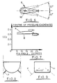
- Figure 6 illustrates the adjustment of the operating angle of the fin about the axis 32 with a 20° angle of adjustment both above and below a position of zero deflection shown in full lines.
- the centre of pressure for the fin section is located approximately at the zone of maximum thickness t (see Figure 10).
- Figure 7 shows the movement of the position of the centre of pressure for a range of angular deflections for the prior art fin shown in Figures 1 and 3 (curve A) and for the fin of Figure 5 (curve B).
- the upper curve A shows the amount of movement of the chordwise centre of pressure (CCp) over the range 5° - 20°
- the lower curve (B) illustrates that the centre of pressure of the fin according to the present invention shows virtually no change in the same range.
- the optimum shaft position (on axis 32) occurs at a zone where the largest diameter shaft can be accommodated. Because three is so little movement of the centre of pressure along the fore-and-aft chord line 30, with increasing fin angle, it will be appreciated that a relatively small torque is required to operate the fin over the preferred operating range.
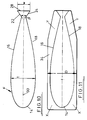
- Figures 10 and 11 illustrate more clearly a preferred profile or outline for the cross-section of a fin F according to the invention, Figure 11 shown also the provision of a plate 34.
- the value of t as 0.26 c has the advantage that a suitably large structure is available in which to mount a shaft 36 along the axis 32 to sustain the various levels of imposed loads.
- the value of w which is selected to be 50% of that of t gives a compromise between adequate lift and an acceptable level of drag.
- the value for ⁇ is selected bearing in mind that the more shallow the angle the less drag and lift.
- a value of 70° is given by way of the present example, a value as low as 20° may be used.
- the value of w is suitably increased by way of compensation.
- Figure 11 shows the preferred profile of the tip fence plate 34. Since the maximum areas of effective operation of the plate 34 are at the positions X and Y, the outline of the plate 34 has been chosen to reduce its height, dimension D, to a minimum. This facility has the practical advantage that the mouth opening of the hull recess can be reduced accordingly.
Landscapes
- Chemical & Material Sciences (AREA)
- Engineering & Computer Science (AREA)
- Combustion & Propulsion (AREA)
- Mechanical Engineering (AREA)
- Ocean & Marine Engineering (AREA)
- Bridges Or Land Bridges (AREA)
- Toys (AREA)
- Hydraulic Turbines (AREA)
- Soil Working Implements (AREA)
- Structures Of Non-Positive Displacement Pumps (AREA)
Abstract
Claims (6)
- Aileron stabilisateur hydrodynamique destiné à l'utilisation à l'état immergé sur des embarcations aquatiques, cet aileron comprenant un élément unique monobloc avec une portion de corps allongé (F) ayant une section transversale de façon générale aérodynamique comprenant une portion allant en s'amenuisant à partir de sa zone d'attaque (14) jusqu'à sa zone de fuite (20), une portion en forme de crête (26) ayant une section transversale au moins sensiblement en forme de coin et étant disposée en un emplacement à l'arrière de cette portion allant en s'amenuisant, la section transversale divergente en forme de coin (22,24) selon la direction et aboutissant dans une paroi d'extrémité (28), des moyens de montage (32,36) étant prévus pour monter l'élément de façon à faire saillie dans l'utilisation à partir d'une coque (8) de l'embarcation.
- Aileron selon la revendication 1, dans lequel la paroi d'extrémité (28) se situe au moins sensiblement dans un plan transversal à ladite direction.
- Aileron selon l'une ou l'autre des revendications 1 et 2, dans lequel le profil de la paroi d'extrémité (28) est de géométrie plane concave ou comprend un angle obtus ou aigu.
- Aileron selon l'une quelconque des revendications précédentes, dans lequel l'élément monobloc est monté sur un axe (36) par rapport à la coque (8) pour la rotation autour d'un axe (32) sensiblement transversal à une ligne s'étendant de l'avant à l'arrière de la coque, cette rotation donnant un angle de fonctionnement variable en continu dans une plage prédéterminée.
- Aileron selon la revendication 1, dans lequel les surfaces divergentes (22,24) de l'élément en forme de crête (26) sont disposées de façon à inclure un angle entre 20° et 90°.
- Aileron selon l'une quelconque des revendications précédentes, muni d'une plaque pour protection d'extrémité (34) sur son extrémité hors bord.
Applications Claiming Priority (3)
| Application Number | Priority Date | Filing Date | Title |
|---|---|---|---|
| GB919100116A GB9100116D0 (en) | 1991-01-04 | 1991-01-04 | Hydrodynamic fin for water-borne craft |
| GB9100116 | 1991-01-28 | ||
| PCT/GB1991/002310 WO1992012046A1 (fr) | 1991-01-04 | 1991-12-23 | Aileron hydrodynamique pour navire |
Publications (2)
| Publication Number | Publication Date |
|---|---|
| EP0571401A1 EP0571401A1 (fr) | 1993-12-01 |
| EP0571401B1 true EP0571401B1 (fr) | 1997-06-25 |
Family
ID=10687942
Family Applications (1)
| Application Number | Title | Priority Date | Filing Date |
|---|---|---|---|
| EP92902381A Expired - Lifetime EP0571401B1 (fr) | 1991-01-04 | 1991-12-23 | Aileron hydrodynamique pour navire |
Country Status (5)
| Country | Link |
|---|---|
| EP (1) | EP0571401B1 (fr) |
| JP (1) | JPH06506888A (fr) |
| DE (2) | DE571401T1 (fr) |
| GB (2) | GB9100116D0 (fr) |
| WO (1) | WO1992012046A1 (fr) |
Families Citing this family (5)
| Publication number | Priority date | Publication date | Assignee | Title |
|---|---|---|---|---|
| FR2728864B1 (fr) * | 1994-12-29 | 1997-03-14 | Havre Chantiers | Dispositif de stabilisation a volets au bord de fuite pour stabilisateurs anti-roulis de navire |
| FR2736888B1 (fr) * | 1995-07-21 | 1997-09-26 | Havre Chantiers | Dispositif de stabilisation anti-tangage pour navire |
| FR2766004B1 (fr) * | 1997-07-11 | 1999-12-03 | Framatome Sa | Plaquettes de grille pour assemblage combustible nucleaire et grille comportant de telles plaquettes |
| IT1311861B1 (it) | 1999-09-22 | 2002-03-19 | Fincantieri Cantieri Navali It | Struttura di pinna stabilizzatrice |
| CN102602510B (zh) * | 2011-12-15 | 2015-07-22 | 深圳市海斯比船艇科技股份有限公司 | 抗撞减摇型单体船 |
Family Cites Families (4)
| Publication number | Priority date | Publication date | Assignee | Title |
|---|---|---|---|---|
| NO134459C (fr) * | 1971-12-17 | 1976-10-13 | Nicolaus Kaufer | |
| NL174127C (nl) * | 1973-01-24 | Werftunion Gmbh & Co | Eendelig, in zijaanzicht rechthoekig, roer met verticale zijwanden en een symmetrisch profiel. | |
| DE3303424A1 (de) * | 1983-02-02 | 1984-08-09 | Werftunion Gmbh & Co, 4600 Dortmund | Symmetrische ruderprofile fuer maximale querkraefte bei gleichzeitig maximaler kursstabilitaet |
| US5046444A (en) * | 1990-04-10 | 1991-09-10 | Michigan Wheel Corp. | Base vented subcavitating hydrofoil section |
-
1991
- 1991-01-04 GB GB919100116A patent/GB9100116D0/en active Pending
- 1991-12-23 JP JP4502542A patent/JPH06506888A/ja active Pending
- 1991-12-23 DE DE0571401T patent/DE571401T1/de active Pending
- 1991-12-23 DE DE69126669T patent/DE69126669T2/de not_active Expired - Fee Related
- 1991-12-23 WO PCT/GB1991/002310 patent/WO1992012046A1/fr not_active Ceased
- 1991-12-23 EP EP92902381A patent/EP0571401B1/fr not_active Expired - Lifetime
-
1993
- 1993-06-15 GB GB9312342A patent/GB2266073B/en not_active Expired - Fee Related
Also Published As
| Publication number | Publication date |
|---|---|
| JPH06506888A (ja) | 1994-08-04 |
| DE571401T1 (de) | 1994-10-06 |
| EP0571401A1 (fr) | 1993-12-01 |
| GB9100116D0 (en) | 1991-02-20 |
| GB9312342D0 (en) | 1993-08-18 |
| DE69126669T2 (de) | 1998-01-08 |
| DE69126669D1 (de) | 1997-07-31 |
| WO1992012046A1 (fr) | 1992-07-23 |
| GB2266073B (en) | 1994-06-22 |
| GB2266073A (en) | 1993-10-20 |
Similar Documents
| Publication | Publication Date | Title |
|---|---|---|
| EP2160319B1 (fr) | Bateau dont la poupe est équipée d un dispositif pour défléchir un flux d eau | |
| US5448963A (en) | Hydrofoil supported planing watercraft | |
| US8881664B2 (en) | Method for maintaining the heading of a ship | |
| US11738827B2 (en) | Hydrofoil system and marine vessel | |
| US4280433A (en) | Underwater appendages for vessels | |
| US6805068B1 (en) | Hydrofoil system for lifting a boat partially out of water an amount sufficient to reduce drag | |
| KR101644506B1 (ko) | 흘수선 아래로 포일이 장착된 선박 | |
| US4615291A (en) | Hydrofoil boat | |
| CA2472250C (fr) | Voilier mu par le vent | |
| EP0571401B1 (fr) | Aileron hydrodynamique pour navire | |
| US3424120A (en) | Hydrotunnel boat | |
| US4959032A (en) | Water craft with guide fins | |
| AU2003207004A1 (en) | Watercraft | |
| US5141456A (en) | Water craft with guide fins | |
| US7617793B2 (en) | Vessel provided with a foil situated below the waterline | |
| US6964240B1 (en) | Hull for high speed water craft | |
| EP1477402B1 (fr) | Dispositif de regulation des mouvements de une coque de bateau | |
| US3804047A (en) | Retraction arrangement for the bow foil of hydrofoil craft | |
| US5263433A (en) | Hybrid hydrofoil strut leading edge extension | |
| JPH06510498A (ja) | 風力を動力もしくは補助動力とする水中翼船 | |
| GB2279620A (en) | Sailing vessel | |
| WO1987002641A1 (fr) | Systeme de manoeuvre pour bateau semi-submerge rapide | |
| JP2002539018A (ja) | 滑走および半滑走船用の船殻 |
Legal Events
| Date | Code | Title | Description |
|---|---|---|---|
| PUAI | Public reference made under article 153(3) epc to a published international application that has entered the european phase |
Free format text: ORIGINAL CODE: 0009012 |
|
| 17P | Request for examination filed |
Effective date: 19931007 |
|
| AK | Designated contracting states |
Kind code of ref document: A1 Designated state(s): DE FR IT |
|
| ITCL | It: translation for ep claims filed |
Representative=s name: STUDIO TORTA SOCIETA' SEMPLICE |
|
| EL | Fr: translation of claims filed | ||
| 17Q | First examination report despatched |
Effective date: 19940610 |
|
| DET | De: translation of patent claims | ||
| GRAG | Despatch of communication of intention to grant |
Free format text: ORIGINAL CODE: EPIDOS AGRA |
|
| GRAH | Despatch of communication of intention to grant a patent |
Free format text: ORIGINAL CODE: EPIDOS IGRA |
|
| GRAH | Despatch of communication of intention to grant a patent |
Free format text: ORIGINAL CODE: EPIDOS IGRA |
|
| GRAA | (expected) grant |
Free format text: ORIGINAL CODE: 0009210 |
|
| AK | Designated contracting states |
Kind code of ref document: B1 Designated state(s): DE FR IT |
|
| REF | Corresponds to: |
Ref document number: 69126669 Country of ref document: DE Date of ref document: 19970731 |
|
| ITF | It: translation for a ep patent filed | ||
| ET | Fr: translation filed | ||
| PLBE | No opposition filed within time limit |
Free format text: ORIGINAL CODE: 0009261 |
|
| STAA | Information on the status of an ep patent application or granted ep patent |
Free format text: STATUS: NO OPPOSITION FILED WITHIN TIME LIMIT |
|
| 26N | No opposition filed | ||
| PGFP | Annual fee paid to national office [announced via postgrant information from national office to epo] |
Ref country code: FR Payment date: 19991208 Year of fee payment: 9 |
|
| PGFP | Annual fee paid to national office [announced via postgrant information from national office to epo] |
Ref country code: DE Payment date: 19991230 Year of fee payment: 9 |
|
| PG25 | Lapsed in a contracting state [announced via postgrant information from national office to epo] |
Ref country code: FR Free format text: LAPSE BECAUSE OF NON-PAYMENT OF DUE FEES Effective date: 20010831 |
|
| REG | Reference to a national code |
Ref country code: FR Ref legal event code: ST |
|
| PG25 | Lapsed in a contracting state [announced via postgrant information from national office to epo] |
Ref country code: DE Free format text: LAPSE BECAUSE OF NON-PAYMENT OF DUE FEES Effective date: 20011002 |
|
| PG25 | Lapsed in a contracting state [announced via postgrant information from national office to epo] |
Ref country code: IT Free format text: LAPSE BECAUSE OF NON-PAYMENT OF DUE FEES;WARNING: LAPSES OF ITALIAN PATENTS WITH EFFECTIVE DATE BEFORE 2007 MAY HAVE OCCURRED AT ANY TIME BEFORE 2007. THE CORRECT EFFECTIVE DATE MAY BE DIFFERENT FROM THE ONE RECORDED. Effective date: 20051223 |