EP0571658B1 - Système de stockage avec emplacements de stockage tournants - Google Patents
Système de stockage avec emplacements de stockage tournants Download PDFInfo
- Publication number
- EP0571658B1 EP0571658B1 EP92117297A EP92117297A EP0571658B1 EP 0571658 B1 EP0571658 B1 EP 0571658B1 EP 92117297 A EP92117297 A EP 92117297A EP 92117297 A EP92117297 A EP 92117297A EP 0571658 B1 EP0571658 B1 EP 0571658B1
- Authority
- EP
- European Patent Office
- Prior art keywords
- storage
- access
- storage unit
- access region
- units
- Prior art date
- Legal status (The legal status is an assumption and is not a legal conclusion. Google has not performed a legal analysis and makes no representation as to the accuracy of the status listed.)
- Expired - Lifetime
Links
Images



Classifications
-
- B—PERFORMING OPERATIONS; TRANSPORTING
- B65—CONVEYING; PACKING; STORING; HANDLING THIN OR FILAMENTARY MATERIAL
- B65G—TRANSPORT OR STORAGE DEVICES, e.g. CONVEYORS FOR LOADING OR TIPPING, SHOP CONVEYOR SYSTEMS OR PNEUMATIC TUBE CONVEYORS
- B65G1/00—Storing articles, individually or in orderly arrangement, in warehouses or magazines
- B65G1/02—Storage devices
- B65G1/04—Storage devices mechanical
- B65G1/12—Storage devices mechanical with separate article supports or holders movable in a closed circuit to facilitate insertion or removal of articles the articles being books, documents, forms or the like
- B65G1/133—Storage devices mechanical with separate article supports or holders movable in a closed circuit to facilitate insertion or removal of articles the articles being books, documents, forms or the like the circuit being confined in a horizontal plane
Definitions
- the invention relates generally to storage and feed systems, and in particular to a new and improved storage system that allows access to both sides of a storage unit that is in an access position.
- Such storage and feed conveyor systems are already known.
- a plurality of storage units such as racks or containers, are provided which are attached to an oval, driven conveyor.
- Such conveyors are generally provided with an oval rail which has straight sides and semicircular ends.
- access to the storage units is provided at one of the circular ends.
- each storage unit or rack provides first and second opposing access fronts. A first storage area is accessible from an access front, while a second storage area is accessible from the opposite access front.
- two separate storage areas are accessible in each switching position of the conveyor, one of the storage areas is located within one storage unit, while the other of the storage areas is arranged in the adjacent storage unit. In such a system, the conveyor must be switched to two different separate positions to allow access to either side of a single storage unit.
- a generic storage system in which a plurality of storage units are combined in several transport units.
- the transport units can be moved from a storage zone to an access area via a rail guide.
- each transport unit can be rotated in an unspecified manner in order to gain access to the individual storage units from two opposite sides.
- the invention offers a variety of important aspects and advantages.
- the invention provides a storage and delivery system on which a plurality of storage units are attached to a bracket to move between a storage zone and an access zone. Each of the storage units is attached such that it can be rotated in the manner of a rotating tray while remaining in the access position.
- a predetermined storage unit is brought into the access position. While this storage unit remains in the access position, it can be rotated to make at least two different sides accessible.
- each bearing unit is provided with two opposite sides.
- a first storage area is accessible from a first side, while another separate storage area is accessible from the other side.
- the storage units are arranged such that these two sides correspond to the same, corresponding access sides of the next adjacent storage unit when the units are in the storage zone.
- the storage unit When the access position is reached, the storage unit can be rotated 90 ° in opposite directions into so-called operating positions in order to present one or the other access side in the direction of the operator in the access position.
- full access to each access front of a storage unit can be made while the conveyor remains in its set position.
- the system is completely driven both with regard to the individual switching positions of the conveyor and with respect to the rotation of the bearing unit in the access position.
- Feedback and feedback sensors are also provided so that the system can be fully automated.
- the conveyor system according to the present invention can be loaded with such articles, a predetermined style, color and size being arranged in a predetermined frame or within a predetermined container.
- this order is entered into a computer control which controls the supply conveyor.
- the conveyor then works under the computer control, which switches the conveyor to move the storage units containing the desired articles into the access position.
- the storage unit is then automatically rotated to position the desired side of the storage unit for access towards the person who is to perform the job.
- a light post or similar display device is provided, which shows the person who is compiling the order the number of articles in a given container that are required to execute the respective order.
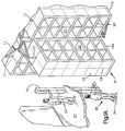
- Fig. 1 shows schematically the overall structure of a carousel-type storage and feeding system according to the present invention.
- the machine has a stationary frame, each with upper and lower oval raceways or rails 11, 12. On these rails for movement along the oval, a transporter 13 or a carrying device which travels in the closed loop is arranged.
- a motorized drive 14 attached to the frame causes the support 13 to move along the rails to any one of a variety of switch positions.
- a plurality of container-like storage units 16 are fastened to the carrying device 13. Each of these bearing units 16 is articulated or rotatably held on an adjacent region of the support device 13 on a vertical rotary shaft 17. This rotary shaft 17 extends vertically and centrally or centrally through the various containers 18 of the associated bearing unit 16.
- each of the containers 18 has a central wall 19 which divides the storage container into a first storage zone 21 on one side of the central wall 19 and a second storage zone 22 on the opposite side of the central wall 19 occurs.
- the storage zone 21 is accessible via a first side 23 of the container that belongs together and the second storage zone 22 is accessible through a second or opposite side of the container belonging together.
- the bearing units 16 are attached such that when the bearing units extend along the straight sides of the oval, the first side 23 of each bearing unit is substantially adjacent to the second side 24 of the adjacent bearing unit. Furthermore, it is advisable to dimension the bearing units so that they have a radial length A which is greater than their depth B. If such dimensions are used, the storage volume of the entire system is larger than it is for a predetermined amount of floor space would if the length were decreased.
- the carousel rail has two straight sides 26 and 27, which are connected at their ends via semicircular end regions 28 and 29.
- An access area 31 is in alignment with the semicircular end area 28. In this access position, the storage unit 16 can be loaded or stored articles can be removed from it.
- a relatively large carousel is shown with storage containers which are arranged in upper and lower sectors 32 and 33.
- a first operator 36 standing on a platform 37 can comfortably reach the containers in the upper sector 32, while a second operator 38 on a lower platform or floor 39 has easy access to the containers in the lower area 33.
- carousels can be built with a substantial or large height in order to use the fully available height of a building in which the carousel unit is located.
- Fig. 1 the straight sides 26 and 27 are relatively short, so that the entire unit can be shown on a single side of the drawing. In practice, however, the carousel is usually much longer, so that a variety of storage units 16 can be used.
- a storage unit rotating device 41 which is operated to couple a storage unit 16a, which has been fed to the access area 31, by the operation of the motor drive 14.
- a storage unit 16a When each of the storage units 16a first reaches the access position, that storage unit is in a normal orientation, shown in Fig. 1A, in which its length extends radially from the rails and the ends 42 of the containers 18 are adjacent to the two operators 36 and 38.
- the bearing unit 16a is rotated 90 ° in one or the other direction in order to position either side 23 or 24 within a short distance from the operators 36 and 38, as shown in FIG 1 is shown.
- FIGS. 2 to 4 show the structure of the rotating device 41.
- the rotating unit 41 is provided with a base plate 46 which carries an electric motor 47 within the adjacent area of the lower rail 12.
- a turntable 48 which is rotatably mounted on the base plate for rotation about a vertical axis on a pivot pin 49.
- a drive belt 21 connects the motor 47 to the turntable 48 so that the motor can be operated to move the turntable 90 ° from the normal position of the turntable as shown in Figs. 2, 3 and 3A, to turn.
- rollers 52, 53, 54 and 55 are fastened to the rotary table.
- the rollers 52 and 55 are spaced apart from one another and an equal distance is provided between the rollers 53 and 54. This distance is sized to allow a blade or blade 56 mounted on the lower end of the connecting rotary shaft 17 to be brought into position between the rollers.
- the rollers 52 and 53 are arranged on the outer side of the sheet 56, while the rollers 54 and 55 are arranged on the opposite or inner side of the sheet 56.
- the rollers act as opposing stops or abutments that form a coupling or connection with the blade 56.
- the various proportions are chosen such that when a particular storage unit is moved to the access area 31 by operation of the motor drive 14, the blade 56 attached to the lower end of the associated rotary shaft 17 will move to a position between the above Rolling moves.
- the blade and rollers therefore provide a coupling so that rotation of the turntable 48 by the motor 47 results in rotation of the entire bearing unit 16A in a direction determined by the direction of rotation of the motor 47.
- the rotary movement extends of the bearing units over an angle of 90 ° in each direction from the normal orientation of the bearing units shown in Figures 1A, 2, 3 and 3A.
- a measuring device 57 is arranged adjacent to the belt 51 and has three sensors 57a, 57b and 57c. These sensors generate a signal when a sensor plate 58 attached to the belt moves along the sensors. When the plate 58 is placed on the sensor 57b, a signal is generated to indicate that the turntable and the associated bearing unit are in their normal orientation for the operation of the support device 13. When the plate is placed on sensor 57c, a signal is generated to indicate that the turntable and associated bearing unit 16 have rotated clockwise or clockwise through 90 ° to position the second side 24 of bearing unit 16a , where page 24 is easily accessible for both operators 36 and 38.
- a locking system is provided to lock each of the bearing units 16 in their normal orientation for storage and switching operations.
- This locking system which normally prevents the various bearing units 16 from rotating, is released (deactivated) when the corresponding bearing unit is in the access position and must be rotated by the rotating unit as described above.
- a locking plate 46 is located on the lower end of the rotary shaft 17.
- the rotary shaft is mounted on an adjacent area of the carrying device 13.
- the locking plate is provided with a radially extending slot 67.
- a locking lever 69 is pivoted at 69a on a support bracket 13a. Outer end 69b normally sits in slot 67 and prevents plate 66 from moving out of its normal orientation. On the other hand, this ensures that the rotary shaft 17 and the associated bearing unit are in a neat position for shifting and storing.
- a linear actuating device 71 is attached to the rotating device 41 and is arranged below the inner end of the locking lever 69 when the corresponding bearing unit is moved into the access position 31.
- the inner end 69c of the locking lever 69 is larger and heavier than the outer end 69b. Therefore, gravity normally maintains the outer end 69b in the locked position within the slot 67.
- the actuator 71 is operated to raise the inner end 69c that the outer end 69b is rotated downward out of the slot 67.
- the outer end slides along the lower side of the plate even if the actuator is deactivated.
- the actuating device 71 When the rotating device returns the storage unit from the access position to its normal orientation, the actuating device 71 is deactivated and gravity causes the outer end to move up to the locking position.
- the outer end 69b is provided with bevels 69d to facilitate such movement.
- the storage unit is then locked in its normal orientation. At this moment, the blade position is aligned so that the main drive 14 can continue to rotate the carousel to guide another storage unit to the access position.
- a second measuring system is also provided when a specific, special storage unit is in the access position.
- This measuring system 70 has sensor cells 70a, which read imprints which are printed on a plate 13a, which in turn is mounted on the support device 13 below each of the corresponding bearing units 16.
- the signals generated by this measuring system are normally fed to a control device 75 which automates the operation of the system.
- a light pole or pole or the like display device 73 is preferably provided if the carousel operation is fully automated. Such a light pole is connected to a control computer 75 and shows the respective operators 36 and 38 the containers from which articles are to be removed and the numbers of these articles which are to be removed. This greatly facilitates the execution of the orders and avoids the need for operators to use order slips.
- the rotary system shown is arranged on the lower level or on the floor, it can also be arranged at the upper end of the bearing units.
- FIGS. 5 and 6 show another form of the storage units, which are used for storage and for making them accessible of small items of clothing can be used.
- open frames 81 which are vertically spaced from one another, are arranged on a rotary shaft 17 and can be rotated back into the access position by 90 ° in any direction from their normal bearing direction.
- the individual individual parts are preferably held on hanging devices 82, which in turn are arranged on the open frame 81 and can be removed therefrom.
- Each hanging unit 82 is provided with a handle so that operators can remove or replace the hanging unit from the open frame.
- each suspension device provides a U-shaped rod holder on which individual brackets can be hung.
- the rod holder 83 has a hook-shaped end 86 that is configured to receive the opposite end 87 of the rod holder to form a closed retention system and to prevent the hangers from accidentally sliding off the rod holder.
- the end 87 is removed from the hook-shaped end 86 so that it is possible to move it down to the dashed position so that the desired number of brackets 84 can be removed.
- the bearing units are arranged with the open frame for rotational movement to allow access to opposite sides of the bearing unit in exactly the same way as in the first embodiment.
- the rotating unit 41 rotates this storage unit through an angle of 90 ° either clockwise or counterclockwise, so that one or to arrange the other side 23 or 24 to the front so that the operator has easy access to the respective side.
- the rotating device 41 and the motor drive 14 are preferably computer-controlled for essentially fully automatic operation by a computer, which is indicated schematically at 75 and which is connected to the various sensors and drive units described above.
- each storage zone 21 or 22 of each container 18 is filled with a number of a certain category of articles; e.g. when the carousel is used to store and access small items of clothing, each container loaded with a number of such parts of one color, style or size, and other containers filled with articles of a different style, size and color . Furthermore, more than one type of an article can be stored in the overall carousel system.
- this request is preferably fed to the control computer 75, which also contains information about which special containers have the respective styles, colors and sizes of articles.
- the computer then gives a command to the motor drive to move a particular container-like storage unit 16 into the access position 31.
- the same computer then controls the rotating device which brings the desired side of the containers of the storage unit 16 into the access position opposite the operators 36 and 39.
- the light pillar 73 which is arranged adjacent to the two operators 36 and 38, preferably shows and is also controlled by the computer, the number of parts or articles to be removed from the particular containers, which are then adjacent to the operators, so as to execute the respective request or command.
- the machine After the required number and types of articles have been removed from the now accessible containers by the two operators, the machine either rotates the storage unit into the access position 31 to present the opposite side for further order fulfillment or rotates the container back in the storage direction, so that the carrying device can be rotated further to bring the next desired storage unit into the access position.
- the locking system holds the storage units in the corresponding storage direction, except when they are turned to the access position.
Landscapes
- Engineering & Computer Science (AREA)
- Mechanical Engineering (AREA)
- Warehouses Or Storage Devices (AREA)
- Automatic Disk Changers (AREA)
- Refuse Collection And Transfer (AREA)
- Memory System Of A Hierarchy Structure (AREA)
- Apparatus For Radiation Diagnosis (AREA)
Claims (7)
- Système de stockage comprenant un grand nombre d'unités de stockage (16), chaque unité de stockage (16) étant accessible à partir de deux côtés mutuellement opposés, avec un transporteur (13) qui déplace les unités de stockage (16), au moyen d'un guidage par glissières, d'une zone de stockage à une zone d'accès (31), le transporteur (13) maintenant une unité de stockage (16) considérée, dans la zone d'accès, de manière qu'un mouvement de rotation soit possible dans cette zone d'accès (31), caractérisé en ce qu'un dispositif de rotation (41), pourvu de galets (52-55), est prévu dans la zone d'accès (31) ; en ce qu'un arbre tournant (17), implanté sur chaque unité de stockage (16), présente une pale (56) pouvant être mise en prise avec les galets (52-55), et il est prévu un dispositif de commande par l'intermédiaire duquel les galets (52-55) du dispositif de rotation (41) peuvent tourner avec la pale (56) de l'arbre tournant (17) et avec l'unité de stockage (16) respectivement associée, et un dispositif de verrouillage verrouille les unités de stockage par l'intermédiaire du transporteur (13), d'une manière interdisant une rotation ; et en ce qu'une unité de stockage (16) située dans la zone d'accès (31) peut être déverrouillée, par l'intermédiaire du dispositif de verrouillage, pour permettre une rotation de cette unité de stockage (16) jusqu'à une position d'accès.
- Système de stockage selon la revendication 1, caractérisé en ce que les unités de stockage (16) sont retenues, par l'intermédiaire du transporteur (13), dans une position fixe par rapport au guidage par glissières, une rotation de 90° des unités de stockage (16) étant prévue dans la zone d'accès (31).
- Système de stockage selon la revendication 1 ou 2, caractérisé par la présence de capteurs qui engendrent un premier signal lorsqu'une unité de stockage déterminée se trouve dans la zone d'accès, et engendrent un second signal indiquant la position que l'unité de stockage (16) a prise, par rotation, dans la zone d'accès ; et en ce qu'une unité de stockage déterminée peut être amenée automatiquement, par l'intermédiaire du dispositif de commande, à la zone d'accès (31) et à la position d'accès.
- Système de stockage selon l'une quelconque des revendications précédentes, caractérisé en ce qu'un dispositif d'affichage, prévu au voisinage de la zone d'accès (31), est commandé par le dispositif de commande et affiche l'emplacement considéré des articles devant être prélevés de l'unité de stockage.
- Système de stockage selon l'une quelconque des revendications précédentes, caractérisé en ce que les unités de stockage (16) sont réalisées sous la forme de châssis ou de cadres ouverts, auxquels des articles peuvent être suspendus.
- Système de stockage selon l'une quelconque des revendications précédentes, caractérisé en ce qu'une unité de stockage présente des réceptacles pour le stockage d'articles.
- Système de stockage selon l'une quelconque des revendications précédentes, caractérisé en ce que les unités de stockage (16) sont d'une hauteur telle qu'un opérateur nécessite des moyens auxiliaires pour pouvoir manier l'ensemble des unités de stockage (16).
Applications Claiming Priority (2)
| Application Number | Priority Date | Filing Date | Title |
|---|---|---|---|
| US07/889,811 US5207335A (en) | 1992-05-29 | 1992-05-29 | Carousel conveyor with rotatable storage racks |
| US889811 | 1992-05-29 |
Publications (2)
| Publication Number | Publication Date |
|---|---|
| EP0571658A1 EP0571658A1 (fr) | 1993-12-01 |
| EP0571658B1 true EP0571658B1 (fr) | 1997-06-04 |
Family
ID=25395840
Family Applications (1)
| Application Number | Title | Priority Date | Filing Date |
|---|---|---|---|
| EP92117297A Expired - Lifetime EP0571658B1 (fr) | 1992-05-29 | 1992-10-09 | Système de stockage avec emplacements de stockage tournants |
Country Status (8)
| Country | Link |
|---|---|
| US (1) | US5207335A (fr) |
| EP (1) | EP0571658B1 (fr) |
| JP (1) | JPH05338733A (fr) |
| AT (1) | ATE153969T1 (fr) |
| DE (1) | DE59208584D1 (fr) |
| DK (1) | DK0571658T3 (fr) |
| ES (1) | ES2102436T3 (fr) |
| GR (1) | GR3023918T3 (fr) |
Families Citing this family (24)
| Publication number | Priority date | Publication date | Assignee | Title |
|---|---|---|---|---|
| US5330062A (en) * | 1992-11-10 | 1994-07-19 | White Consolidated Industries, Inc. | Light tree display for a horizontal carousel |
| US5636750A (en) * | 1993-05-10 | 1997-06-10 | Richards-Wilcox, Inc. | Method and apparatus for automatically locating an item in a movable storage system |
| US5651469A (en) * | 1995-03-13 | 1997-07-29 | Richards-Wilcox, Inc. | Garment rack assembly |
| US5735414A (en) * | 1996-07-29 | 1998-04-07 | Lo; Chiu-Hsiang | Swivel-type coat hanger assembly |
| US5813547A (en) * | 1997-01-28 | 1998-09-29 | Rice; Sherrie D. | Clothing accessories storage rack |
| DE10015329A1 (de) * | 2000-03-28 | 2001-10-04 | Volkswagen Ag | Vorrichtung zum Lagern von Montagebauteilen, insbesondere für die Motor- und Fahrzeugmontage |
| US6431376B1 (en) | 2000-06-08 | 2002-08-13 | White Systems, Inc. | Storage bin assembly having unitary side and backwall supports |
| EP1273531A1 (fr) * | 2001-07-02 | 2003-01-08 | Crisplant A/S | Un systême de stockage pour stocker des articles à distribuer |
| US6585119B2 (en) | 2001-08-24 | 2003-07-01 | Saul Palder | Modular storage system for multiple stacks |
| US6698854B1 (en) * | 2002-01-07 | 2004-03-02 | Mag-Nif Incorporated | Key organizer |
| ES2253509T3 (es) * | 2002-03-19 | 2006-06-01 | Swisslog Italia S.P.A. | Almacen modular automatico. |
| US7769486B2 (en) * | 2002-06-14 | 2010-08-03 | Spacesaver Corporation | Remote interface for a mobile storage system or other equipment |
| DE10331741A1 (de) * | 2003-07-11 | 2005-01-27 | Jens Emmerling | Lagersystem |
| US7363104B2 (en) * | 2003-08-15 | 2008-04-22 | Sk Daifuku Corporation | Product storage and picking system and method of storing and picking products |
| US20060169653A1 (en) * | 2005-02-01 | 2006-08-03 | Saul Palder | Storage system with turntable swingable about multiple axes |
| US8439211B2 (en) * | 2005-09-16 | 2013-05-14 | Ray R. Emrani | Visual organization and display apparatus and system |
| US7997371B2 (en) * | 2009-03-17 | 2011-08-16 | Vasyl Khymych | Airflow power installations |
| US9435975B2 (en) * | 2013-03-15 | 2016-09-06 | Commscope Technologies Llc | Modular high density telecommunications frame and chassis system |
| US20150122757A1 (en) * | 2013-11-05 | 2015-05-07 | Three Paths, LLC | Moveable organizer |
| SG11201703434TA (en) | 2014-10-27 | 2017-06-29 | Shenzhen Whalehouse Tech Company Ltd | Automatic warehouse control system and method |
| EP3214022A4 (fr) * | 2014-10-27 | 2018-11-14 | Shenzhen Whalehouse Technology Company Limited | Appareil d'entrepôt dense automatique |
| US10330256B2 (en) | 2016-12-08 | 2019-06-25 | Douglas Michael Eckhart | Column grip |
| CN110937295B (zh) * | 2018-09-21 | 2025-10-21 | 北京京东乾石科技有限公司 | 配送站 |
| CN109230195B (zh) * | 2018-10-29 | 2020-07-28 | 烟台五神生物科技有限公司 | 一种医用传送装置 |
Family Cites Families (7)
| Publication number | Priority date | Publication date | Assignee | Title |
|---|---|---|---|---|
| FR1198598A (fr) * | 1958-01-28 | 1959-12-08 | Dispositif à casier pour le stockage d'objets divers | |
| US3780852A (en) * | 1972-02-02 | 1973-12-25 | White Machine Co | Article storage and retrieval apparatus |
| JPS6127808A (ja) * | 1984-07-16 | 1986-02-07 | Okamura Seisakusho:Kk | 回転式収納棚 |
| US4723819A (en) * | 1986-06-12 | 1988-02-09 | Shoe Spa Inc. | Merchandizing device |
| US4821888A (en) * | 1987-10-29 | 1989-04-18 | Hankes William P | Carousel material handling apparatus |
| US5065872A (en) * | 1990-10-05 | 1991-11-19 | White Storage & Retrieval Systems, Inc. | Dual access storage and retrieval system |
| US5062536A (en) * | 1990-11-15 | 1991-11-05 | Tung Keng Col, Ltd. | Rotatable hanger assembly |
-
1992
- 1992-05-29 US US07/889,811 patent/US5207335A/en not_active Expired - Fee Related
- 1992-10-07 JP JP4268560A patent/JPH05338733A/ja active Pending
- 1992-10-09 EP EP92117297A patent/EP0571658B1/fr not_active Expired - Lifetime
- 1992-10-09 DK DK92117297.9T patent/DK0571658T3/da active
- 1992-10-09 AT AT92117297T patent/ATE153969T1/de not_active IP Right Cessation
- 1992-10-09 ES ES92117297T patent/ES2102436T3/es not_active Expired - Lifetime
- 1992-10-09 DE DE59208584T patent/DE59208584D1/de not_active Expired - Fee Related
-
1997
- 1997-06-26 GR GR970401566T patent/GR3023918T3/el unknown
Also Published As
| Publication number | Publication date |
|---|---|
| DK0571658T3 (da) | 1997-09-01 |
| ES2102436T3 (es) | 1997-08-01 |
| GR3023918T3 (en) | 1997-09-30 |
| EP0571658A1 (fr) | 1993-12-01 |
| DE59208584D1 (de) | 1997-07-10 |
| JPH05338733A (ja) | 1993-12-21 |
| ATE153969T1 (de) | 1997-06-15 |
| US5207335A (en) | 1993-05-04 |
Similar Documents
| Publication | Publication Date | Title |
|---|---|---|
| EP0571658B1 (fr) | Système de stockage avec emplacements de stockage tournants | |
| DE4118074C2 (fr) | ||
| DE69924537T2 (de) | Anpassbare automatische maschine für die orientierung und ausgerichtete zuführung von leichten hohlartikeln | |
| EP0236812B1 (fr) | Chariot porte-outils pour le chargement des machines-outils | |
| DE3742096A1 (de) | Werkzeugmagazin | |
| EP1441026A1 (fr) | Système de stockage automatique et armoire de climatisation avec un tel système de stockage automatique | |
| EP0376035B1 (fr) | Fichier à manèges multiples | |
| DE4118108C2 (fr) | ||
| DE102015201565A1 (de) | Kommissioniervorrichtung in Form eines Drehtisches | |
| DE3517634A1 (de) | Vorrichtung zum auswechseln von plattenzylindern | |
| DE69405307T2 (de) | Maschine zum Einwickeln von Schalen in streckbarer Folie | |
| EP0044947B1 (fr) | Dispositif pour le refroidissement ou le séchage de matière à gros grain en vrac | |
| DE4317144C2 (de) | Regallager | |
| DE3517061C1 (de) | Regalfoerderzeug in Form eines Kranes | |
| DE69005400T2 (de) | Aufbewahrungsschrank für zahlreiche kleine Gegenstände. | |
| DE3736122C1 (de) | Hubvorrichtung fuer Langgut | |
| DE3133108C1 (de) | Einrichtung zur Lagerung von stangenfoermigem Material und zur Versorgung einer Trennmaschine mit diesen Material | |
| EP0308363B1 (fr) | Rayonnage circulant | |
| EP1502696A1 (fr) | Magasin à outils avec dispositif de manutention et accesible depuis l'extérieur. | |
| EP0261410A1 (fr) | Dispositif pour stocker des unités de support d'informations, comme des cassettes à bande magnétique, dans une installation de rayonnage | |
| DE2549024C2 (de) | Transporteinrichtung für Kleider | |
| WO2003075234A2 (fr) | Mecanisme et commande de distribution destines a des distributeurs automatiques | |
| EP0361378B1 (fr) | Archives automatiques de traitement de bande | |
| EP0593870B1 (fr) | Machine à mouler | |
| DE69601360T2 (de) | Festhängung von werkzeugköpfen für numerisch gesteuerte arbeitsstation |
Legal Events
| Date | Code | Title | Description |
|---|---|---|---|
| PUAI | Public reference made under article 153(3) epc to a published international application that has entered the european phase |
Free format text: ORIGINAL CODE: 0009012 |
|
| AK | Designated contracting states |
Kind code of ref document: A1 Designated state(s): AT BE CH DE DK ES FR GB GR IT LI LU NL PT SE |
|
| 17P | Request for examination filed |
Effective date: 19940525 |
|
| 17Q | First examination report despatched |
Effective date: 19950911 |
|
| GRAG | Despatch of communication of intention to grant |
Free format text: ORIGINAL CODE: EPIDOS AGRA |
|
| RAP1 | Party data changed (applicant data changed or rights of an application transferred) |
Owner name: CONSTRUCTOR LAGERTECHNIK GMBH |
|
| GRAH | Despatch of communication of intention to grant a patent |
Free format text: ORIGINAL CODE: EPIDOS IGRA |
|
| GRAH | Despatch of communication of intention to grant a patent |
Free format text: ORIGINAL CODE: EPIDOS IGRA |
|
| GRAA | (expected) grant |
Free format text: ORIGINAL CODE: 0009210 |
|
| AK | Designated contracting states |
Kind code of ref document: B1 Designated state(s): AT BE CH DE DK ES FR GB GR IT LI LU NL PT SE |
|
| REF | Corresponds to: |
Ref document number: 153969 Country of ref document: AT Date of ref document: 19970615 Kind code of ref document: T |
|
| REG | Reference to a national code |
Ref country code: CH Ref legal event code: NV Representative=s name: TROESCH SCHEIDEGGER WERNER AG Ref country code: CH Ref legal event code: EP |
|
| REF | Corresponds to: |
Ref document number: 59208584 Country of ref document: DE Date of ref document: 19970710 |
|
| GBT | Gb: translation of ep patent filed (gb section 77(6)(a)/1977) |
Effective date: 19970630 |
|
| REG | Reference to a national code |
Ref country code: ES Ref legal event code: FG2A Ref document number: 2102436 Country of ref document: ES Kind code of ref document: T3 |
|
| ITF | It: translation for a ep patent filed | ||
| REG | Reference to a national code |
Ref country code: GR Ref legal event code: FG4A Free format text: 3023918 |
|
| REG | Reference to a national code |
Ref country code: DK Ref legal event code: T3 |
|
| ET | Fr: translation filed | ||
| REG | Reference to a national code |
Ref country code: PT Ref legal event code: SC4A Free format text: AVAILABILITY OF NATIONAL TRANSLATION Effective date: 19970616 |
|
| PLBE | No opposition filed within time limit |
Free format text: ORIGINAL CODE: 0009261 |
|
| 26N | No opposition filed | ||
| PGFP | Annual fee paid to national office [announced via postgrant information from national office to epo] |
Ref country code: GB Payment date: 19990923 Year of fee payment: 8 |
|
| PGFP | Annual fee paid to national office [announced via postgrant information from national office to epo] |
Ref country code: PT Payment date: 19990924 Year of fee payment: 8 |
|
| PGFP | Annual fee paid to national office [announced via postgrant information from national office to epo] |
Ref country code: FR Payment date: 19991018 Year of fee payment: 8 |
|
| PGFP | Annual fee paid to national office [announced via postgrant information from national office to epo] |
Ref country code: SE Payment date: 19991021 Year of fee payment: 8 Ref country code: LU Payment date: 19991021 Year of fee payment: 8 Ref country code: DK Payment date: 19991021 Year of fee payment: 8 Ref country code: CH Payment date: 19991021 Year of fee payment: 8 Ref country code: AT Payment date: 19991021 Year of fee payment: 8 |
|
| PGFP | Annual fee paid to national office [announced via postgrant information from national office to epo] |
Ref country code: BE Payment date: 19991022 Year of fee payment: 8 |
|
| PGFP | Annual fee paid to national office [announced via postgrant information from national office to epo] |
Ref country code: ES Payment date: 19991025 Year of fee payment: 8 |
|
| PGFP | Annual fee paid to national office [announced via postgrant information from national office to epo] |
Ref country code: NL Payment date: 19991027 Year of fee payment: 8 Ref country code: GR Payment date: 19991027 Year of fee payment: 8 |
|
| PG25 | Lapsed in a contracting state [announced via postgrant information from national office to epo] |
Ref country code: LU Free format text: LAPSE BECAUSE OF NON-PAYMENT OF DUE FEES Effective date: 20001009 Ref country code: GB Free format text: LAPSE BECAUSE OF NON-PAYMENT OF DUE FEES Effective date: 20001009 Ref country code: AT Free format text: LAPSE BECAUSE OF NON-PAYMENT OF DUE FEES Effective date: 20001009 |
|
| PG25 | Lapsed in a contracting state [announced via postgrant information from national office to epo] |
Ref country code: ES Free format text: LAPSE BECAUSE OF NON-PAYMENT OF DUE FEES Effective date: 20001010 |
|
| PG25 | Lapsed in a contracting state [announced via postgrant information from national office to epo] |
Ref country code: SE Free format text: THE PATENT HAS BEEN ANNULLED BY A DECISION OF A NATIONAL AUTHORITY Effective date: 20001030 |
|
| PG25 | Lapsed in a contracting state [announced via postgrant information from national office to epo] |
Ref country code: LI Free format text: LAPSE BECAUSE OF NON-PAYMENT OF DUE FEES Effective date: 20001031 Ref country code: GR Free format text: LAPSE BECAUSE OF NON-PAYMENT OF DUE FEES Effective date: 20001031 Ref country code: DK Free format text: LAPSE BECAUSE OF NON-PAYMENT OF DUE FEES Effective date: 20001031 Ref country code: CH Free format text: LAPSE BECAUSE OF NON-PAYMENT OF DUE FEES Effective date: 20001031 Ref country code: BE Free format text: LAPSE BECAUSE OF NON-PAYMENT OF DUE FEES Effective date: 20001031 |
|
| PGFP | Annual fee paid to national office [announced via postgrant information from national office to epo] |
Ref country code: DE Payment date: 20001227 Year of fee payment: 9 |
|
| BERE | Be: lapsed |
Owner name: CONSTRUCTOR LAGERTECHNIK G.M.B.H. Effective date: 20001031 |
|
| PG25 | Lapsed in a contracting state [announced via postgrant information from national office to epo] |
Ref country code: PT Free format text: LAPSE BECAUSE OF NON-PAYMENT OF DUE FEES Effective date: 20010430 |
|
| PG25 | Lapsed in a contracting state [announced via postgrant information from national office to epo] |
Ref country code: NL Free format text: LAPSE BECAUSE OF NON-PAYMENT OF DUE FEES Effective date: 20010501 |
|
| GBPC | Gb: european patent ceased through non-payment of renewal fee |
Effective date: 20001009 |
|
| REG | Reference to a national code |
Ref country code: DK Ref legal event code: EBP |
|
| REG | Reference to a national code |
Ref country code: CH Ref legal event code: PL |
|
| EUG | Se: european patent has lapsed |
Ref document number: 92117297.9 |
|
| PG25 | Lapsed in a contracting state [announced via postgrant information from national office to epo] |
Ref country code: FR Free format text: LAPSE BECAUSE OF NON-PAYMENT OF DUE FEES Effective date: 20010629 |
|
| NLV4 | Nl: lapsed or anulled due to non-payment of the annual fee |
Effective date: 20010501 |
|
| REG | Reference to a national code |
Ref country code: FR Ref legal event code: ST |
|
| PG25 | Lapsed in a contracting state [announced via postgrant information from national office to epo] |
Ref country code: DE Free format text: LAPSE BECAUSE OF NON-PAYMENT OF DUE FEES Effective date: 20020702 |
|
| REG | Reference to a national code |
Ref country code: ES Ref legal event code: FD2A Effective date: 20011113 |
|
| PG25 | Lapsed in a contracting state [announced via postgrant information from national office to epo] |
Ref country code: IT Free format text: LAPSE BECAUSE OF NON-PAYMENT OF DUE FEES;WARNING: LAPSES OF ITALIAN PATENTS WITH EFFECTIVE DATE BEFORE 2007 MAY HAVE OCCURRED AT ANY TIME BEFORE 2007. THE CORRECT EFFECTIVE DATE MAY BE DIFFERENT FROM THE ONE RECORDED. Effective date: 20051009 |