EP0572073A2 - Appareil d'enregistrement et/ou de reproduction pour une cassette comportant un support d'enregistrement - Google Patents
Appareil d'enregistrement et/ou de reproduction pour une cassette comportant un support d'enregistrement Download PDFInfo
- Publication number
- EP0572073A2 EP0572073A2 EP93201442A EP93201442A EP0572073A2 EP 0572073 A2 EP0572073 A2 EP 0572073A2 EP 93201442 A EP93201442 A EP 93201442A EP 93201442 A EP93201442 A EP 93201442A EP 0572073 A2 EP0572073 A2 EP 0572073A2
- Authority
- EP
- European Patent Office
- Prior art keywords
- cassette
- adjusting
- adjusting pin
- pin
- closure part
- Prior art date
- Legal status (The legal status is an assumption and is not a legal conclusion. Google has not performed a legal analysis and makes no representation as to the accuracy of the status listed.)
- Granted
Links
Images

Classifications
-
- G—PHYSICS
- G11—INFORMATION STORAGE
- G11B—INFORMATION STORAGE BASED ON RELATIVE MOVEMENT BETWEEN RECORD CARRIER AND TRANSDUCER
- G11B17/00—Guiding record carriers not specifically of filamentary or web form, or of supports therefor
- G11B17/02—Details
- G11B17/04—Feeding or guiding single record carrier to or from transducer unit
-
- G—PHYSICS
- G11—INFORMATION STORAGE
- G11B—INFORMATION STORAGE BASED ON RELATIVE MOVEMENT BETWEEN RECORD CARRIER AND TRANSDUCER
- G11B15/00—Driving, starting or stopping record carriers of filamentary or web form; Driving both such record carriers and heads; Guiding such record carriers or containers therefor; Control thereof; Control of operating function
- G11B15/675—Guiding containers, e.g. loading, ejecting cassettes
-
- G—PHYSICS
- G11—INFORMATION STORAGE
- G11B—INFORMATION STORAGE BASED ON RELATIVE MOVEMENT BETWEEN RECORD CARRIER AND TRANSDUCER
- G11B15/00—Driving, starting or stopping record carriers of filamentary or web form; Driving both such record carriers and heads; Guiding such record carriers or containers therefor; Control thereof; Control of operating function
- G11B15/675—Guiding containers, e.g. loading, ejecting cassettes
- G11B15/6751—Guiding containers, e.g. loading, ejecting cassettes with movement of the cassette parallel to its main side, i.e. front loading
- G11B15/67536—Guiding containers, e.g. loading, ejecting cassettes with movement of the cassette parallel to its main side, i.e. front loading of cassette inside drawer
Definitions
- the invention relates to a recording and / or reproducing device for a cassette containing a recording medium, which has a cuboid housing with a top wall, a bottom wall and four side walls, at least one of which is provided with at least one through opening, and one between a closed position and has an open position adjustable closure part for closing the passage opening, with a cassette receiving device provided for receiving a cassette and with a mm adjustment of the closure part of the cassette held by the cassette receiving device, the adjusting device, which has an adjustable carrier part and a protruding part from the carrier part in a direction of detachment, with the Locking part of the cassette can be brought into engagement adjustment pin which controls the adjustment of the locking part in the event of a relative movement between it and the locking part t.
- the adjusting pin can, for example, have a triangular or quadrangular cross-section and have an extension projecting from a side wall of the same transverse to its direction of repulsion, of which a boundary wall forms the gradation of the adjusting pin.
- the gradation is formed by an axial delimitation area of a recess in the cylindrical adjusting pin. This is advantageous in terms of a frictionless and safe interaction of the adjustment pin with the locking part and in addition with regard to the simplest possible manufacture of the gradation of the adjustment pin, since this can be produced in the course of a simple turning process.
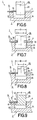
- FIGS. 6, 7 and 8 show an adjusting pin of an adjusting device of a further recording and reproducing device according to the invention in a manner analogous to FIGS. 6, 7 and 8, the adjusting pin having a rectangular or square cross section and having an extension projecting laterally from it in the region of its free end .
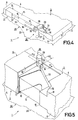
- the formation of the through opening 10 in the area of the ceiling wall 4 is discussed in more detail below with reference to FIGS. 4 and 5.
- the device 1 for receiving a cassette 2 has a cassette receiving device 20 which is attached to a drawer 21 which can be pushed out of the device 1 and retracted into the device 1.
- the cassette receiving device 20 is essentially trough-shaped and has a bottom wall 22 and side walls, of which a side wall 23 and a further side wall 24 are visible in FIG.
- a through opening 25 is provided in the side wall 24, in the area of which the side wall 6 of a cassette 2 provided with the through openings 10, 11 and 12 comes to rest when the cassette 2 is inserted into the cassette receiving device 20.
- the above-mentioned magnetic head and the pressure rollers can be brought into operative connection with the magnetic tape 13 in the cassette 2 through the through opening 25 in the side wall 24 of the cassette receiving device 20.
- a cassette 2 can be inserted into the cassette receiving device 20, which has to be done in such a way that the side wall 6 of the housing 3 of the cassette 2 is opposite the side wall 24 of the cassette receiving device 20 .
- the drawer 21 can be drawn into the device 1 in a manner not shown and described.
- the adjusting device 26, which is shown schematically in FIG. 4, comes into operative connection with the U-shaped closure part 14 of the cassette 2.
- the adjusting device 26 essentially consists of a lever 28 which is pivotably mounted on the bottom wall 22 of the cassette receiving device 20 by means of a shaft 27 and which forms a carrier part for an adjusting pin 29 of the adjusting device 26.
- the adjusting pin 29 protrudes from the lever 28 at one end in a direction of repulsion which is perpendicular to the lever 28 and thus parallel to the axis of the shaft 27 and perpendicular to the top wall 4 of the housing 3 of the cassette 2 is aligned.
- the adjustment pin 29 can be brought into engagement with the U-shaped closure part 14 of the cassette 2 and the adjustment pin 29 controls its adjustment between its closed position and its open position when there is a relative movement between it and the U-shaped closure part 14 transverse to its repelling direction is still received.
- the adjusting pin 29 is of simple cylindrical design with a continuously smooth outer surface, which corresponds to the currently known prior art.
- a mechanical control device (also not shown) attached to the device 1 acts on the control pin 30 and can be used to control the actuation of the adjusting spring which also acts on the control pin 30. Since these details are not essential in the present context, they are not shown for the sake of simplicity.
- the adjusting pin 29 reaches the end of the wall section 33, after which the adjusting pin 29 slides under the action of the adjusting spring acting on the control pin 30 along a wall section 34 running perpendicular to the side wall 6 and delimiting the through opening 10.
- This adjustment of the adjustment pin 29 takes place until the adjustment pin 29 comes to rest on the wall section 35 which runs parallel to the side wall 6 and delimits the through opening 10.
- the adjusting pin 29 being held under the force of the return spring 14 acting on the U-shaped closure part 14 by the first leg part 15 of the U-shaped closure part 14 against the wall section 34 extending perpendicular to the side wall 6 , as shown in Figures 4 and 5, but also in Fig. 6.
- FIG. 7 Embodiment of the invention with an adjusting device 26 for adjusting a closure part 14, the adjusting pin 29 of the adjusting device 26 is provided with two steps 36 and 37 which extend essentially transversely to its direction of repulsion. As also shown in FIG. 7, when the closure part 14 is controlled by the adjustment pin 29 into its open position, the closure part 14 engages with a portion thereof, namely with the first leg part 15, the gradations 36 and 37 of the adjustment pin 29.
- the first one blocks Leg part 15 of the closure part 14, the adjusting pin 29 in a form-fitting manner against an adjustment thereof parallel to its direction of repulsion.
- the gradations 36 and 37 are each formed by an axial delimitation area of a recess 38 in the cylindrical adjusting pin 29.
- the adjusting pin 29 has a diameter D and the depth t of the recess 38 is selected such that the distance d between the contact generator of the adjusting pin 29 abutting the wall section 34 and the diametrically opposite bottom generator of the recess 38, which produces the contact, at which the free End of the first leg part 15 of the closure part 14 rests, the same size as the diameter d of the adjusting pin 29 of the adjusting device 26 of the device according to FIGS. 1, 4, 5 and 6.
- the closure part 14 of the cassette 2 in its open position assumes the same position with respect to the wall section 34 as is also the case with the device according to FIGS. 1, 4, 5 and 6 .
- the adjusting pin 29 of the adjusting device 26 has only a gradation 36 which extends essentially transversely to its direction of repulsion, which in this case has a larger axial area than that of the adjusting pin 29 Diameter having cylindrical end portion 39 of the adjusting pin 29 is formed.
- the invention has been described above with reference to devices for magnetic tape cassettes. However, the invention can also be used for devices for other cassettes, for example for cassettes which contain an optically or magnetically scannable circular disk-shaped recording carrier. Furthermore, the invention can also be applied to devices which have a differently configured adjustment device, for example to devices such as those disclosed in EP 0 438 144 A2 or in EP O 248 908 A1.
Landscapes
- Feeding And Guiding Record Carriers (AREA)
- Automatic Tape Cassette Changers (AREA)
Applications Claiming Priority (2)
| Application Number | Priority Date | Filing Date | Title |
|---|---|---|---|
| AT1106/92 | 1992-05-27 | ||
| AT0110692A AT397738B (de) | 1992-05-27 | 1992-05-27 | Aufzeichnungs- und/oder wiedergabegerät für eine einen aufzeichnungsträger enthaltende kassette |
Publications (3)
| Publication Number | Publication Date |
|---|---|
| EP0572073A2 true EP0572073A2 (fr) | 1993-12-01 |
| EP0572073A3 EP0572073A3 (fr) | 1995-07-26 |
| EP0572073B1 EP0572073B1 (fr) | 1997-08-20 |
Family
ID=3506719
Family Applications (1)
| Application Number | Title | Priority Date | Filing Date |
|---|---|---|---|
| EP93201442A Expired - Lifetime EP0572073B1 (fr) | 1992-05-27 | 1993-05-19 | Appareil d'enregistrement et/ou de reproduction pour une cassette comportant un support d'enregistrement |
Country Status (6)
| Country | Link |
|---|---|
| EP (1) | EP0572073B1 (fr) |
| JP (1) | JPH0668129U (fr) |
| KR (1) | KR930026349U (fr) |
| AT (1) | AT397738B (fr) |
| DE (1) | DE59307147D1 (fr) |
| SG (1) | SG48198A1 (fr) |
Family Cites Families (6)
| Publication number | Priority date | Publication date | Assignee | Title |
|---|---|---|---|---|
| JPH0240626Y2 (fr) * | 1984-10-26 | 1990-10-30 | ||
| JPS63244358A (ja) * | 1987-03-30 | 1988-10-11 | Matsushita Electric Ind Co Ltd | カセツト装着装置 |
| YU123090A (sh) * | 1989-07-03 | 1994-04-05 | N.V. Philips Gloelampenfabrieken | Sistem za snemanje/reprodukcijo signalov na/s magnetnega traku v kaseti |
| US5161079A (en) * | 1990-01-19 | 1992-11-03 | Matsushita Electric Industrial Co., Ltd. | Tape cassette with slidable shutter |
| JP2630004B2 (ja) * | 1990-02-26 | 1997-07-16 | 松下電器産業株式会社 | テープカセット装着装置 |
| JPH05182313A (ja) * | 1991-12-27 | 1993-07-23 | Matsushita Electric Ind Co Ltd | テープレコーダ |
-
1992
- 1992-05-27 AT AT0110692A patent/AT397738B/de not_active IP Right Cessation
-
1993
- 1993-05-14 KR KR2019930008036U patent/KR930026349U/ko not_active Withdrawn
- 1993-05-19 EP EP93201442A patent/EP0572073B1/fr not_active Expired - Lifetime
- 1993-05-19 DE DE59307147T patent/DE59307147D1/de not_active Expired - Fee Related
- 1993-05-19 SG SG1996007830A patent/SG48198A1/en unknown
- 1993-07-07 JP JP037162U patent/JPH0668129U/ja active Pending
Also Published As
| Publication number | Publication date |
|---|---|
| JPH0668129U (ja) | 1994-09-22 |
| KR930026349U (ko) | 1993-12-28 |
| AT397738B (de) | 1994-06-27 |
| EP0572073A3 (fr) | 1995-07-26 |
| ATA110692A (de) | 1993-10-15 |
| SG48198A1 (en) | 1998-04-17 |
| EP0572073B1 (fr) | 1997-08-20 |
| DE59307147D1 (de) | 1997-09-25 |
Similar Documents
| Publication | Publication Date | Title |
|---|---|---|
| DE3007948C2 (de) | Kassette für einen bandförmigen Aufzeichnungsträger | |
| DE3326177C2 (de) | Plattenladevorrichtung | |
| DE3322638C2 (fr) | ||
| EP0922821A2 (fr) | Dispositif d'ouverture de porte | |
| DE4231574C2 (de) | Ladevorrichtung für Bandkassetten | |
| DE2921613A1 (de) | Zuhaltevorrichtung fuer eine tuer o.dgl. | |
| DE2823422A1 (de) | Vorrichtung zum einruecken und wiederausruecken von gedruckten schaltkarten | |
| DE29507538U1 (de) | Kasten zum Schutz gegen Ladendiebstähle mit kompakter Schließvorrichtung, die durch Einwirkung eines Magneten kombiniert mit einer mechanischen Betätigung geöffnet werden kann | |
| DE19514154A1 (de) | Federsperrvorrichtung | |
| EP0074148A2 (fr) | Appareil d'enregistrement et/ou de reproduction | |
| DE69816018T2 (de) | Cassette mit mindestens einer axial bewegbaren spule und einer vorrichtung zur blockierung der axialen bewegung dieser spule | |
| DE69325318T2 (de) | Bandkassette | |
| DE3626941C2 (fr) | ||
| DE4011722A1 (de) | Schliessvorrichtung | |
| DE3112845A1 (de) | Verriegelungseinrichtung fuer eine magnetbandkassette in einem magnetbandgeraet | |
| EP0572073B1 (fr) | Appareil d'enregistrement et/ou de reproduction pour une cassette comportant un support d'enregistrement | |
| DE69610943T2 (de) | Lagerungsbehälter für Magnetbandkassette | |
| DE4205038C2 (de) | Vorrichtung zum Verriegeln und Entriegeln eines Paares von in einer Kassette enthaltenen Bandspulen | |
| DE69308344T2 (de) | Reibungsdämpfer | |
| EP3821507B1 (fr) | Dispositif de décharge de surpression | |
| DE3009703A1 (de) | Verriegelungsmechanismus fuer ein bandabspielgeraet | |
| EP0480515B1 (fr) | Cassette pour un support d'enregistrement | |
| DE69321779T2 (de) | Einrichtung zum Aufzeichnen/Wiedergeben von Signalen | |
| DE2511063C3 (de) | Münzkassette mit durch Verschlußkörper abdeckbarer Münzeinwurföffnung | |
| EP0349005A1 (fr) | Charnière |
Legal Events
| Date | Code | Title | Description |
|---|---|---|---|
| PUAI | Public reference made under article 153(3) epc to a published international application that has entered the european phase |
Free format text: ORIGINAL CODE: 0009012 |
|
| AK | Designated contracting states |
Kind code of ref document: A2 Designated state(s): DE ES FR GB IT |
|
| RAP1 | Party data changed (applicant data changed or rights of an application transferred) |
Owner name: N.V. PHILIPS' GLOEILAMPENFABRIEKEN |
|
| PUAL | Search report despatched |
Free format text: ORIGINAL CODE: 0009013 |
|
| AK | Designated contracting states |
Kind code of ref document: A3 Designated state(s): DE ES FR GB IT |
|
| RAP1 | Party data changed (applicant data changed or rights of an application transferred) |
Owner name: N.V. PHILIPS' GLOEILAMPENFABRIEKEN |
|
| 17P | Request for examination filed |
Effective date: 19960126 |
|
| GRAG | Despatch of communication of intention to grant |
Free format text: ORIGINAL CODE: EPIDOS AGRA |
|
| 17Q | First examination report despatched |
Effective date: 19961106 |
|
| GRAH | Despatch of communication of intention to grant a patent |
Free format text: ORIGINAL CODE: EPIDOS IGRA |
|
| GRAH | Despatch of communication of intention to grant a patent |
Free format text: ORIGINAL CODE: EPIDOS IGRA |
|
| GRAA | (expected) grant |
Free format text: ORIGINAL CODE: 0009210 |
|
| AK | Designated contracting states |
Kind code of ref document: B1 Designated state(s): DE ES FR GB IT |
|
| PG25 | Lapsed in a contracting state [announced via postgrant information from national office to epo] |
Ref country code: IT Free format text: LAPSE BECAUSE OF FAILURE TO SUBMIT A TRANSLATION OF THE DESCRIPTION OR TO PAY THE FEE WITHIN THE PRESCRIBED TIME-LIMIT;WARNING: LAPSES OF ITALIAN PATENTS WITH EFFECTIVE DATE BEFORE 2007 MAY HAVE OCCURRED AT ANY TIME BEFORE 2007. THE CORRECT EFFECTIVE DATE MAY BE DIFFERENT FROM THE ONE RECORDED. Effective date: 19970820 Ref country code: ES Free format text: THE PATENT HAS BEEN ANNULLED BY A DECISION OF A NATIONAL AUTHORITY Effective date: 19970820 |
|
| REF | Corresponds to: |
Ref document number: 59307147 Country of ref document: DE Date of ref document: 19970925 |
|
| GBT | Gb: translation of ep patent filed (gb section 77(6)(a)/1977) |
Effective date: 19971017 |
|
| ET | Fr: translation filed | ||
| PGFP | Annual fee paid to national office [announced via postgrant information from national office to epo] |
Ref country code: GB Payment date: 19980501 Year of fee payment: 6 |
|
| PGFP | Annual fee paid to national office [announced via postgrant information from national office to epo] |
Ref country code: FR Payment date: 19980519 Year of fee payment: 6 |
|
| PLBE | No opposition filed within time limit |
Free format text: ORIGINAL CODE: 0009261 |
|
| STAA | Information on the status of an ep patent application or granted ep patent |
Free format text: STATUS: NO OPPOSITION FILED WITHIN TIME LIMIT |
|
| PGFP | Annual fee paid to national office [announced via postgrant information from national office to epo] |
Ref country code: DE Payment date: 19980724 Year of fee payment: 6 |
|
| 26N | No opposition filed | ||
| REG | Reference to a national code |
Ref country code: FR Ref legal event code: CD |
|
| PG25 | Lapsed in a contracting state [announced via postgrant information from national office to epo] |
Ref country code: GB Free format text: LAPSE BECAUSE OF NON-PAYMENT OF DUE FEES Effective date: 19990519 |
|
| GBPC | Gb: european patent ceased through non-payment of renewal fee |
Effective date: 19990519 |
|
| PG25 | Lapsed in a contracting state [announced via postgrant information from national office to epo] |
Ref country code: FR Free format text: LAPSE BECAUSE OF NON-PAYMENT OF DUE FEES Effective date: 20000131 |
|
| PG25 | Lapsed in a contracting state [announced via postgrant information from national office to epo] |
Ref country code: DE Free format text: LAPSE BECAUSE OF NON-PAYMENT OF DUE FEES Effective date: 20000301 |
|
| REG | Reference to a national code |
Ref country code: FR Ref legal event code: ST |