EP3821507B1 - Dispositif de décharge de surpression - Google Patents
Dispositif de décharge de surpression Download PDFInfo
- Publication number
- EP3821507B1 EP3821507B1 EP19769022.5A EP19769022A EP3821507B1 EP 3821507 B1 EP3821507 B1 EP 3821507B1 EP 19769022 A EP19769022 A EP 19769022A EP 3821507 B1 EP3821507 B1 EP 3821507B1
- Authority
- EP
- European Patent Office
- Prior art keywords
- pressure
- conducting device
- closure
- retaining element
- conducting
- Prior art date
- Legal status (The legal status is an assumption and is not a legal conclusion. Google has not performed a legal analysis and makes no representation as to the accuracy of the status listed.)
- Active
Links
Images

Classifications
-
- H—ELECTRICITY
- H02—GENERATION; CONVERSION OR DISTRIBUTION OF ELECTRIC POWER
- H02B—BOARDS, SUBSTATIONS OR SWITCHING ARRANGEMENTS FOR THE SUPPLY OR DISTRIBUTION OF ELECTRIC POWER
- H02B13/00—Arrangement of switchgear in which switches are enclosed in, or structurally associated with, a casing, e.g. cubicle
- H02B13/02—Arrangement of switchgear in which switches are enclosed in, or structurally associated with, a casing, e.g. cubicle with metal casing
- H02B13/025—Safety arrangements, e.g. in case of excessive pressure or fire due to electrical defect
Definitions
- the invention relates to a pressure relief device, in particular a pressure relief device for medium and/or high voltage systems, such as switchgear.
- systems for medium and/or high voltages in particular switchgear, have pressure relief ducts whose outlet, i.e. the potential gas escape area, is closed in such a way that there is a sufficient opening for pressure relief in the case of overpressure in the medium and/or high voltage system , or is created.
- This is achieved, for example, by predetermined breaking points, such as perforated sheet metal parts and/or bendable sheets or flaps.
- the potential gas escape area should be closed.
- the pressure-guiding device is a pressure-relief duct, in particular a modular pressure-relief duct, and the pressure-guiding device closure is formed by a flap.
- the rotation of the pressure control device lock can be brought about by gravity and/or an overpressure in the pressure control device.
- the force of gravity is therefore sufficient to cause the pressure guide device lock to rotate as soon as the locking elements and the locking mediators no longer interact in such a way that the rotation of the pressure guide device lock is prevented.
- the rotation can also be brought about by an overpressure in the pressure-guiding device.
- the overpressure is generated, for example, by or in the event of an accident, in particular an accidental arc in a medium-voltage and/or high-voltage system.
- the force of gravity is also used here in general to define the terms above and below, i.e. below is the direction in which the force of gravity acts, above is the direction opposite to the direction of the effect of gravity.
- the pressure guide device further comprises one or more rotation limiters, wherein the rotation limiter or limiters limit possible rotation of the pressure guide device closure relative to the pressure guide device between the transition position and the second position.
- the rotation limiter or limiters limit a possible rotation of the pressure-guiding device closure relative to the pressure-guiding device between the transition position and the second position by cooperating with the locking mediators.
- the rotational movement is thus terminated in that the blocking mediator is prevented from further movement in the direction of movement by the rotation limiter.
- the displacement of the pressure-guiding device lock relative to the pressure-guiding device along the direction of pressure propagation can be brought about by an overpressure, in particular by an overpressure that is produced by an arc.
- the pressure guiding device has a holding element guide, in which a holding element engages in the first position, wherein between the first position and the transition position the holding element partially engages in the holding element guide and when the transition position is reached the holding element leaves the holding element guide, so that a Rotation of the pressure-guiding device closure relative to the pressure-guiding device, in particular by one or more, particularly preferably two, receiving elements is no longer prevented.
- a stall force is overcome when transferring the pressure-guiding device closure from the first position to the transition position must or will, which acts between the holding element and the holding element guide. This further secures the pressure control device lock against unintentional opening.
- the stationary force to be overcome can be generated by a clamping device, for example for effecting a non-positive connection, and/or a magnetic holder.
- the magnet mount is formed from one or more permanent magnets and one or more magnet elements, wherein the one or more permanent magnets interact with the magnet elements in the first position and either the permanent magnet or magnets on the holder element guide and the magnet elements on are arranged on the holding element or the permanent magnets are arranged on the holding element and the magnetic elements are arranged on the holding element guide.
- the permanent magnets extend partially or completely over a surface of the holding element guide.
- the magnet elements are formed by a ferromagnetic or paramagnetic holding element.
- the magnetic elements are formed by a ferromagnetically or paramagnetically designed holding element guide and the permanent magnets extend partially or completely over a surface of the holding element or adjoin the holding element.
- the holding element contains a paramagnetic material and the permanent magnets adjoin the holding element.
- a further exemplary embodiment relates to a medium and/or high voltage system, in particular a switchgear for medium and/or high voltages, with a pressure relief device according to one or more of the above statements.
- Another embodiment relates to a method for operating a pressure relief device according to one or more of the above statements, wherein in the event of overpressure in the pressure relief device, the pressure guide device closure is moved by the overpressure along the pressure propagation direction relative to the pressure guide device from the first position to a transitional position and further caused by gravity and the overpressure in the pressure relief device of the pressure control device closure in a rotation of the pressure control device closure relative to the pressure control device, whereby the pressure control device closure or gas outlet areas are no longer closed.
- Another embodiment relates to a method for operating a medium and/or high voltage system, in particular a switchgear for medium and/or high voltages, with a pressure relief device according to one or more of the above, in the event of an overpressure in the pressure relief device, the pressure guide device closure is moved by the overpressure along the pressure propagation direction relative to the pressure guide device from the first position to a transitional position and further by gravity and the overpressure in the pressure relief device the pressure guide device closure in a rotation of the pressure guide device closure relative to the Pressure guide device is offset, whereby the pressure guide device closure the gas outlet area(s) are no longer closed.
- Another embodiment relates to a medium-voltage switchgear or high-voltage switchgear with a pressure relief device according to one or more of the above statements.
- the figure 1 shows a perspective view of a schematic representation of a pressure relief device 1 according to the invention with a pressure control device 100 and a pressure control device closure 200 on one side.
- the pressure-guiding device closure 200 is in a first position 10 on the pressure-guiding device 100 and thus closes the pressure-guiding device 100 on the open side on which it is arranged.
- the pressure guiding device 100 here has two side faces, of which a first side face 120 is visible, and a visible top side 110 and a bottom side, not shown.
- the non-visible side which is opposite the side closed by the pressure control device closure 200, is open here and serves as an inlet into the pressure control device 100 of the pressure relief device 1.
- the inlet can also be on the top 110 and/or on the underside, not shown, and/or be arranged on the first side face 120 and/or the second side face 122 (not shown).
- the figure 2 shows a perspective view of a schematic representation of a pressure relief device 1 according to the invention with a pressure control device 100 and a pressure control device closure 200 on one side.
- the pressure duct shutter 200 is in a second position 20 on the pressure duct 100 and thus does not occlude the pressure duct 100 on the side on which it is located.
- the pressure control device 100 here has two side surfaces, a first side surface 120 and a second side surface 122, and an upper side 110 and a lower side 112.
- a gas inlet area 102 and a gas outlet area 104 are also identified, with the gas outlet area 104 having the pressure control device closure 200 is lockable.
- the pressure-guiding device closure 200 is movably fastened or arranged on the pressure-guiding device 100 with two fastening elements 230 .
- a cover 124 for the fastener 230 serves to hold the fasteners 230 and also improves stability and mountability.
- the pressure guide device lock 200 has a holding element 210 which can engage in the holding element guide 160
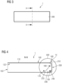
- the figure 3 shows a schematic front view of a pressure relief device 1 according to the invention with a pressure-guiding device closure 200.
- the sectional view of FIG figure 4 been created.
- the figure 4 shows a sectional view of the schematic front view of figure 3 in a transitional position 15, in which the pressure-guiding device lock 200 is pushed away from the blocking element 170 along a pressure propagation direction 1510 in such a way that the locking element 170 no longer causes a rotational movement of the pressure-guiding device lock 200 about a receiving element 150, or a receiving element 150 on each side, by blocking a locking agent 235 prevented.
- the locking device 235 is formed here by an extension of the fastening element 230, which also accommodates the counterpart receiving element 240, which on the one hand allows displacement along the pressure propagation direction 1510 away from the receiving element 150 or towards the receiving element 150 and on the other hand also allows the pressure-guiding device closure 200 to rotate about a receiving element 150 allows.
- the mating female member 240 is an elongated hole. Is shown in the sectional view figure 4 only the fastening element 230 which is arranged on the second side surface 122; an analogous structure can also be found on the first side surface 120, like that figure 2 can be seen.
- the other parts arranged on the second side surface 122 are preferably also located on the first side surface 120 of the pressure-guiding device 100.
- the second side face 122 preferably also has a rotation limiter 180, which serves as a stop for the locking mechanism and thus limits the rotation of the pressure-guiding device closure 200 about the receiving elements 150.
- FIG. 4 shows the figure 4 a preferred embodiment of the pressure-guiding device 100, in which the upper side 110 of the pressure-guiding device 100 has a holding element receptacle 150 which is designed to accommodate a holding element 210, here the upper bent edge of the pressure-guiding device closure 200 in such a way that the holding element 210 can be accommodated in a form-fitting manner in the holding-element guide 160 and in a further preferred embodiment, the displacement of the pressure-guiding device closure 200 away from the receiving element 150 or towards the receiving element 150 is also made more difficult by a non-positive fit. This can happen, for example, via a clamping effect, but also through a magnetic interaction, which is possibly generated by additional elements of a magnet holder.
- the locking element 170 is no longer preventing the blocking mediator 235 from rotating, and the holding element 210 has also left the holding element guide 160, so that the guide does not prevent and/or impede rotation, nor is a force exerted it opposes by clamping or magnetic interaction, displacement or rotation.
- Circle 500 marks the area shown in the following figures, albeit in different positions.
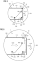
- the figure 5 shows a detail enlargement 501 of circle 500 from FIG figure 4 similar to a schematic sectional view figure 4 in a first position 10.
- the pressure relief device 1 is closed. That is, the pressure guide device shutter 200 has an opening in figure 2 gas outlet region 104 shown, on which pressure control device 100 is closed.
- the holding element 210 of the pressure guiding device closure 200 engages in the holding element guide 160 and is additionally held there, more preferably by clamping or magnetic interaction.
- the holding element guide 160 is here a Y-shaped opening in or arranged on the top 110 of the pressure guide device 100, but can also be arranged on a side surface or the underside of the pressure guide device 100 or several of the indicated locations.
- the locking element 170 prevents, blocks, in the first position, rotation of the pressure guide device lock 200 about the receiving element 150 since the locking mediator 235, on the fastening element 230, is restricted by the locking element 170 from movement other than lateral movement.
- the fastening element 230 is suspended from a receiving element 150, the receiving element 150 here engaging in the receiving counterpart element 240, here a slot in the fastening element 230.
- the rotation limiter 180 is preferably used here as an additional stop for the fastening element 230.
- the arrow 1110 indicates the possible direction of movement of the pressure guide device lock 200 in the event of an overpressure, namely a movement which first causes a lateral displacement of the pressure guide device lock 200 and then a rotation of the pressure guide device lock 200 around that Pickup element 150.
- the figure 6 shows a detail enlargement 502 of a schematic sectional image analogous to that of FIG figure 4 in a transition position 15.
- a pressure wave in the direction of the pressure propagation direction 1510 has pushed the pressure-guiding device lock 200 laterally away from the blocking element 170, so that the locking element 170 no longer causes a rotational movement of the pressure-guiding device lock 200 about a receiving element 150, or one receiving element 150 on each side, by blockage a blocking agent 235 is prevented.
- the blocking agent 235 is here by an extension of the fastener 230, which also houses the female counterpart element 240, which on the one hand allows the lateral displacement away from the female element 150 or towards the female element 150 and on the other hand also allows the rotation of the pressure guide device closure 200 about a female element 150.
- the mating female member 240 is an elongated hole.
- the first side surface 120 and/or the second side surface 122 also has a rotation limiter 180 which serves as a stop for the locking mediator and thus limits the rotation of the pressure guide device closure 200 about the receiving elements 150 .
- the arrow 1110 indicates the direction of the possible movements, with a further lateral movement of the pressure guide device closure 200 here being limited by the abutment of the receiving element 150 against an edge of the receiving counterpart element 240 .
- the locking element 170 is no longer preventing the blocking mediator 235 from rotating, and the holding element 210 has also left the holding element guide 160, so that the guide does not prevent and/or impede rotation, nor is a force exerted it resists, by clamping or magnetic interaction, lateral or rotational movement.
- the upper side 110 of the pressure guiding device 100 is formed completely or in the area of the pressure guiding device closure 200 from two or more parts, for example from a first upper side plate 111 and a second upper side plate 112.
- the first top panel 111 and the second top panel 112 are designed such that either, as shown, the second top panel 112 has a bend and so the first top panel 111 and the second top panel 112 form the holding element guide 160 or alternatively, not shown here, the Bending also have the first top panel 111 or the first top panel 111 and the second top panel 112 to form the holding element guide 160 .
- the holding element guide 160 can alternatively or additionally, not shown here, be arranged on a first side surface 120 and/or a second side surface 122 and/or an underside 115 of the pressure guiding device 100.
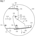
- the figure 7 shows a detail enlargement 503 of a schematic sectional image in a similar way figure 4 in a second position 20 of the pressure control device closure 200.
- the pressure control device closure 200 is in the second position 20 on the pressure control device 100 and thus does not close the pressure control device 100 on the side on which it is arranged, i.e. the gas outlet area 104 is largely free, i.e open.
- the gas outlet region 104 is therefore not or not significantly restricted by the pressure control device closure 200 in the second position 20, ie reduced.
- the pressure-guiding device closure 200 is movably attached or arranged on the pressure-guiding device 100 with two fastening elements 230, one of which is shown.
- a pressure wave in the direction of the pressure propagation direction 1510 pushed the pressure guide device lock 200 laterally away from the locking element 170 so that the locking element 170, a rotational movement of the pressure-guiding device closure 200 about a receiving element 150, or a receiving element 150 on each side, is no longer prevented by blocking a locking mechanism 235, and the pressure-guiding device closure 200 is folded away from the gas outlet region 104 as a result of a downward rotation, i.e. in the direction of gravity 400 , so that a pressure wave can move out of the gas outlet region 104 in the direction of the pressure propagation direction 1510 .
- the rotation limiter 180 prevents further rotation of the pressure guide device lock 200 by the rotation limiter 180 serving as a stop for the locking mediator 235 .
- the pressure guide device lock 200 has rotated about the female member 150 with the female member member 240 .
- the rotation of the pressure-guiding device closure 200 is thus brought about by the force of gravity 400 and/or an overpressure in the pressure-guiding device, characterized by the arrow pointing in the direction of pressure propagation 1510.
Landscapes
- Engineering & Computer Science (AREA)
- Power Engineering (AREA)
- Safety Valves (AREA)
Claims (14)
- Dispositif (1) de détente de la pression d'une installation de coupure pour la moyenne tension et/ou la haute tension, comprenant un dispositif (100) de conduite de la pression, dans lequel le dispositif (100) de conduite de la pression a une ou plusieurs parties (102) d'entrée de gaz et une ou plusieurs parties (104) de sortie de gaz et une fermeture (200) du dispositif de conduite de la pression, dans lequel la fermeture (200) du dispositif de conduite de la pression ferme dans une première position (10) le dispositif (100) de conduite de la pression et ainsi la ou les parties (104) de sortie de gaz et dans lequel la fermeture (200) du dispositif de conduite de la pression ne ferme pas dans une deuxième position (20) le dispositif (100) de conduite de la pression et ainsi la ou les parties (104) de sortie de gaz,
dans lequelle dispositif (100) de conduite de la pression a- un ou plusieurs éléments (150) de réception,- et un ou plusieurs éléments (170) d'arrêt,dans lequella fermeture (200) du dispositif de conduite de la pression a un ou plusieurs éléments (230) de fixation et un ou plusieurs intermédiaires (235) d'arrêt, dans lequel le un ou les éléments (230) de fixation ont chacun un élément (240) de pièce antagoniste de réception, caractérisé en ce quel'élément (240) de pièce antagoniste de réception et l'élément (150) respectif de réception sont reliés de manière à ce que la fermeture (200) du dispositif de conduite de la pression soit reliée de manière mobile au dispositif (100) de conduite de la pression et de manière à ce que la fermeture (200) du dispositif de conduite de la pression puisse être montée de manière coulissante ou tournante par rapport au dispositif (100) de conduite de la pression le long d'une direction (1510) de propagation de la pression,en ce que le ou les éléments (170) d'arrêt empêchent avec les éléments (235) intermédiaires d'arrêt dans la première position (10) une rotation de la fermeture (200) du dispositif de conduite de pression par rapport au dispositif (100) de conduite de la pression et, en commençant par une position (15) transitoire jusqu'à et y compris la deuxième position (20), autorise une rotation de la fermeture (200) du dispositif de conduite de la pression par rapport au dispositif (100) de conduite de la pression,dans lequel le passage de la fermeture (200) du dispositif de conduite de la pression de la première position (10) à la position (15) transitoire peut être provoquée par le déplacement de la fermeture (200) du dispositif de conduite de la pression par rapport au dispositif (100) de conduite de la pression et est libéré par l'élément (170) d'arrêt par le passage de la fermeture (200) du dispositif de conduite de la pression de la première position (10) dans celle de la position (15) transitoire de l'intermédiaire (235) d'arrêt. - Dispositif (1) de détente de la pression suivant la revendication 1,
caractérisé en ce que
la rotation de la fermeture (200) du dispositif de conduite de la pression peut être provoquée par une force (400) de gravité et/ou par une surpression dans le dispositif de conduite de la pression. - Dispositif (1) de détente de la pression suivant la revendication 1 ou 2,
caractérisé en ce que
le dispositif (100) de conduite de la pression a en outre un ou plusieurs limiteurs (180) de rotation, dans lequel le un ou les limiteurs (180) de rotation limitent une rotation possible de la fermeture (200) du dispositif de conduite de la pression par rapport au dispositif (100) de conduite de la pression entre la position (15) transitoire et la deuxième position (20). - Dispositif (1) de détente de la pression suivant la revendication 3,
caractérisé en ce que
le ou les limiteurs (180) de rotation limitent une rotation possible de la fermeture (200) du dispositif de conduite de la pression par rapport au dispositif (100) de conduite de la pression entre la position (15) transitoire et la deuxième position (20) par une coopération avec les intermédiaires (235) d'arrêt. - Dispositif (1) de détente de la pression suivant l'une des revendications précédentes,
caractérisé en ce que
le déplacement de la fermeture (200) du dispositif de conduite de la pression par rapport au dispositif (100) de conduite de la pression peut être provoqué par une surpression. - Dispositif (1) de détente de la pression suivant l'une des revendications précédentes,
caractérisé en ce que
le dispositif (100) de conduite de la pression a un guidage (160) d'élément de maintien, dans lequel dans la première position (10) un élément (210) de maintien pénètre, dans lequel entre la première position (10) et la position (15) transitoire, l'élément (210) de maintien pénètre en partie dans le guidage (160) de l'élément de maintien et, lorsque la position (15) transitoire est atteinte, l'élément (210) de maintien quitte le guidage (160) de l'élément de maintien de manière à ne plus empêcher une rotation de la fermeture (200) du dispositif de conduite de la pression par rapport au dispositif (100) de conduite de la pression. - Dispositif (1) de détente de la pression suivant la revendication 6,
caractérisé en ce que
lors du passage de la fermeture (200) du dispositif de conduite de la pression de la première position (10) à la position (15) transitoire, doit être surmontée une force de persévérance, qui agit entre l'élément (210) de maintien et le guidage (160) de l'élément de maintien. - Dispositif (1) de détente de la pression suivant la revendication 7,
caractérisé en ce que
la force de persévérance à surmonter peut être produite par un dispositif de serrage et/ou par une fixation par aimant. - Dispositif (1) de détente de la pression suivant la revendication 8,
caractérisé en ce que
la fixation par aimant est formée d'un ou plusieurs aimants permanents et d'un ou plusieurs éléments magnétiques, dans lequel le un ou les plusieurs aimants permanents sont en interaction avec les éléments magnétiques dans la première position (10) et ou bien le ou les aimants permanents sont montés sur le guidage (160) de l'élément de maintien et les éléments magnétiques sur l'élément (210) de maintien ou bien les aimants permanents sont montés sur l'élément (210) de maintien et les éléments magnétiques sur le guidage (160) de l'élément de maintien. - Dispositif (1) de détente de la pression suivant la revendication 9,
caractérisé en ce que
les aimants permanents s'étendent en partie ou complètement sur une surface du guidage (160) de l'élément de maintien. - Dispositif (1) de détente de la pression suivant la revendication 10,
caractérisé en ce que
les éléments magnétiques sont formés par un élément (210) de maintien réalisé ferromagnétiquement ou paramagnétiquement. - Dispositif (1) de détente de la pression suivant la revendication 9,
caractérisé en ce que
les éléments magnétiques sont formés par un guidage (160) de l'élément de maintien réalisé ferromagnétiquement ou paramagnétiquement et les aimants permanents s'étendent en partie ou complètement sur une surface de l'élément (210) de maintien ou sont voisins de l'élément (210) de maintien. - Dispositif (1) de détente de la pression suivant la revendication 12,
caractérisé en ce que
l'élément (210) de maintien contient un matériau paramagnétique et les aimants permanents sont voisins de l'élément (210) de maintien. - Procédé pour faire fonctionner un dispositif (1) de détente de la pression suivant l'une des revendications précédentes,
caractérisé en ce que
dans le cas d'une surpression dans le dispositif (1) de détente de la pression, on fait passer la fermeture (200) du dispositif de conduite de la pression par une surpression par rapport au dispositif (100) de conduite de la pression, de la première position (10) le long d'une direction (1510) de propagation de la pression à une position (15) transitoire et on continue, par une force (400) de gravité et par la surpression dans le dispositif (1) de détente de la pression, à mettre la fermeture (200) du dispositif de conduite de la pression dans une rotation de la fermeture (200) du dispositif de conduite de la pression par rapport au dispositif (100) de conduite de la pression, grâce à quoi la fermeture (200) du dispositif de conduite de la pression ne ferme plus là où les parties (104) de sortie de gaz.
Applications Claiming Priority (2)
| Application Number | Priority Date | Filing Date | Title |
|---|---|---|---|
| DE102018215215.2A DE102018215215B4 (de) | 2018-09-07 | 2018-09-07 | Druckentlastungsvorrichtung und Verfahren zum Betreiben einer Druckentlastungsvorrichtung |
| PCT/EP2019/072665 WO2020048802A1 (fr) | 2018-09-07 | 2019-08-26 | Dispositif de décompression |
Publications (2)
| Publication Number | Publication Date |
|---|---|
| EP3821507A1 EP3821507A1 (fr) | 2021-05-19 |
| EP3821507B1 true EP3821507B1 (fr) | 2023-08-23 |
Family
ID=67956697
Family Applications (1)
| Application Number | Title | Priority Date | Filing Date |
|---|---|---|---|
| EP19769022.5A Active EP3821507B1 (fr) | 2018-09-07 | 2019-08-26 | Dispositif de décharge de surpression |
Country Status (3)
| Country | Link |
|---|---|
| EP (1) | EP3821507B1 (fr) |
| DE (1) | DE102018215215B4 (fr) |
| WO (1) | WO2020048802A1 (fr) |
Cited By (1)
| Publication number | Priority date | Publication date | Assignee | Title |
|---|---|---|---|---|
| EP4712279A1 (fr) * | 2024-09-13 | 2026-03-18 | Abb Schweiz Ag | Appareillage de commutation avec conduit d'air |
Family Cites Families (6)
| Publication number | Priority date | Publication date | Assignee | Title |
|---|---|---|---|---|
| CH324938A (de) | 1954-02-03 | 1957-10-15 | Josef Meyer Eisen Und Waggonba | Verschlusseinrichtung an einem Behälter für brennbare Flüssigkeiten |
| JPS59126507U (ja) * | 1983-02-16 | 1984-08-25 | 株式会社明電舎 | 閉鎖配電盤 |
| DE102009043026B4 (de) | 2009-09-28 | 2012-06-06 | Bernhard Gritzbach | Druckentlastungsklappe |
| JP2012253980A (ja) * | 2011-06-07 | 2012-12-20 | Mitsubishi Electric Corp | スイッチギヤ |
| US9593863B2 (en) * | 2013-11-13 | 2017-03-14 | Eaton Corporation | Vent apparatus for electrical enclosure |
| GB2544999A (en) | 2015-12-03 | 2017-06-07 | General Electric Technology Gmbh | Improvements in or relating to power semiconductor modules |
-
2018
- 2018-09-07 DE DE102018215215.2A patent/DE102018215215B4/de active Active
-
2019
- 2019-08-26 WO PCT/EP2019/072665 patent/WO2020048802A1/fr not_active Ceased
- 2019-08-26 EP EP19769022.5A patent/EP3821507B1/fr active Active
Cited By (1)
| Publication number | Priority date | Publication date | Assignee | Title |
|---|---|---|---|---|
| EP4712279A1 (fr) * | 2024-09-13 | 2026-03-18 | Abb Schweiz Ag | Appareillage de commutation avec conduit d'air |
Also Published As
| Publication number | Publication date |
|---|---|
| WO2020048802A1 (fr) | 2020-03-12 |
| DE102018215215B4 (de) | 2022-10-06 |
| EP3821507A1 (fr) | 2021-05-19 |
| DE102018215215A1 (de) | 2020-03-12 |
Similar Documents
| Publication | Publication Date | Title |
|---|---|---|
| DE69413948T2 (de) | Behälter mit verriegelbarem deckel | |
| DE10123817B4 (de) | Fahrzeugtürgriffvorrichtung | |
| DE2823422A1 (de) | Vorrichtung zum einruecken und wiederausruecken von gedruckten schaltkarten | |
| EP0922821B1 (fr) | Dispositif d'ouverture de porte | |
| EP0606564A1 (fr) | Dispositif de réglage de l'orientation de tiroirs et similaires | |
| DE112007001067T5 (de) | Druck/Druck-Schloss | |
| DE102011103097A1 (de) | Vorrichtung und Verfahren zum lösbaren Befestigen eines Greifers | |
| EP2180121B1 (fr) | Dispositif de fixation d'un capot en position | |
| WO2016177360A1 (fr) | Couvercle de protection pour un boîtier rapporté | |
| DE60107812T2 (de) | Sicherheitsverpackung für warenpräsentation | |
| DE69306683T2 (de) | Wiederverwendbare Befestigung für Trageband | |
| DE102018215215B4 (de) | Druckentlastungsvorrichtung und Verfahren zum Betreiben einer Druckentlastungsvorrichtung | |
| EP0384164A2 (fr) | Dispositif de verrouillage pour orifice de chargement d'unité d'entraînement de disques | |
| EP1914780B1 (fr) | Disjoncteur-sectionneur à fusibles et dispositif de verrouillage pour un disjoncteur-sectionneur à fusibles | |
| DE2019352B2 (de) | Oberwalzen-Trag- und Belastungsvorrichtung | |
| EP2041852B1 (fr) | Interrupteur avec un accouplement pour l'organe de commande | |
| EP4126485B1 (fr) | Dispositif d'aimant commutable | |
| DE102019200066A1 (de) | Lukenanordnung für ein Freizeitfahrzeug | |
| DE69835255T2 (de) | Betätigungsvorrichtung für Lastschalter mit Schalter zum Ausserbetriebsetzen | |
| DE102018105316A1 (de) | Anordnung mit einem in einem Gehäuse angeordneten Kartenleser | |
| DE102012007023A1 (de) | Schlossvorrichtung zum Verhindern einer Kollision | |
| DE3822325C1 (fr) | ||
| DE202015106985U1 (de) | Nutzentrennwerkzeug | |
| EP0460277A2 (fr) | Système de verrouillage pour tiroirs | |
| EP1124298A1 (fr) | Boítier pour appareillage installé sous plancher |
Legal Events
| Date | Code | Title | Description |
|---|---|---|---|
| STAA | Information on the status of an ep patent application or granted ep patent |
Free format text: STATUS: UNKNOWN |
|
| STAA | Information on the status of an ep patent application or granted ep patent |
Free format text: STATUS: THE INTERNATIONAL PUBLICATION HAS BEEN MADE |
|
| PUAI | Public reference made under article 153(3) epc to a published international application that has entered the european phase |
Free format text: ORIGINAL CODE: 0009012 |
|
| STAA | Information on the status of an ep patent application or granted ep patent |
Free format text: STATUS: REQUEST FOR EXAMINATION WAS MADE |
|
| 17P | Request for examination filed |
Effective date: 20210209 |
|
| AK | Designated contracting states |
Kind code of ref document: A1 Designated state(s): AL AT BE BG CH CY CZ DE DK EE ES FI FR GB GR HR HU IE IS IT LI LT LU LV MC MK MT NL NO PL PT RO RS SE SI SK SM TR |
|
| DAV | Request for validation of the european patent (deleted) | ||
| DAX | Request for extension of the european patent (deleted) | ||
| GRAP | Despatch of communication of intention to grant a patent |
Free format text: ORIGINAL CODE: EPIDOSNIGR1 |
|
| STAA | Information on the status of an ep patent application or granted ep patent |
Free format text: STATUS: GRANT OF PATENT IS INTENDED |
|
| INTG | Intention to grant announced |
Effective date: 20230320 |
|
| GRAS | Grant fee paid |
Free format text: ORIGINAL CODE: EPIDOSNIGR3 |
|
| GRAA | (expected) grant |
Free format text: ORIGINAL CODE: 0009210 |
|
| STAA | Information on the status of an ep patent application or granted ep patent |
Free format text: STATUS: THE PATENT HAS BEEN GRANTED |
|
| AK | Designated contracting states |
Kind code of ref document: B1 Designated state(s): AL AT BE BG CH CY CZ DE DK EE ES FI FR GB GR HR HU IE IS IT LI LT LU LV MC MK MT NL NO PL PT RO RS SE SI SK SM TR |
|
| REG | Reference to a national code |
Ref country code: GB Ref legal event code: FG4D Free format text: NOT ENGLISH |
|
| REG | Reference to a national code |
Ref country code: CH Ref legal event code: EP |
|
| REG | Reference to a national code |
Ref country code: DE Ref legal event code: R096 Ref document number: 502019009074 Country of ref document: DE |
|
| REG | Reference to a national code |
Ref country code: IE Ref legal event code: FG4D Free format text: LANGUAGE OF EP DOCUMENT: GERMAN |
|
| REG | Reference to a national code |
Ref country code: LT Ref legal event code: MG9D |
|
| REG | Reference to a national code |
Ref country code: NL Ref legal event code: MP Effective date: 20230823 |
|
| PG25 | Lapsed in a contracting state [announced via postgrant information from national office to epo] |
Ref country code: GR Free format text: LAPSE BECAUSE OF FAILURE TO SUBMIT A TRANSLATION OF THE DESCRIPTION OR TO PAY THE FEE WITHIN THE PRESCRIBED TIME-LIMIT Effective date: 20231124 |
|
| PG25 | Lapsed in a contracting state [announced via postgrant information from national office to epo] |
Ref country code: IS Free format text: LAPSE BECAUSE OF FAILURE TO SUBMIT A TRANSLATION OF THE DESCRIPTION OR TO PAY THE FEE WITHIN THE PRESCRIBED TIME-LIMIT Effective date: 20231223 |
|
| PG25 | Lapsed in a contracting state [announced via postgrant information from national office to epo] |
Ref country code: SE Free format text: LAPSE BECAUSE OF FAILURE TO SUBMIT A TRANSLATION OF THE DESCRIPTION OR TO PAY THE FEE WITHIN THE PRESCRIBED TIME-LIMIT Effective date: 20230823 Ref country code: RS Free format text: LAPSE BECAUSE OF FAILURE TO SUBMIT A TRANSLATION OF THE DESCRIPTION OR TO PAY THE FEE WITHIN THE PRESCRIBED TIME-LIMIT Effective date: 20230823 Ref country code: PT Free format text: LAPSE BECAUSE OF FAILURE TO SUBMIT A TRANSLATION OF THE DESCRIPTION OR TO PAY THE FEE WITHIN THE PRESCRIBED TIME-LIMIT Effective date: 20231226 Ref country code: NO Free format text: LAPSE BECAUSE OF FAILURE TO SUBMIT A TRANSLATION OF THE DESCRIPTION OR TO PAY THE FEE WITHIN THE PRESCRIBED TIME-LIMIT Effective date: 20231123 Ref country code: NL Free format text: LAPSE BECAUSE OF FAILURE TO SUBMIT A TRANSLATION OF THE DESCRIPTION OR TO PAY THE FEE WITHIN THE PRESCRIBED TIME-LIMIT Effective date: 20230823 Ref country code: LV Free format text: LAPSE BECAUSE OF FAILURE TO SUBMIT A TRANSLATION OF THE DESCRIPTION OR TO PAY THE FEE WITHIN THE PRESCRIBED TIME-LIMIT Effective date: 20230823 Ref country code: LT Free format text: LAPSE BECAUSE OF FAILURE TO SUBMIT A TRANSLATION OF THE DESCRIPTION OR TO PAY THE FEE WITHIN THE PRESCRIBED TIME-LIMIT Effective date: 20230823 Ref country code: IS Free format text: LAPSE BECAUSE OF FAILURE TO SUBMIT A TRANSLATION OF THE DESCRIPTION OR TO PAY THE FEE WITHIN THE PRESCRIBED TIME-LIMIT Effective date: 20231223 Ref country code: HR Free format text: LAPSE BECAUSE OF FAILURE TO SUBMIT A TRANSLATION OF THE DESCRIPTION OR TO PAY THE FEE WITHIN THE PRESCRIBED TIME-LIMIT Effective date: 20230823 Ref country code: GR Free format text: LAPSE BECAUSE OF FAILURE TO SUBMIT A TRANSLATION OF THE DESCRIPTION OR TO PAY THE FEE WITHIN THE PRESCRIBED TIME-LIMIT Effective date: 20231124 Ref country code: FI Free format text: LAPSE BECAUSE OF FAILURE TO SUBMIT A TRANSLATION OF THE DESCRIPTION OR TO PAY THE FEE WITHIN THE PRESCRIBED TIME-LIMIT Effective date: 20230823 |
|
| PG25 | Lapsed in a contracting state [announced via postgrant information from national office to epo] |
Ref country code: PL Free format text: LAPSE BECAUSE OF FAILURE TO SUBMIT A TRANSLATION OF THE DESCRIPTION OR TO PAY THE FEE WITHIN THE PRESCRIBED TIME-LIMIT Effective date: 20230823 |
|
| PG25 | Lapsed in a contracting state [announced via postgrant information from national office to epo] |
Ref country code: LU Free format text: LAPSE BECAUSE OF NON-PAYMENT OF DUE FEES Effective date: 20230826 |
|
| PG25 | Lapsed in a contracting state [announced via postgrant information from national office to epo] |
Ref country code: ES Free format text: LAPSE BECAUSE OF FAILURE TO SUBMIT A TRANSLATION OF THE DESCRIPTION OR TO PAY THE FEE WITHIN THE PRESCRIBED TIME-LIMIT Effective date: 20230823 |
|
| PG25 | Lapsed in a contracting state [announced via postgrant information from national office to epo] |
Ref country code: SM Free format text: LAPSE BECAUSE OF FAILURE TO SUBMIT A TRANSLATION OF THE DESCRIPTION OR TO PAY THE FEE WITHIN THE PRESCRIBED TIME-LIMIT Effective date: 20230823 Ref country code: RO Free format text: LAPSE BECAUSE OF FAILURE TO SUBMIT A TRANSLATION OF THE DESCRIPTION OR TO PAY THE FEE WITHIN THE PRESCRIBED TIME-LIMIT Effective date: 20230823 Ref country code: LU Free format text: LAPSE BECAUSE OF NON-PAYMENT OF DUE FEES Effective date: 20230826 Ref country code: ES Free format text: LAPSE BECAUSE OF FAILURE TO SUBMIT A TRANSLATION OF THE DESCRIPTION OR TO PAY THE FEE WITHIN THE PRESCRIBED TIME-LIMIT Effective date: 20230823 Ref country code: EE Free format text: LAPSE BECAUSE OF FAILURE TO SUBMIT A TRANSLATION OF THE DESCRIPTION OR TO PAY THE FEE WITHIN THE PRESCRIBED TIME-LIMIT Effective date: 20230823 Ref country code: DK Free format text: LAPSE BECAUSE OF FAILURE TO SUBMIT A TRANSLATION OF THE DESCRIPTION OR TO PAY THE FEE WITHIN THE PRESCRIBED TIME-LIMIT Effective date: 20230823 Ref country code: CZ Free format text: LAPSE BECAUSE OF FAILURE TO SUBMIT A TRANSLATION OF THE DESCRIPTION OR TO PAY THE FEE WITHIN THE PRESCRIBED TIME-LIMIT Effective date: 20230823 Ref country code: SK Free format text: LAPSE BECAUSE OF FAILURE TO SUBMIT A TRANSLATION OF THE DESCRIPTION OR TO PAY THE FEE WITHIN THE PRESCRIBED TIME-LIMIT Effective date: 20230823 |
|
| REG | Reference to a national code |
Ref country code: BE Ref legal event code: MM Effective date: 20230831 |
|
| REG | Reference to a national code |
Ref country code: IE Ref legal event code: MM4A |
|
| REG | Reference to a national code |
Ref country code: DE Ref legal event code: R097 Ref document number: 502019009074 Country of ref document: DE |
|
| PG25 | Lapsed in a contracting state [announced via postgrant information from national office to epo] |
Ref country code: MC Free format text: LAPSE BECAUSE OF FAILURE TO SUBMIT A TRANSLATION OF THE DESCRIPTION OR TO PAY THE FEE WITHIN THE PRESCRIBED TIME-LIMIT Effective date: 20230823 |
|
| PLBE | No opposition filed within time limit |
Free format text: ORIGINAL CODE: 0009261 |
|
| STAA | Information on the status of an ep patent application or granted ep patent |
Free format text: STATUS: NO OPPOSITION FILED WITHIN TIME LIMIT |
|
| PG25 | Lapsed in a contracting state [announced via postgrant information from national office to epo] |
Ref country code: IE Free format text: LAPSE BECAUSE OF NON-PAYMENT OF DUE FEES Effective date: 20230826 |
|
| GBPC | Gb: european patent ceased through non-payment of renewal fee |
Effective date: 20231123 |
|
| 26N | No opposition filed |
Effective date: 20240524 |
|
| PG25 | Lapsed in a contracting state [announced via postgrant information from national office to epo] |
Ref country code: IE Free format text: LAPSE BECAUSE OF NON-PAYMENT OF DUE FEES Effective date: 20230826 Ref country code: SI Free format text: LAPSE BECAUSE OF FAILURE TO SUBMIT A TRANSLATION OF THE DESCRIPTION OR TO PAY THE FEE WITHIN THE PRESCRIBED TIME-LIMIT Effective date: 20230823 |
|
| PG25 | Lapsed in a contracting state [announced via postgrant information from national office to epo] |
Ref country code: BE Free format text: LAPSE BECAUSE OF NON-PAYMENT OF DUE FEES Effective date: 20230831 |
|
| PG25 | Lapsed in a contracting state [announced via postgrant information from national office to epo] |
Ref country code: GB Free format text: LAPSE BECAUSE OF NON-PAYMENT OF DUE FEES Effective date: 20231123 |
|
| PG25 | Lapsed in a contracting state [announced via postgrant information from national office to epo] |
Ref country code: GB Free format text: LAPSE BECAUSE OF NON-PAYMENT OF DUE FEES Effective date: 20231123 |
|
| PG25 | Lapsed in a contracting state [announced via postgrant information from national office to epo] |
Ref country code: BG Free format text: LAPSE BECAUSE OF FAILURE TO SUBMIT A TRANSLATION OF THE DESCRIPTION OR TO PAY THE FEE WITHIN THE PRESCRIBED TIME-LIMIT Effective date: 20230823 |
|
| PG25 | Lapsed in a contracting state [announced via postgrant information from national office to epo] |
Ref country code: BG Free format text: LAPSE BECAUSE OF FAILURE TO SUBMIT A TRANSLATION OF THE DESCRIPTION OR TO PAY THE FEE WITHIN THE PRESCRIBED TIME-LIMIT Effective date: 20230823 |
|
| PG25 | Lapsed in a contracting state [announced via postgrant information from national office to epo] |
Ref country code: CY Free format text: LAPSE BECAUSE OF FAILURE TO SUBMIT A TRANSLATION OF THE DESCRIPTION OR TO PAY THE FEE WITHIN THE PRESCRIBED TIME-LIMIT; INVALID AB INITIO Effective date: 20190826 |
|
| PG25 | Lapsed in a contracting state [announced via postgrant information from national office to epo] |
Ref country code: HU Free format text: LAPSE BECAUSE OF FAILURE TO SUBMIT A TRANSLATION OF THE DESCRIPTION OR TO PAY THE FEE WITHIN THE PRESCRIBED TIME-LIMIT; INVALID AB INITIO Effective date: 20190826 |
|
| PGFP | Annual fee paid to national office [announced via postgrant information from national office to epo] |
Ref country code: TR Payment date: 20250819 Year of fee payment: 7 Ref country code: IT Payment date: 20250827 Year of fee payment: 7 |
|
| REG | Reference to a national code |
Ref country code: AT Ref legal event code: MM01 Ref document number: 1603700 Country of ref document: AT Kind code of ref document: T Effective date: 20240826 |
|
| PG25 | Lapsed in a contracting state [announced via postgrant information from national office to epo] |
Ref country code: AT Free format text: LAPSE BECAUSE OF NON-PAYMENT OF DUE FEES Effective date: 20240826 |
|
| PGFP | Annual fee paid to national office [announced via postgrant information from national office to epo] |
Ref country code: FR Payment date: 20250827 Year of fee payment: 7 |
|
| REG | Reference to a national code |
Ref country code: CH Ref legal event code: U11 Free format text: ST27 STATUS EVENT CODE: U-0-0-U10-U11 (AS PROVIDED BY THE NATIONAL OFFICE) Effective date: 20251110 |
|
| PGFP | Annual fee paid to national office [announced via postgrant information from national office to epo] |
Ref country code: DE Payment date: 20251020 Year of fee payment: 7 |
|
| PGFP | Annual fee paid to national office [announced via postgrant information from national office to epo] |
Ref country code: CH Payment date: 20251110 Year of fee payment: 7 |
|
| PGFP | Annual fee paid to national office [announced via postgrant information from national office to epo] |
Ref country code: AT Payment date: 20260410 Year of fee payment: 5 |