EP0572221B1 - Empileur à haute capacité pour des enveloppes - Google Patents
Empileur à haute capacité pour des enveloppes Download PDFInfo
- Publication number
- EP0572221B1 EP0572221B1 EP93304049A EP93304049A EP0572221B1 EP 0572221 B1 EP0572221 B1 EP 0572221B1 EP 93304049 A EP93304049 A EP 93304049A EP 93304049 A EP93304049 A EP 93304049A EP 0572221 B1 EP0572221 B1 EP 0572221B1
- Authority
- EP
- European Patent Office
- Prior art keywords
- envelopes
- envelope
- flipper plate
- compartment
- storage compartment
- Prior art date
- Legal status (The legal status is an assumption and is not a legal conclusion. Google has not performed a legal analysis and makes no representation as to the accuracy of the status listed.)
- Expired - Lifetime
Links
Images



Classifications
-
- B—PERFORMING OPERATIONS; TRANSPORTING
- B65—CONVEYING; PACKING; STORING; HANDLING THIN OR FILAMENTARY MATERIAL
- B65H—HANDLING THIN OR FILAMENTARY MATERIAL, e.g. SHEETS, WEBS, CABLES
- B65H29/00—Delivering or advancing articles from machines; Advancing articles to or into piles
- B65H29/38—Delivering or advancing articles from machines; Advancing articles to or into piles by movable piling or advancing arms, frames, plates, or like members with which the articles are maintained in face contact
- B65H29/44—Members oscillated in arcuate paths
-
- B—PERFORMING OPERATIONS; TRANSPORTING
- B65—CONVEYING; PACKING; STORING; HANDLING THIN OR FILAMENTARY MATERIAL
- B65H—HANDLING THIN OR FILAMENTARY MATERIAL, e.g. SHEETS, WEBS, CABLES
- B65H31/00—Pile receivers
- B65H31/04—Pile receivers with movable end support arranged to recede as pile accumulates
- B65H31/06—Pile receivers with movable end support arranged to recede as pile accumulates the articles being piled on edge
-
- B—PERFORMING OPERATIONS; TRANSPORTING
- B65—CONVEYING; PACKING; STORING; HANDLING THIN OR FILAMENTARY MATERIAL
- B65H—HANDLING THIN OR FILAMENTARY MATERIAL, e.g. SHEETS, WEBS, CABLES
- B65H2301/00—Handling processes for sheets or webs
- B65H2301/30—Orientation, displacement, position of the handled material
- B65H2301/33—Modifying, selecting, changing orientation
- B65H2301/332—Turning, overturning
- B65H2301/3321—Turning, overturning kinetic therefor
- B65H2301/33212—Turning, overturning kinetic therefor about an axis parallel to the direction of displacement of material
-
- B—PERFORMING OPERATIONS; TRANSPORTING
- B65—CONVEYING; PACKING; STORING; HANDLING THIN OR FILAMENTARY MATERIAL
- B65H—HANDLING THIN OR FILAMENTARY MATERIAL, e.g. SHEETS, WEBS, CABLES
- B65H2301/00—Handling processes for sheets or webs
- B65H2301/30—Orientation, displacement, position of the handled material
- B65H2301/33—Modifying, selecting, changing orientation
- B65H2301/332—Turning, overturning
- B65H2301/3322—Turning, overturning according to a determined angle
- B65H2301/33222—90°
-
- B—PERFORMING OPERATIONS; TRANSPORTING
- B65—CONVEYING; PACKING; STORING; HANDLING THIN OR FILAMENTARY MATERIAL
- B65H—HANDLING THIN OR FILAMENTARY MATERIAL, e.g. SHEETS, WEBS, CABLES
- B65H2701/00—Handled material; Storage means
- B65H2701/10—Handled articles or webs
- B65H2701/19—Specific article or web
- B65H2701/1916—Envelopes and articles of mail
Definitions
- This invention is directed to a stacker for stacking envelopes received from a machine that has placed images on the envelopes, and more particularly, to an envelope stacking apparatus that stacks envelopes on long edges thereof.
- Simple catch boxes as for example, in FIG. 1, which most low capacity stackers employ, are N - 1 stackers, so that the user must perform a very tedious manual inversion of the envelopes in order to make the envelope printing order match the letter order that must be inserted into the envelopes. Therefore, if possible, the imaged or addressed side of envelopes should be stored 1 to N as shown in FIG. 2.
- GB-A-401,929 discloses a stacking device in which sealed letters are received on a stacking plate with their short edge leading. Periodically, a stop plate halts the flow of letters and the plate is rotated so as to stack the letters accumulated thereon in a storage area with their short edges horizontal and long edges vertical.
- An object of the present invention is to provide a simple and cost effective envelope stacker.
- the present invention provides an envelope stacker according to claim 1 of the appended claims.
- the invention further provides an evelope stacker according to claim 5 of the appended claims
- the invention further provides a printer according to claim 8 of the appended claims.
- the high capacity envelope stacker apparatus 100 of the present invention is used only part of the time an imaging apparatus, such as a printer, is in use. As such, it must be compact and unobtrusive from an appearance standpoint, and since it is not a dedicated part of the imaging apparatus, it must be inexpensive.
- Such an envelope stacker is shown in FIG. 3 as 100 connected to an exemplary printer 30, such as the Xerox 4045®, that includes an envelope feeder 10.
- Envelope feeder 10 is a high capacity (200 envelopes), gravity-fed, load-while-run (when a cover safety interlock is not used) apparatus which is adapted to be connected to a printer with a long dimension of the envelopes 8 placed against the end and short edge dimension of the printer for minimum footprint usage.
- the envelopes are inserted flap down within walls of bin 13.
- a planar bottom and envelope supporting portion of the bin has a relieved portion therein in the shape of an envelope flap that permits the flap of the lowermost envelope to extend thereinto.
- a motor and brackets support a picker blade by way of a shaft (not shown) for back and forth or oscillatory movement within a predetermined space along the bottom surface of bin 13.
- the blade (not shown) is rotated by the motor from a first or home position underlying bin 13 to a second position within printer 30.
- the picker blade sweeps each envelope sideways and pivots them from a short edge dimension to a long edge dimension within the printer between guides 52 and 53.
- Each envelope is then registered along its long edge with scuffer wheel 55 and fed out of the printer by feed rolls 60 into high capacity envelope stacking apparatus 100.
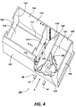
- High capacity envelope stacker 100 of the present invention in FIGS. 3 - 5 accepts envelopes from copier/printer 30 at about a 30° angle and comprises a catch tray having side walls 101 and 102 and end walls 103 and 104 with the catch tray being divided into an envelope receiving compartment 120 and an envelope storage compartment 110.
- the two compartments are separated by a slidable partition 113 and compartment 120 has a bottom shelf 121.
- Brush-like snubbers 118 are positioned on opposite sides of walls 101 and 102 for reasons that will be explained hereinafter.
- a movably pivoting flipper plate 122 is positioned within compartment 120 and mounted by hinge 123 to be rotated through an arc of 90° from a position on top of bottom receiving shelf 121 past snubbers 118 by an actuator disc 125 driven by a motor (not shown).
- Actuator disc 125 is connected to pivoting flipper plate 122 by an eccentrically mounted link 126.
- envelopes exit the output or right end of copier/printer 30 as viewed in FIG. 3, at an angle of approximately 30° in the direction of arrow A of FIG. 4 and are received in receiving compartment 120 and coming to rest on flipper 122.
- Envelopes pass a photosensor 40 in the exit path of copier/printer 30 which includes an emitter 41 and a detector or receiver 42.
- the software of copier/printer 30 is designed such that a signal from sensor 40 that an envelope has passed that station is sent to the onboard computer of the copier/printer. After a predetermined delay, to allow the envelope to come to rest in the stacker on flipper plate 122, a signal is sent from the computer to actuate the motor that turns actuator disc 125 one revolution.
- the resultant stacked envelopes from this operation are stacked (image side) 1 - N which is the desired sequence since copy sheets that are to be inserted into the envelopes are usually stacked 1 - N.
- the advantages of this stacker apparatus over prior envelope stackers include the 1 - N order integrity; low-complexity; low unit manufacturing cost; user friendliness and safe operation.
- FIGS. 6 and 7 An alternative embodiment of the high capacity envelope stacker in accordance with the present invention is shown in FIGS. 6 and 7 in which like numbers represent like elements of FIGS. 3 - 5.
- envelopes 8 enter stacker 150 and rest flap side down on top of flipper plate 122 which is parallel to bottom shelf 153.
- motor pulley 160 is actuated by a signal from the stacker logic circuit (not shown)
- disc 155 is rotated by belt 161 in the direction of arrow D for one revolution for each envelope and pin 156 that is attached to disc 155 lifts flipper plate 122 which is spring loaded down and envelope 8 past brushes 118 onto a long edge thereof and against stopper plate 170.
- the action of flipper plate 122 pushes the envelopes and movable support 154 along rails or tubular slides 111 in the direction of arrows B toward end member 152 and away from end member 151.
- the stacker apparatus of FIG. 7 is the same as that shown in FIG. 6 except that pin 156 is shown captured within a bracket 130 connected to the underside of flipper plate 122. As a result, rotation of disc 155 causes pin 156 to ride within bracket 130 to thereby raise and lower flipper plate 122 in order to stack incoming envelopes.
Landscapes
- Engineering & Computer Science (AREA)
- Mechanical Engineering (AREA)
- Pile Receivers (AREA)
- Sheets, Magazines, And Separation Thereof (AREA)
Claims (8)
- Appareil empileur d'enveloppes comprenant un compartiment (120) de réception destiné à recevoir une pluralité d'enveloppes (8) dont la face portant le volet n'est pas exposée, dont le bord court est en avant, et destiné à supporter les enveloppes dans une première position sensiblement non verticale, et un compartiment (110) de stockage destiné à stocker des enveloppes dans une pile dans une seconde position verticale, la dernière enveloppe de la pile ayant sa face portant le volet exposée ; dans lequel ledit compartiment (120) de réception comporte des moyens (122-126) destinés à déplacer les enveloppes de ladite première position à ladite seconde position ;
caractérisé en ce que lesdits moyens (122-126) de déplacement sont adaptés à déplacer des enveloppes (8) lorsqu'elles sont reçues dans ledit compartiment (120) de réception, de façon à ce que les enveloppes soient empilées individuellement en séquence dans ledit compartiment (110) de stockage, et en ce que, à ladite seconde position, lesdites enveloppes (8) ont leurs bords courts verticaux. - Appareil empileur d'enveloppes selon la revendication 1, comportant des moyens (113) à cloison coulissante destinés à séparer ledit compartiment (120) de réception dudit compartiment (110) de stockage, et dans lequel lesdits moyens (113) à cloison coulissante sont montés sur des rails et adaptés à être repoussés par pas successifs le long desdits rails par lesdits moyens (122-126) destinés à déplacer les enveloppes (8) de ladite première position à ladite seconde position verticale.
- Appareil empileur d'enveloppes selon la revendication 1 ou 2, dans lequel lesdits moyens (122-126) destinés à déplacer les enveloppes (8) de ladite première position à ladite seconde position verticale comportent également une plaque (122) de basculement pivotante, ladite plaque de basculement étant reliée à un disque (125) actionneur de telle façon que chaque tour dudit disque soulève ladite plaque (122) de basculement de ladite première position à une position verticale, ladite plaque de basculement revenant à ladite première position par gravité.
- Empileur d'enveloppes selon la revendication 1, 2 ou 3, dans lequel ledit plateau de réception est adapté à convertir des enveloppes (8) empilées dans celui-ci dans l'ordre N - 1 à l'ordre 1 - N avant qu'elles n'en soient retirées par un opérateur.
- Appareil empileur d'enveloppes comprenant :un plateau (101-104) de réception ;des moyens (113) divisant ledit plateau de réception en un compartiment (120) de réception et un compartiment (110) de stockage, ledit compartiment (120) de réception étant adapté à recevoir des enveloppes (8) par le bord court en avant, et ledit compartiment (110) de stockage étant adapté à recevoir des enveloppes, le bord long en avant ; etdes moyens (122-126) destinés à convertir individuellement et séparément des enveloppes (8) après que chaque enveloppe a été reçue dans ledit compartiment (120) de réception d'une position horizontale initiale à une position sensiblement verticale et à les empiler individuellement dans ledit compartiment (110) de stockage afin de former ainsi une pile d'enveloppes dans l'ordre 1 - N.
- Appareil empileur d'enveloppes selon la revendication 5, comportant des moyens (113) à cloison coulissante destinés à séparer ledit compartiment (120) de réception dudit compartiment (110) de stockage, et dans lequel lesdits moyens (113) à cloison coulissante sont montés sur des rails et adaptés à être repoussés par pas successifs le long desdits rails par lesdits moyens (122-126) de conversion.
- Appareil empileur d'enveloppes selon la revendication 5 ou 6, dans lequel lesdits moyens (122-126) de conversion comportent une plaque (122) de basculement pivotante, ladite plaque de basculement étant reliée à un disque (125) actionneur de telle façon que chaque tour dudit disque soulève ladite plaque (122) de basculement d'une première position maintenant les enveloppes (8) dans l'ordre N - 1 à une position verticale afin de positionner les enveloppes suivant ledit ordre 1 - N, ladite plaque (122) de basculement revenant à ladite première position par gravité.
- Imprimante adaptée à imprimer des images sur des enveloppes, comprenant :un appareil (30) de formation d'image ;un chargeur (13) d'enveloppes adapté à charger des enveloppes (8) dans l'imprimante pour former des images au moyen dudit appareil de formation d'image ; etun appareil empileur d'enveloppes selon l'une quelconque des revendications précédentes.
Applications Claiming Priority (2)
| Application Number | Priority Date | Filing Date | Title |
|---|---|---|---|
| US88795092A | 1992-05-26 | 1992-05-26 | |
| US887950 | 1992-05-26 |
Publications (2)
| Publication Number | Publication Date |
|---|---|
| EP0572221A1 EP0572221A1 (fr) | 1993-12-01 |
| EP0572221B1 true EP0572221B1 (fr) | 1998-08-05 |
Family
ID=25392202
Family Applications (1)
| Application Number | Title | Priority Date | Filing Date |
|---|---|---|---|
| EP93304049A Expired - Lifetime EP0572221B1 (fr) | 1992-05-26 | 1993-05-25 | Empileur à haute capacité pour des enveloppes |
Country Status (3)
| Country | Link |
|---|---|
| EP (1) | EP0572221B1 (fr) |
| JP (1) | JPH06127788A (fr) |
| DE (1) | DE69320106T2 (fr) |
Cited By (1)
| Publication number | Priority date | Publication date | Assignee | Title |
|---|---|---|---|---|
| CN105731160A (zh) * | 2014-12-08 | 2016-07-06 | 顶顺机械股份有限公司 | 维持纸材平整度的堆叠方法 |
Families Citing this family (6)
| Publication number | Priority date | Publication date | Assignee | Title |
|---|---|---|---|---|
| AU2497501A (en) | 2000-03-03 | 2001-09-12 | Ferag Ag | Method and device for depositing flat products |
| DE50105772D1 (de) | 2000-03-03 | 2005-05-04 | Ferag Ag | Vorrichtung zum verarbeiten von zwei- und mehrteiligen, flächigen, flexiblen gegenständen |
| WO2001064560A1 (fr) | 2000-03-03 | 2001-09-07 | Ferag Ag | Systeme de fixation servant a maintenir et dispositif servant a transporter des objets plats, flexibles, constitues de deux ou plusieurs parties |
| DK1259450T3 (da) * | 2000-03-03 | 2005-08-08 | Ferag Ag | Fremgangsmåde og anordning til löftning af flade produkter |
| US7717418B2 (en) * | 2008-09-05 | 2010-05-18 | Kern International, Inc. | Envelope conveying and positioning apparatus and related methods |
| CN105417262A (zh) * | 2015-12-29 | 2016-03-23 | 重庆市合川区通用汽车配件制造厂 | 编织袋生产线码垛系统 |
Family Cites Families (6)
| Publication number | Priority date | Publication date | Assignee | Title |
|---|---|---|---|---|
| GB401929A (en) * | 1933-02-13 | 1933-11-23 | Zwietusch E & Co Gmbh | Improvements in or relating to stacking devices for letters, signatures and the like |
| DE682707C (de) * | 1937-01-21 | 1939-10-20 | Goehring & Hebenstreit | Senkrechtstapelvorrichtung, insbesondere fuer lackierte oder bedruckte Bleche o. dgl. |
| US4362100A (en) * | 1980-07-11 | 1982-12-07 | Wang Laboratories, Inc. | Envelope feeder |
| US4371157A (en) * | 1980-12-24 | 1983-02-01 | International Business Machines Corporation | Compact envelope handling device |
| US4388008A (en) * | 1981-02-23 | 1983-06-14 | Advanced Terminals, Inc. | Automatic paper feeder |
| US4930762A (en) * | 1988-06-16 | 1990-06-05 | Kitchens Wesley P | Portable envelope feeder |
-
1993
- 1993-05-14 JP JP5112535A patent/JPH06127788A/ja active Pending
- 1993-05-25 EP EP93304049A patent/EP0572221B1/fr not_active Expired - Lifetime
- 1993-05-25 DE DE69320106T patent/DE69320106T2/de not_active Expired - Fee Related
Cited By (1)
| Publication number | Priority date | Publication date | Assignee | Title |
|---|---|---|---|---|
| CN105731160A (zh) * | 2014-12-08 | 2016-07-06 | 顶顺机械股份有限公司 | 维持纸材平整度的堆叠方法 |
Also Published As
| Publication number | Publication date |
|---|---|
| DE69320106T2 (de) | 1999-04-01 |
| JPH06127788A (ja) | 1994-05-10 |
| DE69320106D1 (de) | 1998-09-10 |
| EP0572221A1 (fr) | 1993-12-01 |
Similar Documents
| Publication | Publication Date | Title |
|---|---|---|
| US4145037A (en) | Vertical collator-sorter | |
| US5346203A (en) | High capacity sheet stacking system with variable height input and stacking registration | |
| US5382012A (en) | Multiple section sheet sorter with stacking tray positioned there between | |
| KR940005167B1 (ko) | 화상형성 후처리 장치 | |
| US5295674A (en) | High capacity envelope stacker apparatus | |
| EP0572221B1 (fr) | Empileur à haute capacité pour des enveloppes | |
| US5443249A (en) | In-bin stapling system with interactive registration wall | |
| US4354672A (en) | Sheet stacking and aligning apparatus | |
| JP3449562B2 (ja) | 文書スタック・キャッチトレイとそれを有するコピー機ならびに印刷機 | |
| EP0490686B1 (fr) | Dispositif d'alimentation d'enveloppes | |
| JPH11157732A (ja) | 用紙後処理装置 | |
| JPH0656330A (ja) | シート収納装置 | |
| US20020121734A1 (en) | Sheet-like object sorter, and discharged paper processing device for image-forming apparatus employing the same | |
| JPH0348114Y2 (fr) | ||
| JP2576906Y2 (ja) | ソータ | |
| JPH09216763A (ja) | 画像形成装置 | |
| JP3476156B2 (ja) | 排紙トレイ | |
| JPH0396393A (ja) | シート取扱装置 | |
| JPH0684225B2 (ja) | シ−ト材仕分け装置 | |
| JPH04112858U (ja) | ステイプラ装置を備えたソータ | |
| JPH0348120Y2 (fr) | ||
| JPH0558537A (ja) | 排紙の仕分装置 | |
| JP2920424B2 (ja) | ステイプラ装置を備えたソータ | |
| JPS62249858A (ja) | シ−ト材仕分け装置 | |
| JPH04107747U (ja) | ソータ |
Legal Events
| Date | Code | Title | Description |
|---|---|---|---|
| PUAI | Public reference made under article 153(3) epc to a published international application that has entered the european phase |
Free format text: ORIGINAL CODE: 0009012 |
|
| AK | Designated contracting states |
Kind code of ref document: A1 Designated state(s): DE FR GB |
|
| 17P | Request for examination filed |
Effective date: 19940601 |
|
| 17Q | First examination report despatched |
Effective date: 19950912 |
|
| GRAG | Despatch of communication of intention to grant |
Free format text: ORIGINAL CODE: EPIDOS AGRA |
|
| GRAG | Despatch of communication of intention to grant |
Free format text: ORIGINAL CODE: EPIDOS AGRA |
|
| GRAH | Despatch of communication of intention to grant a patent |
Free format text: ORIGINAL CODE: EPIDOS IGRA |
|
| GRAH | Despatch of communication of intention to grant a patent |
Free format text: ORIGINAL CODE: EPIDOS IGRA |
|
| GRAA | (expected) grant |
Free format text: ORIGINAL CODE: 0009210 |
|
| AK | Designated contracting states |
Kind code of ref document: B1 Designated state(s): DE FR GB |
|
| REF | Corresponds to: |
Ref document number: 69320106 Country of ref document: DE Date of ref document: 19980910 |
|
| ET | Fr: translation filed | ||
| PLBE | No opposition filed within time limit |
Free format text: ORIGINAL CODE: 0009261 |
|
| STAA | Information on the status of an ep patent application or granted ep patent |
Free format text: STATUS: NO OPPOSITION FILED WITHIN TIME LIMIT |
|
| 26N | No opposition filed | ||
| PGFP | Annual fee paid to national office [announced via postgrant information from national office to epo] |
Ref country code: FR Payment date: 20010518 Year of fee payment: 9 |
|
| PGFP | Annual fee paid to national office [announced via postgrant information from national office to epo] |
Ref country code: DE Payment date: 20010522 Year of fee payment: 9 |
|
| PGFP | Annual fee paid to national office [announced via postgrant information from national office to epo] |
Ref country code: GB Payment date: 20010523 Year of fee payment: 9 |
|
| REG | Reference to a national code |
Ref country code: GB Ref legal event code: IF02 |
|
| PG25 | Lapsed in a contracting state [announced via postgrant information from national office to epo] |
Ref country code: GB Free format text: LAPSE BECAUSE OF NON-PAYMENT OF DUE FEES Effective date: 20020525 |
|
| PG25 | Lapsed in a contracting state [announced via postgrant information from national office to epo] |
Ref country code: DE Free format text: LAPSE BECAUSE OF NON-PAYMENT OF DUE FEES Effective date: 20021203 |
|
| GBPC | Gb: european patent ceased through non-payment of renewal fee |
Effective date: 20020525 |
|
| PG25 | Lapsed in a contracting state [announced via postgrant information from national office to epo] |
Ref country code: FR Free format text: LAPSE BECAUSE OF NON-PAYMENT OF DUE FEES Effective date: 20030131 |
|
| REG | Reference to a national code |
Ref country code: FR Ref legal event code: ST |