EP0572711B1 - Méthode et système pour détecter et corriger des erreurs sur une bande dans un système d'entrainement de bande - Google Patents
Méthode et système pour détecter et corriger des erreurs sur une bande dans un système d'entrainement de bande Download PDFInfo
- Publication number
- EP0572711B1 EP0572711B1 EP92116280A EP92116280A EP0572711B1 EP 0572711 B1 EP0572711 B1 EP 0572711B1 EP 92116280 A EP92116280 A EP 92116280A EP 92116280 A EP92116280 A EP 92116280A EP 0572711 B1 EP0572711 B1 EP 0572711B1
- Authority
- EP
- European Patent Office
- Prior art keywords
- tape
- error
- location
- head
- data
- Prior art date
- Legal status (The legal status is an assumption and is not a legal conclusion. Google has not performed a legal analysis and makes no representation as to the accuracy of the status listed.)
- Expired - Lifetime
Links
Images

Classifications
-
- G—PHYSICS
- G11—INFORMATION STORAGE
- G11B—INFORMATION STORAGE BASED ON RELATIVE MOVEMENT BETWEEN RECORD CARRIER AND TRANSDUCER
- G11B20/00—Signal processing not specific to the method of recording or reproducing; Circuits therefor
- G11B20/10—Digital recording or reproducing
- G11B20/18—Error detection or correction; Testing, e.g. of drop-outs
- G11B20/1883—Methods for assignment of alternate areas for defective areas
-
- G—PHYSICS
- G11—INFORMATION STORAGE
- G11B—INFORMATION STORAGE BASED ON RELATIVE MOVEMENT BETWEEN RECORD CARRIER AND TRANSDUCER
- G11B20/00—Signal processing not specific to the method of recording or reproducing; Circuits therefor
- G11B20/10—Digital recording or reproducing
- G11B20/18—Error detection or correction; Testing, e.g. of drop-outs
-
- G—PHYSICS
- G11—INFORMATION STORAGE
- G11B—INFORMATION STORAGE BASED ON RELATIVE MOVEMENT BETWEEN RECORD CARRIER AND TRANSDUCER
- G11B23/00—Record carriers not specific to the method of recording or reproducing; Accessories, e.g. containers, specially adapted for co-operation with the recording or reproducing apparatus ; Intermediate mediums; Apparatus or processes specially adapted for their manufacture
- G11B23/50—Reconditioning of record carriers; Cleaning of record carriers ; Carrying-off electrostatic charges
- G11B23/502—Reconditioning of record carriers; Cleaning of record carriers ; Carrying-off electrostatic charges of tape carriers
-
- G—PHYSICS
- G11—INFORMATION STORAGE
- G11B—INFORMATION STORAGE BASED ON RELATIVE MOVEMENT BETWEEN RECORD CARRIER AND TRANSDUCER
- G11B27/00—Editing; Indexing; Addressing; Timing or synchronising; Monitoring; Measuring tape travel
- G11B27/36—Monitoring, i.e. supervising the progress of recording or reproducing
-
- G—PHYSICS
- G11—INFORMATION STORAGE
- G11B—INFORMATION STORAGE BASED ON RELATIVE MOVEMENT BETWEEN RECORD CARRIER AND TRANSDUCER
- G11B5/00—Recording by magnetisation or demagnetisation of a record carrier; Reproducing by magnetic means; Record carriers therefor
- G11B5/41—Cleaning of heads
-
- G—PHYSICS
- G11—INFORMATION STORAGE
- G11B—INFORMATION STORAGE BASED ON RELATIVE MOVEMENT BETWEEN RECORD CARRIER AND TRANSDUCER
- G11B2220/00—Record carriers by type
- G11B2220/20—Disc-shaped record carriers
- G11B2220/21—Disc-shaped record carriers characterised in that the disc is of read-only, rewritable, or recordable type
- G11B2220/215—Recordable discs
- G11B2220/216—Rewritable discs
-
- G—PHYSICS
- G11—INFORMATION STORAGE
- G11B—INFORMATION STORAGE BASED ON RELATIVE MOVEMENT BETWEEN RECORD CARRIER AND TRANSDUCER
- G11B2220/00—Record carriers by type
- G11B2220/90—Tape-like record carriers
-
- Y—GENERAL TAGGING OF NEW TECHNOLOGICAL DEVELOPMENTS; GENERAL TAGGING OF CROSS-SECTIONAL TECHNOLOGIES SPANNING OVER SEVERAL SECTIONS OF THE IPC; TECHNICAL SUBJECTS COVERED BY FORMER USPC CROSS-REFERENCE ART COLLECTIONS [XRACs] AND DIGESTS
- Y10—TECHNICAL SUBJECTS COVERED BY FORMER USPC
- Y10S—TECHNICAL SUBJECTS COVERED BY FORMER USPC CROSS-REFERENCE ART COLLECTIONS [XRACs] AND DIGESTS
- Y10S15/00—Brushing, scrubbing, and general cleaning
- Y10S15/03—Matrix
Definitions
- the present invention generally relates to a method for reducing errors in tape drives. More specifically, the invention relates to hard write and read errors in tape drives due to debris on the head or on the tape itself.
- tape drives can be used for storing data from computers, data acquisition systems, and the like.
- Tape drives are often operated by trained technicians, frequently in controlled environments, to reduce any problems or malfunctions which may arise. However, this is not always the case. Tape drives are more frequently being used in a variety of environments by personnel with no special training in tape drive or tape maintenance and care.
- tape drives are often required to operate without anyone supervising their operation for an extended period, for example, during back up operations which often take place in the nighttime.
- corporate users like banks, governmental offices, insurance companies and the like often require a tape system which is capable of operating unattended for a period of several hours. This operation is more critical in systems designed as auto loaders, libraries and stackers in which the system automatically picks one tape from a tape magazine without any operator interference.
- a major source for failure in such systems is debris which accumulates on the head or on the tape itself. Debris may come from the tape, the tape cassette (cartridge) mechanism, the tape drive or the surrounding air. In addition, human debris is often a source for this problem. Debris which accumulates on the head and/or tape will often lift the tape away from the head. As a result, signal output falls exponentially when the distance between the tape and head increases. Therefore, maintaining both a clean head and a clean tape is important.
- ECC error correction characters
- Hard write errors have become a more serious problem than hard read errors.
- a first reason for this is that tape systems often employ powerful ECC systems which can correct even major read errors.
- Another reason is that systems often can read signals reliably to less than ten percent of their nominal value.
- most systems require the minimum signal read back in read-while-write mode to be in the order of thirty-five to forty percent. Therefore, a drive may report a hard write error because the read signal has dropped to, as an example twenty percent, although the drive itself would be able to read such a signal.
- a tougher requirement on the quality of the read signal during the read-while-write operation insures adequate margins for tapes if they are to be read by other tape drives and/or stored for a long period of time.
- a method which is used to remove debris from recording heads includes some form of cleaning, either manually or using some form of cleaning tape or cleaning cassette/cartridge. Such a method is normally effective for removing debris on the head itself, but typically requires an operator to perform at least part of the operation. As previously stated, this is frequently not desirable or not possible. Additionally, if debris is stuck on the tape itself, head cleaning will normally not solve this problem.
- a magnetic tape system with write retry means is disclosed.
- a write retry operation is executed. Before the retry of writing is performed, the length of tape, on which the write error has occurred, is erased. The write retry operation is performed on a tape position, following the erased portion. In case that the write error re-occurs, erasing is repeated, and again retry is performed further downstream. If required, such procedure is performed until a predetermined number of write retries has been performed.
- a method is provided which is suitable for variable length block systems, since the compatibility of the magnetic tape is not lost, because a maximum value of erased blocks is given.
- the cited document discloses a method comprising a write retry operation for particular variable length tapes, however, removal of error-inducing debris is not provided.
- an object of the present invention to remove debris from the tape and/or the magnetic head and, thereby, to provide a method for reducing hard write and read errors in tape drives.
- a method as defined in claim 1 and a system as defined in claim 6 are provided for removing debris from the head or from the tape without the need for a special system or for operator support.
- a method is provided for finishing the write operation in a controlled fashion even if all of the debris has not been removed.
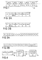
- Figure 1 is a diagram of a typical track layout of a tape.
- Figure 2A illustrates a data track where an error is detected before a block is written.
- Figure 2B illustrates a data track where an error is detected after a block has been written.
- Figures 3A and 3B illustrate track layouts where all blocks labeled "N" have an error detected.
- Figure 4 is a block diagram of a tape drive control unit for monitoring and storing tape position data.
- Figures 5, 5A, 5B and 5C illustrate the positioning of the tape to correct errors in data blocks of the tape.
- a method for removing or reducing read errors and write errors during data transfer operations due to debris on a tape or on a head of a tape drive.
- the method is applicable to 1/4-inch tape cartridges or any other system in which a recording media, such as a tape, is in contact with the head.
- the present invention will be described with respect to hard write errors since such errors are typically the most serious errors and the most difficult errors to correct.
- the method works equally well for read errors.
- the device In most tape drives, the device is operated in a "streaming" mode. That is, the tape is kept running continuously from one end to the other while fixed blocks of data bytes are written one track at a time.
- Figure 1 shows a typical track layout of a tape 10.
- Data blocks N, N+1, N+2, ... of the tape 10 are normally of equal size (typically containing 512 or 1024 bytes of user data).
- the gap area between data blocks is typically small and can be recorded with high density bit patterns.
- a tape drive may detect a "bad" block, i.e. a block containing debris on the tape 10 or on the head of the tape drive at a point on the tape 10, during the write operation (read-while-write mode) and will normally rewrite the block further down the tape 10.
- Figures 2A and 2B illustrate this process.
- block N+1 has been determined as a bad block.
- the drive determines that block N+1 is bad before it actually has finished writing that block, the N+1 block can be rewritten in the next block as shown.
- the distance between the write head and the read head is larger than the distance between adjacent data blocks.
- Figure 28 illustrates the situation where the distance between the write head and the read head is large, and the drive is physically writing block N+2 when block block N+1 has been determined as a bad block. When this occurs, block N+1 is not rewritten until block N + 2 has been written.
- the actual rewrite sequence therefore, may vary depending upon the actual format of the system and its requirements. However, any bad block will be rewritten at some point further down the tape track.
- Figure 3A illustrates a situation in which a hard write error occurs where block N has been recorded sixteen times and each block N is bad, i.e. each has failed the read-while-write check. The system will then stop the tape 10 and report a hard write error. Depending upon the system, other hard write error layouts may also occur like that shown in Figure 3B in which all data block N's of the tape 10 are bad. When this hard write error situation occurs like that shown in Figure 3B, a host system will be incapable of detecting whether any recorded block N's can be reliably read back at a later time. A further problem occurs when new data is appended to the recorded tape, for example, after a manual head cleaning operation. In addition, predicting how many of the N blocks were actually recorded on the tape cannot be determined.
- the drive cannot reliably read forward until the last block N because the drive cannot detect whether the block is the last one recorded. Since the drive is continuously unable to write block N correctly, a high probability exists that some debris has accumulated on the head. Debris must then be removed or at least reduced as hereinafter described.
- the drive When rewriting of a block is required, the drive keeps track of the number of blocks being rewritten.
- the drive monitors where it is physically located on the tape 10 at all times. This may be performed by measuring the distance from one of the ends of the tape by counting pulses from a tachometer mouiited on a motor system which moves the tape 10. Pulses may be generated and counted by motor brushes or counted from Hall effect sensors which can be used to control the operation of brushless motors or by similar means.
- tapes with prerecorded information along one or more of the tracks may also be used. Such specially recorded track information may then be used to determine the current location of the tape.
- the drive When a hard write error occurs, the drive ceases writing after a predetermined number of rewrites. This number is less than the number of allowable rewrites when using a format standard.
- the drive stores tape location data for the last block it tried to write regardless of whether it was able to detect this block. This location will be hereinafter referred to as point T.
- FIG 4 shows a block diagram of a tape drive control unit which monitors and stores such tape positions.
- the RAM 14 stores data generated by the control unit 12 and transfers the stored data back to the control unit 12.
- a motor system 16 transfers signals for driving of the tape by the control unit 12. These signals carry information which may be used by the control unit 12 to determine the physical tape position.
- the signals may be pulses which are related to the rotation of the motor generated by a tachometer or a similar device.
- the control unit 12 may then calculate the position of the tape based on the input from the motor system 16. This information is then stored in the storage device 14. If required, the control unit 12 may read this information at a later time during its operation.
- System operation begins by the drive running the tape in an opposite direction when an error is detected.
- the actual time may vary depending upon the particular tape and system being used, but in general, this distance should at least be equivalent to several hundred blocks of data.
- the tape continues to run in the same direction away from point T while slowly moving the head downward until the recording gaps are at or below the lower tape edge.
- the tape is then stopped and run in the opposite direction while gradually moving the head upwards until the recording gaps are at or above the upper edge of the tape.
- the tape continues running in the same direction while moving the head down until it is in a correct position for reading and recording on the track. If necessary, the tape continues running until the head is well back into an already recorded area of the tape.
- the tape is then stopped and moved in the opposite or original direction again until the head is in the area between the last good block N-1 and the point T. In this area, the write operation is started while the tape is still running in the same direction.
- the drive starts writing block N and performs a read-while-write operation at the same time. Block N continues to be written in a read-while-write mode until it is determined as good or until the maximum number of allowable block rewrites has been reached.
- the head movement operation may, as well, be performed in the opposite mode, that is, moving the head upwards and then moving it downwards. It is not critical to move the head such that the gaps are actually crossing over the edges of the tape; however, the head movement should at least cover a reasonable distance across the tape.
- This method of moving the head up or down while moving the tape forward and in reverse may be performed repeatedly.
- Figures 5A - 5C illustrate this process.
- Figure 5A shows the write operation taking place until a fixed number of bad blocks (N) have been recorded. At this point, information may be stored regarding the location of the last recorded block N (point T).
- the tape 10 is then moved in the opposite direction for a specified distance, typically several hundred blocks as shown in Figure 5B.
- the tape 10 is then moved forward as shown in Figure 5C while reading until the last good block N-1 is detected.
- the write operation is restarted by writing either blocks N or N-1 or gap information until the point T is reached.
- the writing of block N is continued while performing the read-while-write operation until block N is determined to be good or the maximum number of rewritten blocks is reached.
- the operation of moving the tape 10 in the opposite direction first and then back again effectively removes debris on the head by wearing it down. In some cases, the operation may be repeated and, if necessary, the tape 10 may move a greater distance in the opposite direction. If, however, debris remains on the head, the system may implement the following steps to avoid system hang-ups, "down" time, and the like.
- the read-while-write checking is performed with a read threshold set at a lower level, for example, five or ten percent. If debris still exists on the head, lowering of the threshold increases the probability of the block being read as good since a lower threshold decreases the quality requirement.
- the drive terminates the write operation with this block and reports to the control unit 12 that the last block was determined as good by using the lower threshold level.
- This lowering of the read-while-write threshold does not typically remove any debris on the head, but enables the drive to terminate the write operation with a good block which is important for avoiding system hang-ups.
Landscapes
- Engineering & Computer Science (AREA)
- Signal Processing (AREA)
- Digital Magnetic Recording (AREA)
Claims (7)
- Procédé de détection et de correction d'une erreur durant une opération de transfert de données concernant un courant de données d'une bande, dans un système d'entraínement de bande comprenant une tête d'écriture/lecture, ledit procédé comprenant :caractérisé parla surveillance de l'emplacement de ladite bande durant ladite opération de transfert de données, ledit emplacement étant surveillé par rapport à une extrémité de ladite bande ou de données préenregistrées sur ladite bande, dont les emplacements sont connus par la fabrication de ladite bande, dans lequel ladite surveillance est effectuée en continu;la détection de l'occurrence de ladite erreur sur ladite bande;l'arrêt de ladite opération de transfert de données lors de ladite occurrence de ladite erreur;le rembobinage de ladite bande jusqu'à un emplacement sensiblement éloigné de l'emplacement de ladite erreur;l'avancée de la bande jusqu'à un emplacement d'un dernier bloc de bonnes données précédant l'emplacement de ladite erreur;le déplacement de la tête dans une direction d'une bordure de bande durant ledit rembobinage de la bande;le déplacement de ladite tête dans une direction d'éloignement de ladite bordure de bande durant ladite avancée de la bande;l'élimination de débris depuis ladite bande et/ou de ladite tête d'écriture/lecture par ledit rembobinage et/ou l'avancée de la bande et/ou le déplacement de la tête;la réécriture/relecture d'un bloc de données dudit courant de données audit emplacement de l'erreur; etl'achèvement de ladite opération de transfert de données, si un signal de lecture dépasse un niveau de seuil indicatif de l'absence d'erreur sur ladite bande.
- Procédé selon la revendication 1, comprenant en outre l'étape de :diminution dudit niveau de seuil, si ladite erreur a de nouveau lieu après un nombre prédéterminé de répétitions de ladite étape de réécriture/relecture.
- Procédé selon la revendication 1 ou 2, comprenant en outre l'étape de continuation de ladite opération de transfert de données après une réécriture/relecture dudit bloc de données.
- Procédé selon l'une des revendications précédentes, dans lequel ladite étape de réécriture écrit une information de code de discontinuité, au lieu dudit bloc de données, audit emplacement de ladite erreur.
- Procédé selon la revendication 4, comprenant en outre l'étape de continuation de ladite opération de transfert de données après l'écriture de ladite information de code de discontinuité.
- Système de détection et de correction d'erreurs durant une opération de transfert de données concernant un courant de données d'une bande dans un système d'entraínement de bande, ledit système comprenant :caractérisé parun moyen servant à surveiller l'emplacement de la bande durant ladite opération de transfert de données, ledit emplacement étant surveillé par rapport à une extrémité de ladite bande ou des données préenregistrées sur la bande, dont les emplacements sont connus par la fabrication de ladite bande, dans lequel ladite surveillance est effectuée en continu;un moyen servant à détecter l'occurrence de ladite erreur sur la bande durant ladite opération de transfert de données;un moyen d'arrêt de ladite opération de transfert de données lors de ladite occurrence de l'erreur;un moyen de rembobinage de la bande vers un emplacement sensiblement éloigné de l'emplacement de ladite erreur;un moyen d'avancée de la bande vers un emplacement d'un dernier bloc de bonnes données précédant ledit emplacement de ladite erreur;un moyen de déplacement de la tête dans une direction d'une bordure de la bande;un moyen de déplacement de la tête dans une direction d'éloignement de ladite bordure de bande;ledit moyen exécutant ledit rembobinage et/ou avancée et/ou déplacement de manière que les débris puissent être éliminés de la bande et/ou de la tête d'écriture/lecture;un moyen de réécriture/relecture d'un bloc de données du courant de données audit emplacement de ladite erreur;un moyen de seuil servant à établir un niveau de seuil pour un signal de lecture, indicatif de l'absence d'erreur durant ladite opération de transfert de données.
- Système selon la revendication 6, comprenant en outre un moyen de réglage dudit niveau de seuil, si ledit moyen de réécriture/relecture ne parvient pas à corriger ladite erreur.
Applications Claiming Priority (2)
| Application Number | Priority Date | Filing Date | Title |
|---|---|---|---|
| US890006 | 1978-03-27 | ||
| US07/890,006 US5347407A (en) | 1992-05-29 | 1992-05-29 | Method and system for removing particles without requiring a separate cleaning mechanism from a tape in a tape drive system |
Publications (3)
| Publication Number | Publication Date |
|---|---|
| EP0572711A2 EP0572711A2 (fr) | 1993-12-08 |
| EP0572711A3 EP0572711A3 (fr) | 1995-01-11 |
| EP0572711B1 true EP0572711B1 (fr) | 1998-11-25 |
Family
ID=25396104
Family Applications (1)
| Application Number | Title | Priority Date | Filing Date |
|---|---|---|---|
| EP92116280A Expired - Lifetime EP0572711B1 (fr) | 1992-05-29 | 1992-09-23 | Méthode et système pour détecter et corriger des erreurs sur une bande dans un système d'entrainement de bande |
Country Status (4)
| Country | Link |
|---|---|
| US (1) | US5347407A (fr) |
| EP (1) | EP0572711B1 (fr) |
| JP (1) | JPH0652508A (fr) |
| DE (1) | DE69227677T2 (fr) |
Families Citing this family (8)
| Publication number | Priority date | Publication date | Assignee | Title |
|---|---|---|---|---|
| DE69316505T2 (de) * | 1992-10-08 | 1998-07-16 | Koninkl Philips Electronics Nv | Bandreinigungssystem mit Magnetbandkassette und Magnetbandgerät |
| US6057973A (en) * | 1997-10-15 | 2000-05-02 | Bar; Refael | Method of seeking to tape segment without the use of inter-segment gap |
| JP3090130B2 (ja) * | 1998-11-18 | 2000-09-18 | 日本電気株式会社 | 磁気テープ装置 |
| US6577562B2 (en) * | 2001-04-02 | 2003-06-10 | International Business Machines Corporation | Method to allocate storage elements while in a reset state |
| US7064913B2 (en) * | 2002-01-09 | 2006-06-20 | Quantum Corporation | Enhanced read margining using dither enhanced write marginalization for mass data storage applications |
| US7372651B2 (en) * | 2003-03-07 | 2008-05-13 | Quantum Corporation | Introducing a noise signal into a read-back signal when data is written to a removable data storage medium |
| GB2422478A (en) * | 2005-01-21 | 2006-07-26 | Hewlett Packard Development Co | Tape data format having skip frames in areas of write failures |
| US7484040B2 (en) * | 2005-05-10 | 2009-01-27 | International Business Machines Corporation | Highly available removable media storage network environment |
Family Cites Families (12)
| Publication number | Priority date | Publication date | Assignee | Title |
|---|---|---|---|---|
| US3579211A (en) * | 1968-10-11 | 1971-05-18 | Datel Corp | Read-after-write verification of data on magnetic storage medium |
| US3731289A (en) * | 1972-02-11 | 1973-05-01 | Ibm | Cleaning apparatus and method in a magnetic tape unit |
| US4185306A (en) * | 1978-04-03 | 1980-01-22 | Dudley Don J | Magnetic tape processor having cleaning and evaluating means |
| JPS5740770A (en) * | 1980-08-26 | 1982-03-06 | Fujitsu Ltd | Magnetic tape control system |
| WO1982002611A1 (fr) * | 1981-01-21 | 1982-08-05 | Vyacheslav Vasilevich Golushko | Procede et installation d'enregistrement et de commande d'informations codees sur une bande magnetique |
| US4637023A (en) * | 1983-02-14 | 1987-01-13 | Prime Computer, Inc. | Digital data error correction method and apparatus |
| JPS60173775A (ja) * | 1984-01-28 | 1985-09-07 | Nippon Telegr & Teleph Corp <Ntt> | 磁気テ−プ記憶装置 |
| JPS6214305A (ja) * | 1985-07-12 | 1987-01-22 | Fujitsu Ltd | 磁気テ−プ装置のライトエラ−処理方法 |
| JPS63136303A (ja) * | 1986-11-28 | 1988-06-08 | Nec Corp | ポジシヨニング制御方式 |
| JPH01232576A (ja) * | 1988-03-12 | 1989-09-18 | Sharp Corp | 情報記録方法 |
| US5193033A (en) * | 1988-05-17 | 1993-03-09 | Mitsubishi Denki Kabushiki Kaisha | Magnetic recording and reproducing apparatus incorporating clogging detection |
| JPH04102274A (ja) * | 1990-08-20 | 1992-04-03 | Hitachi Ltd | 磁気記憶装置の制御方式 |
-
1992
- 1992-05-29 US US07/890,006 patent/US5347407A/en not_active Expired - Fee Related
- 1992-09-23 DE DE69227677T patent/DE69227677T2/de not_active Expired - Fee Related
- 1992-09-23 EP EP92116280A patent/EP0572711B1/fr not_active Expired - Lifetime
-
1993
- 1993-05-31 JP JP5128809A patent/JPH0652508A/ja active Pending
Also Published As
| Publication number | Publication date |
|---|---|
| EP0572711A2 (fr) | 1993-12-08 |
| DE69227677T2 (de) | 1999-04-22 |
| JPH0652508A (ja) | 1994-02-25 |
| EP0572711A3 (fr) | 1995-01-11 |
| DE69227677D1 (de) | 1999-01-07 |
| US5347407A (en) | 1994-09-13 |
Similar Documents
| Publication | Publication Date | Title |
|---|---|---|
| US5381292A (en) | Method for self-cleaning dat drive tape heads | |
| US7177979B2 (en) | Method for preventing data loss due to repeated writes to a given track on a magnetic disk drive | |
| EP0929067B1 (fr) | Appareil de disque magnétique | |
| JP5022240B2 (ja) | テープ媒体へのデータの上書き方法、及びその方法を具備した磁気テープ装置 | |
| US7280293B2 (en) | Multi-level mapping of tape error recoveries | |
| JPH0745010A (ja) | テープ・ストレージ装置のエラー回復方法及び装置 | |
| US6366422B1 (en) | Helical scan tape drive error recovery using track profile mapping | |
| US20080007856A1 (en) | Magnetic tape storage, method for writing data to magnetic tape, and medium for writing data program | |
| US9471255B2 (en) | Tape storage device and writing method therefor | |
| US5347407A (en) | Method and system for removing particles without requiring a separate cleaning mechanism from a tape in a tape drive system | |
| EP0892392A2 (fr) | Bande de nettoyage et amorce intégrée | |
| US4783784A (en) | Magnetic tape system with write retry means | |
| JPH08501168A (ja) | 単一の記録終端及び記録始端フォーマット指示器を有するデータ記録システム | |
| JP2755370B2 (ja) | 周辺記憶システム及びデータ処理システムの制御方法 | |
| EP1755123A2 (fr) | Procédé et dispositif d'un format à bande magnétique avec une très haute tolérance d'erreur | |
| US7167332B2 (en) | Method and apparatus for recording data onto a recording medium including warning of the approach to an end of medium position | |
| US6038092A (en) | System for reading data from a distorted magnetic tape media | |
| US20060209446A1 (en) | Method for erasing data from magnetic tape storage media | |
| JPH04358360A (ja) | 磁気記録再生装置のリカバリ方式 | |
| JP3598910B2 (ja) | 情報記録/再生装置 | |
| GB2422478A (en) | Tape data format having skip frames in areas of write failures | |
| JP3704943B2 (ja) | 記録再生装置及びテープカセット | |
| JPH01162276A (ja) | 磁気テープ装置におけるデータエラー処理方法 | |
| GB2419223A (en) | Cleaning read/write heads of a magnetic tape recording system | |
| JPH05151685A (ja) | デイスク装置 |
Legal Events
| Date | Code | Title | Description |
|---|---|---|---|
| PUAI | Public reference made under article 153(3) epc to a published international application that has entered the european phase |
Free format text: ORIGINAL CODE: 0009012 |
|
| AK | Designated contracting states |
Kind code of ref document: A2 Designated state(s): DE FR GB |
|
| PUAL | Search report despatched |
Free format text: ORIGINAL CODE: 0009013 |
|
| AK | Designated contracting states |
Kind code of ref document: A3 Designated state(s): DE FR GB |
|
| 17P | Request for examination filed |
Effective date: 19950511 |
|
| 17Q | First examination report despatched |
Effective date: 19960902 |
|
| GRAG | Despatch of communication of intention to grant |
Free format text: ORIGINAL CODE: EPIDOS AGRA |
|
| GRAG | Despatch of communication of intention to grant |
Free format text: ORIGINAL CODE: EPIDOS AGRA |
|
| GRAH | Despatch of communication of intention to grant a patent |
Free format text: ORIGINAL CODE: EPIDOS IGRA |
|
| RAP1 | Party data changed (applicant data changed or rights of an application transferred) |
Owner name: TANDBERG DATA ASA |
|
| GRAH | Despatch of communication of intention to grant a patent |
Free format text: ORIGINAL CODE: EPIDOS IGRA |
|
| GRAA | (expected) grant |
Free format text: ORIGINAL CODE: 0009210 |
|
| AK | Designated contracting states |
Kind code of ref document: B1 Designated state(s): DE FR GB |
|
| PG25 | Lapsed in a contracting state [announced via postgrant information from national office to epo] |
Ref country code: FR Free format text: LAPSE BECAUSE OF FAILURE TO SUBMIT A TRANSLATION OF THE DESCRIPTION OR TO PAY THE FEE WITHIN THE PRESCRIBED TIME-LIMIT Effective date: 19981125 |
|
| REF | Corresponds to: |
Ref document number: 69227677 Country of ref document: DE Date of ref document: 19990107 |
|
| EN | Fr: translation not filed | ||
| PG25 | Lapsed in a contracting state [announced via postgrant information from national office to epo] |
Ref country code: GB Free format text: LAPSE BECAUSE OF NON-PAYMENT OF DUE FEES Effective date: 19990923 |
|
| PLBE | No opposition filed within time limit |
Free format text: ORIGINAL CODE: 0009261 |
|
| 26N | No opposition filed | ||
| GBPC | Gb: european patent ceased through non-payment of renewal fee |
Effective date: 19990923 |
|
| PGFP | Annual fee paid to national office [announced via postgrant information from national office to epo] |
Ref country code: DE Payment date: 20030930 Year of fee payment: 12 |
|
| PG25 | Lapsed in a contracting state [announced via postgrant information from national office to epo] |
Ref country code: DE Free format text: LAPSE BECAUSE OF NON-PAYMENT OF DUE FEES Effective date: 20050401 |