EP0572831A2 - Méthode pour surveiller la participation et réduire les erreurs de bit pour communications commutées dans un système numérique - Google Patents
Méthode pour surveiller la participation et réduire les erreurs de bit pour communications commutées dans un système numérique Download PDFInfo
- Publication number
- EP0572831A2 EP0572831A2 EP93107727A EP93107727A EP0572831A2 EP 0572831 A2 EP0572831 A2 EP 0572831A2 EP 93107727 A EP93107727 A EP 93107727A EP 93107727 A EP93107727 A EP 93107727A EP 0572831 A2 EP0572831 A2 EP 0572831A2
- Authority
- EP
- European Patent Office
- Prior art keywords
- information
- diu
- switching
- interface elements
- output
- Prior art date
- Legal status (The legal status is an assumption and is not a legal conclusion. Google has not performed a legal analysis and makes no representation as to the accuracy of the status listed.)
- Granted
Links
Images

Classifications
-
- H—ELECTRICITY
- H04—ELECTRIC COMMUNICATION TECHNIQUE
- H04L—TRANSMISSION OF DIGITAL INFORMATION, e.g. TELEGRAPHIC COMMUNICATION
- H04L49/00—Packet switching elements
- H04L49/15—Interconnection of switching modules
- H04L49/1515—Non-blocking multistage, e.g. Clos
- H04L49/153—ATM switching fabrics having parallel switch planes
-
- H—ELECTRICITY
- H04—ELECTRIC COMMUNICATION TECHNIQUE
- H04L—TRANSMISSION OF DIGITAL INFORMATION, e.g. TELEGRAPHIC COMMUNICATION
- H04L49/00—Packet switching elements
- H04L49/55—Prevention, detection or correction of errors
-
- H—ELECTRICITY
- H04—ELECTRIC COMMUNICATION TECHNIQUE
- H04L—TRANSMISSION OF DIGITAL INFORMATION, e.g. TELEGRAPHIC COMMUNICATION
- H04L12/00—Data switching networks
- H04L12/54—Store-and-forward switching systems
- H04L12/56—Packet switching systems
- H04L12/5601—Transfer mode dependent, e.g. ATM
- H04L2012/5625—Operations, administration and maintenance [OAM]
- H04L2012/5627—Fault tolerance and recovery
-
- H—ELECTRICITY
- H04—ELECTRIC COMMUNICATION TECHNIQUE
- H04L—TRANSMISSION OF DIGITAL INFORMATION, e.g. TELEGRAPHIC COMMUNICATION
- H04L49/00—Packet switching elements
- H04L49/15—Interconnection of switching modules
- H04L49/1515—Non-blocking multistage, e.g. Clos
- H04L49/1523—Parallel switch fabric planes
Definitions
- the data transmission on lines and cables is disruptive influences, e.g. exposed to electromagnetic fields that change the information to be transmitted, e.g. B. one or more bits are 'flipped' during transmission. Since international long-distance connections in particular are susceptible to bit errors, international standardization bodies - such as CCITT - set minimum requirements for bit error rates. Optical transmission links are subject to external influences considerably less, so that the transmission security when using optical transmission links is very high.
- the switching networks are usually implemented twice or even several times. This makes it possible to switch through the information on another switching matrix level in the event of a switching matrix level malfunctioning. On the one hand, this can be done in such a way that one switching matrix level is in the idle state, while the other switching matrix level actively switches through the information; on the other hand, both switching network levels can actively switch through the relevant information.
- the switching path in the switching matrix must be defined and set beforehand. This means that the information to be switched through arriving at the switching matrix enters the switching matrix via an input which is generally already fixed before the switching process or is only yet to be determined and exits again via an output which is also to be determined.
- the definition of which input / output is used when switching through an information stream consisting of several information words is made by evaluating the signaling information through the central control platform of the communication system, which determines and sets the switching path through the switching matrix.
- a central control platform is generally understood to mean the interaction of the central and decentralized control units of a communication system.
- the central control platform has saved the current data on the current occupancy of the inputs / outputs of the entire switching matrix and the routes used. This enables the central control platform Assign inputs / outputs that are not yet assigned at any time as well as the switching paths assigned to them through the switching matrix to further information streams that are still to be switched. A possible termination or termination of an existing connection is also carried out by the central control platform, which leads to the release of occupied inputs / outputs as well as the switching paths used.
- the associated data must therefore be constantly maintained by the central control platform, ie updated as required. Since this is dynamically changing data, maintenance takes place in the memory of the central control platform; a storage on an external storage medium, such as. B. a hard drive, is not possible because of the long access time involved.
- sporadic and permanent errors can occur (bit error rate). They mostly express themselves in the fact that one or more bits are falsified during the switching process, an inadmissible bit error rate arises or even an incorrect information stream is output. This can result in temporary or permanent incorrect output; sporadic errors have their origin in electromagnetic coupling, in thermal influences or aging components, while permanently occurring errors from defective or falsified hold memory areas, defective voice memories, defective addressing logic for hold and voice memories, from defective or outdated components (such as lasers) or a defective power supply result.
- Error detection methods for detecting and correcting bit errors in switching matrixes have so far been used e.g. implemented in the form of tracking monitoring. Such a method is known from German Offenlegungsschrift 24 27 668.
- additional test information is added to the information words defining the information per channel.
- the check information can be a parity bit, for example. This is the binary checksum over the individual bits of the corresponding information word.
- a binary checksum of the switched information word is again determined and its parity compared with the transmitted parity bit. If both differ from each other, there is a transmission error that is recorded in a corresponding table memory. In this way, statements can be made about the state of the corresponding switching matrix level over certain periods of time. With these statistical statements, the switching matrix level that has had the lowest bit error rate in the past can be used to switch through the information streams.
- German patent application P 41 28 412.7 It is used to determine test information for the information words forming the information in peripheral units before the switching process. This is appended to the relevant information word. This is followed by a duplication of the information word supplemented by the test information and a subsequent connection through both switching network levels. After the switching process, the information words supplemented with the test information are subjected to a new test information determination and the result compared with the test information also transmitted. In parallel, the information words themselves are compared bit by bit. Conclusions can then be drawn from both evaluations as to whether there is a transmission error or not, or statements can be made (albeit limited) about which bit has been falsified, and corrections can be made in this case.
- Errors that cause incorrect switching in the switching matrix also have a serious effect, i.e. an information stream entering a certain input of the switching matrix does not leave the switching matrix at the intended output, but due to a sporadic or permanent error during the setting process via an incorrect output is forwarded to any end user. Such errors cannot be discovered centrally; often it is only the end user who determines the faulty connection.
- the object of the invention is to keep the effect of errors as low as possible, in particular with regard to faulty switching through to end users in the coupling fields of digital communication systems.
- Claim 2 relates to a first embodiment of the test evaluation information.
- This is a check bit obtained from a binary checksum.
- the binary checksum is formed from the information word and the attached source number bit.
- other test assessment procedures are also conceivable; for example, the binary checksum can only be formed with every second bit.
- the test evaluation can be made using mathematical functions such as multiplication or division.
- the source number is encrypted in 1-bit information. In order to record the complete source number, these bits must therefore be stored and filled in until the source number is complete.
- the source number is a characteristic number for the place where the information flow has entered the communication system. This entry point is formed by interface elements on the input side.
- the switching process itself is characterized in that a selected output, which is formed by output-side interface elements, is assigned to the respective input location. Since the source number is switched through together with the information stream, it can be determined at the output-side interface elements whether the switching through the switching matrix was correct with regard to the input / output assignment.
- Claim 4 relates to a first embodiment of the invention. It is provided that the source number is stored in the output-side interface elements via a communication channel between the central control platform and the interface element when the connection is established. If the information streams supplied by both switching network levels are different and contain different source numbers, the output-side interface elements can independently select and output the correctly switched information stream.
- a second embodiment of the invention is defined in claim 5. It is provided that in the event of a permanent inequality of the information flows delivered by the respective switching matrix levels and a mismatch of the associated source numbers, a message is transmitted from the output-side interface elements to the central control platform.
- a third embodiment of the invention is defined in claim 6.
- a transmission procedure cyclically transmits the source numbers stored in the central control platform to the respective interface elements on the output side. In the event of a permanent discrepancy in the through-going information streams, they can decide for themselves which of the information streams were transmitted correctly. Such an approach combines 'dynamic' points of view with a quick response in the event of an error.
- the application of the invention to asynchronously set switching matrixes is defined. It must be noted that the method according to the invention is only used after a sufficiently long protection time, since it is only after this time that it is ensured that both switching matrix levels are switched through. Furthermore, the method according to the invention can be applied to individual switching matrix components of a switching matrix. Such a configuration ensures that the information streams and bit errors to be passed on are already cleaned up within the switching matrix.
- An advantage of the invention is in particular that after a total failure of the central control platform, the connection data stored there can be regenerated directly from the source numbers available in the output-side interface elements, which considerably simplifies the maintenance of existing connections.
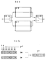
- the switching network SN is designed twice and is divided into two switching network levels SN0, SN1.
- the input-side or output-side interface elements DIU (A), DIU (B) act as an interface between the communication network and the communication system KS.
- an information stream penetrating into the communication system KS and consisting of a multiplicity of information words I (o) ... I (N ) is transmitted before switching through through the switching network SN with one for the respective information word I (x ) provide characteristic additional information ZU.
- a source number Q is generally permanently assigned to the input of the input-side interface elements DIU (A) at which the information words have penetrated. Furthermore, by evaluating the signaling information, a target number Z corresponding to the source number Q, ie the output from which the information words leave the interface elements DIU (B) on the output side after the switching process, is determined.
- the source number Q and the target number Z are stored in a table in the central control platform CP. With the aid of a suitable algorithm, the central control platform CP determines the switching path in the switching network SN from both variables and sets it. The central control platform CP thus determines which path through the switching network SN the information stream I (0) ... I (N) to be switched must use.
- an information word I (x) consists of 8 bits.
- the incoming information words I (o) ... I (N) are first provided with the source ID number Q, which is permanently assigned to the respective input of the input-side interface elements DIU (A), and then as the ninth bit the information word I (x) is added bit by bit across several information words. Subsequently, a parity is formed via the information word I (x) and the respective source number bit Q, the result of which is recorded as a parity bit P in bit 10.
- Each information word I (x) is thus loaded with additional information ZU consisting of the parity bit P and the source number bit Q before the switching process.
- each information word I (x) with its additional information ZU being routed via the respective switching network level SN0, SN1, taking into account the switching path determined by the central control platform CP becomes.
- the information words I (x) are subjected to a new evaluation together with their additional information ZU which is also transmitted.
- a first evaluation there is a new parity check of both switched through information words I (x) supplemented by the source number bit Q. The result of that parity check is compared with the transmitted parity bit P. Both are switched through in a second evaluation
- Information words I (x) together with the co-transmitted source number bit Q are compared bit by bit.
- the information word I (x) of the two switching matrix levels SN0, SN1 do not match, the information word I (x) is forwarded to the end user, which, including the source number bit Q, is consistent with regard to its transmitted parity information P. If this condition is not met, the information word I (x) is forwarded to the end user, which was routed via the switching matrix level with the better statistical quality data. These are recorded in a statistical function f (s).
- 2b shows the method according to the invention in the event of a discrepancy in the source numbers Q.
- the output-side interface elements DIU (B) are informed of the source numbers Q assigned to the respective outputs using a communication channel between the central control platform and the output-side interface elements DIU (B).
- the source numbers Q are thus currently stored in the output interface elements DIU (B).
- the output-side interface element DIU (B) can independently determine and output the correctly connected information flow. Fault data can be stored peripherally or reported to the central control platform CP.
- the output-side interface elements DIU (B) send I (0) ... I (N) , J (l) ... J (k) if the information streams delivered via both switching network levels SN0, SN1 differ. a message to the central control platform CP.
- This contains the destination number and the source numbers Q of the information streams I (0) ... I (N) , J (l) ... J (k) connected through both switching network levels SN0, SN1 .
- the central control platform CP determines the associated destination numbers for both source numbers Q with the aid of their internally stored connection data. This can be used to determine in a simple manner which of the two switched information streams has been correctly transmitted. The result of this evaluation is communicated by the central control platform CP to the output-side interface elements DIU (B) via a corresponding message for the selection of the correct information flow.
- the source numbers Q stored in the central control platform CP are transmitted cyclically to the associated output-side interface units DIU (B) by a transmission procedure U and stored there.
- the output-side interface units DIU (B) there is an image of the source numbers Q maintained in the central control platform CP.
- the output-side interface elements DIU (B) can, with a high degree of probability, immediately decide independently which of the two switching network levels SN0, SN1 is delivered Information flow to the end participant is to be forwarded.
- the connection data stored therein are lost.
- the source numbers Q present in the output-side interface units DIU (B) are available for updating the connection data of the central control platform CP. In practice, this means that the central control platform CP can be put back into operation very quickly without interrupting existing connections.
- the method according to the invention can also be used on asynchronously set switching network levels. They are characterized in that the switching of information streams over the respective switching matrix levels is different At times, there are brief information streams from various sources in the output interface elements DIU (B). It should therefore be noted that a sufficiently long protection time must be set up, in which the diversity of the information streams routed over both switching network levels SN0, SN1 does not cause an error reaction in the output-side interface elements DIU (B). The method according to the invention can only be carried out after this protective time has expired.
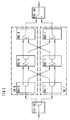
- FIG. 3 shows the switching network SN known from FIG. 1 with the switching network levels SN SN, SN1 and the input-side and output-side interface elements DIU (A), DIU (B).
- a switching network level SN0, SN1 consists of several - in the present embodiment three - switching network components.
- the individual switching matrix components are crossed out among themselves. This means that in the event of a fault, the switch units S shown in the respective switching matrix components can be switched over to the respective other switching matrix component.
Landscapes
- Engineering & Computer Science (AREA)
- Computer Networks & Wireless Communication (AREA)
- Signal Processing (AREA)
- Detection And Prevention Of Errors In Transmission (AREA)
- Data Exchanges In Wide-Area Networks (AREA)
- Communication Control (AREA)
Applications Claiming Priority (2)
| Application Number | Priority Date | Filing Date | Title |
|---|---|---|---|
| DE4218054 | 1992-06-01 | ||
| DE4218054A DE4218054C1 (de) | 1992-06-01 | 1992-06-01 | Verfahren zur Mitlaufüberwachung und Bitfehlerreduktion für durchgeschaltete Verbindungen in digitalen Kommunikationssystemen |
Publications (3)
| Publication Number | Publication Date |
|---|---|
| EP0572831A2 true EP0572831A2 (fr) | 1993-12-08 |
| EP0572831A3 EP0572831A3 (fr) | 1994-03-09 |
| EP0572831B1 EP0572831B1 (fr) | 1998-11-25 |
Family
ID=6460157
Family Applications (1)
| Application Number | Title | Priority Date | Filing Date |
|---|---|---|---|
| EP93107727A Expired - Lifetime EP0572831B1 (fr) | 1992-06-01 | 1993-05-12 | Méthode pour surveiller la participation et réduire les erreurs de bit pour communications commutées dans un système numérique |
Country Status (6)
| Country | Link |
|---|---|
| US (1) | US5442647A (fr) |
| EP (1) | EP0572831B1 (fr) |
| AT (1) | ATE173869T1 (fr) |
| DE (2) | DE4218054C1 (fr) |
| DK (1) | DK0572831T3 (fr) |
| ES (1) | ES2125283T3 (fr) |
Cited By (1)
| Publication number | Priority date | Publication date | Assignee | Title |
|---|---|---|---|---|
| WO1999003300A3 (fr) * | 1997-07-11 | 1999-04-01 | Ericsson Telefon Ab L M | Terminaison redondante |
Families Citing this family (7)
| Publication number | Priority date | Publication date | Assignee | Title |
|---|---|---|---|---|
| EP0665701A1 (fr) * | 1994-01-26 | 1995-08-02 | Siemens Aktiengesellschaft | Procédé pour la surveillance des chemins de connexion dans un central de commutation numérique à division dans le temps |
| EP0732828B1 (fr) * | 1995-03-16 | 2008-02-27 | Nokia Siemens Networks Gmbh & Co. Kg | Réseau de communication optimisé en redondance pour la transmission de signaux de données |
| DE59711604D1 (de) * | 1996-01-19 | 2004-06-17 | Siemens Schweiz Ag Zuerich | Verfahren zur Datenübertragung zwischen zwei Stationen |
| US6831927B1 (en) * | 1999-05-13 | 2004-12-14 | Lucent Technologies Inc. | Fault protection for hitless and errorless switching of telecommunications signals |
| EP1280373B1 (fr) | 2001-07-23 | 2004-11-03 | Alcatel | Elément de réseau pour des signaux du réseau de transport optique |
| DE102004062010A1 (de) * | 2004-04-08 | 2005-10-27 | Robert Bosch Gmbh | Verfahren und Vorrichtung zur Codeerzeugung bei der Übertragung von Daten über ein Kommunikationssystem |
| DE102005012069A1 (de) * | 2005-03-16 | 2006-09-21 | Robert Bosch Gmbh | Verfahren zur Fehlerbehandlung |
Family Cites Families (9)
| Publication number | Priority date | Publication date | Assignee | Title |
|---|---|---|---|---|
| FR2233780B1 (fr) * | 1973-06-13 | 1977-05-06 | Materiel Telephonique | |
| US4345324A (en) * | 1980-07-09 | 1982-08-17 | Christian Rovsing A/S | Process and system for error detection in a computer-controlled telephone exchange |
| GB2120041B (en) * | 1982-04-24 | 1985-10-02 | Plessey Co Plc | Digital switching network for telecommunications exchange |
| US4490817A (en) * | 1982-12-13 | 1984-12-25 | At&T Bell Laboratories | Packet error rate measurements by distributed controllers |
| AR241357A1 (es) * | 1986-06-27 | 1992-05-29 | Siemens Ag | Disposicion de circuito para vigilar la transmision de informacion en vias de enlace tetrafilares conmutadas. |
| DE3821871A1 (de) * | 1988-06-29 | 1990-01-18 | Philips Patentverwaltung | Breitbandkoppeleinrichtung |
| EP0384936B1 (fr) * | 1989-03-03 | 1994-06-15 | Siemens Aktiengesellschaft | Procédé et dispositif pour transmettre des paquets d'information provenant de lignes d'entrée via un dispositif à communication de paquets |
| US5249292A (en) * | 1989-03-31 | 1993-09-28 | Chiappa J Noel | Data packet switch using a primary processing unit to designate one of a plurality of data stream control circuits to selectively handle the header processing of incoming packets in one data packet stream |
| DE4128412C1 (fr) * | 1991-08-27 | 1992-12-10 | Siemens Ag, 8000 Muenchen, De |
-
1992
- 1992-06-01 DE DE4218054A patent/DE4218054C1/de not_active Expired - Fee Related
-
1993
- 1993-05-12 EP EP93107727A patent/EP0572831B1/fr not_active Expired - Lifetime
- 1993-05-12 DK DK93107727T patent/DK0572831T3/da active
- 1993-05-12 ES ES93107727T patent/ES2125283T3/es not_active Expired - Lifetime
- 1993-05-12 AT AT93107727T patent/ATE173869T1/de not_active IP Right Cessation
- 1993-05-12 DE DE59309148T patent/DE59309148D1/de not_active Expired - Fee Related
- 1993-05-24 US US08/064,897 patent/US5442647A/en not_active Expired - Fee Related
Cited By (4)
| Publication number | Priority date | Publication date | Assignee | Title |
|---|---|---|---|---|
| WO1999003300A3 (fr) * | 1997-07-11 | 1999-04-01 | Ericsson Telefon Ab L M | Terminaison redondante |
| GB2342249A (en) * | 1997-07-11 | 2000-04-05 | Ericsson Telefon Ab L M | Redundancy termination |
| US6337860B1 (en) | 1997-07-11 | 2002-01-08 | Telfonaktiebolaget Lm Ericsson | Redundancy termination |
| GB2342249B (en) * | 1997-07-11 | 2002-10-02 | Ericsson Telefon Ab L M | Redundancy termination |
Also Published As
| Publication number | Publication date |
|---|---|
| ATE173869T1 (de) | 1998-12-15 |
| DK0572831T3 (da) | 1999-08-09 |
| ES2125283T3 (es) | 1999-03-01 |
| DE59309148D1 (de) | 1999-01-07 |
| US5442647A (en) | 1995-08-15 |
| EP0572831A3 (fr) | 1994-03-09 |
| EP0572831B1 (fr) | 1998-11-25 |
| DE4218054C1 (de) | 1993-11-11 |
Similar Documents
| Publication | Publication Date | Title |
|---|---|---|
| EP0384936B1 (fr) | Procédé et dispositif pour transmettre des paquets d'information provenant de lignes d'entrée via un dispositif à communication de paquets | |
| EP0645918A2 (fr) | Procédé et dispositif de circuit pour la transmission de cellules de messages par les paires de voies redondantes virtuelles d'un réseau de communication ATM | |
| EP0453607B1 (fr) | Méthode et dispositif pour réduire la perte de paquets d'information, transmis par un commutateur de paquets | |
| EP0645919A2 (fr) | Procédé pour la transmission de cellules de messages par les paires de voies redondantes virtuelles d'un réseau de communication ATM | |
| DE4128412C1 (fr) | ||
| EP0381011A2 (fr) | Réseau de transmission avec des noeuds commutables | |
| EP0219917B1 (fr) | Dispositif de commutation avec correction de fautes | |
| DE3614062A1 (de) | Verfahren zur flusssteuerung von daten innerhalb eines vermaschten datennetzes | |
| DE4218054C1 (de) | Verfahren zur Mitlaufüberwachung und Bitfehlerreduktion für durchgeschaltete Verbindungen in digitalen Kommunikationssystemen | |
| DE4308174C1 (de) | Verfahren für Punkt-zu-Mehrpunkt-Verbindungen in selbstroutenden ATM-Koppelfeldern | |
| EP0448734A1 (fr) | Disposition de circuit pour tester par routine l'interface entre les groupes de transmission et le réseau de commutation d'un central de télécommunication à MIC | |
| DE69015165T2 (de) | Einrichtung zur Bewertung der Übertragungsqualität. | |
| AT404656B (de) | Leitungsredundantes feldbussystem, vorzugsweise mit ringtopologie | |
| DE2854655C2 (de) | Signalübertragungs-Steueranordnung | |
| DE4226599C2 (de) | Verfahren zur Fehlererkennung in digitalen Kommunikationssystemen | |
| DE4132552C1 (fr) | ||
| EP0751693A2 (fr) | Réseau de communication ATM | |
| DE10318068A1 (de) | Verfahren und Vorrichtung zum Paket-orientierten Übertragen sicherheitsrelevanter Daten | |
| EP0732828A2 (fr) | Réseau de communication optimisé en redondance pour la transmission de signaux de données | |
| DE60018779T2 (de) | Signalisierung von fehlern in nachrichtenübertragungsnetzwerken | |
| EP4498654B1 (fr) | Système de communication | |
| DE19717584C2 (de) | Verfahren zum Ersatzschalten von Übertragungseinrichtungen zur bidirektionalen Übertragung von ATM-Zellen | |
| DE3821871A1 (de) | Breitbandkoppeleinrichtung | |
| DE1938312C3 (de) | Verfahren zum vorübergehenden Registrieren von fehlerhaften Zuständen mit Hilfe eines Speichers | |
| DE19703993A1 (de) | Schaltungsanordnung zum Ersatzschalten von Übertragungseinrichtungen in Ringarchitekturen zur bidirektionalen Übertragung von ATM-Zellen |
Legal Events
| Date | Code | Title | Description |
|---|---|---|---|
| PUAI | Public reference made under article 153(3) epc to a published international application that has entered the european phase |
Free format text: ORIGINAL CODE: 0009012 |
|
| AK | Designated contracting states |
Kind code of ref document: A2 Designated state(s): AT BE CH DE DK ES FR GB IT LI NL SE |
|
| PUAL | Search report despatched |
Free format text: ORIGINAL CODE: 0009013 |
|
| AK | Designated contracting states |
Kind code of ref document: A3 Designated state(s): AT BE CH DE DK ES FR GB IT LI NL SE |
|
| 17P | Request for examination filed |
Effective date: 19940322 |
|
| 17Q | First examination report despatched |
Effective date: 19961227 |
|
| GRAG | Despatch of communication of intention to grant |
Free format text: ORIGINAL CODE: EPIDOS AGRA |
|
| GRAG | Despatch of communication of intention to grant |
Free format text: ORIGINAL CODE: EPIDOS AGRA |
|
| GRAH | Despatch of communication of intention to grant a patent |
Free format text: ORIGINAL CODE: EPIDOS IGRA |
|
| GRAH | Despatch of communication of intention to grant a patent |
Free format text: ORIGINAL CODE: EPIDOS IGRA |
|
| GRAA | (expected) grant |
Free format text: ORIGINAL CODE: 0009210 |
|
| AK | Designated contracting states |
Kind code of ref document: B1 Designated state(s): AT BE CH DE DK ES FR GB IT LI NL SE |
|
| REF | Corresponds to: |
Ref document number: 173869 Country of ref document: AT Date of ref document: 19981215 Kind code of ref document: T |
|
| REG | Reference to a national code |
Ref country code: CH Ref legal event code: NV Representative=s name: SIEMENS SCHWEIZ AG Ref country code: CH Ref legal event code: EP |
|
| REF | Corresponds to: |
Ref document number: 59309148 Country of ref document: DE Date of ref document: 19990107 |
|
| ITF | It: translation for a ep patent filed | ||
| ET | Fr: translation filed | ||
| GBT | Gb: translation of ep patent filed (gb section 77(6)(a)/1977) |
Effective date: 19990127 |
|
| REG | Reference to a national code |
Ref country code: ES Ref legal event code: FG2A Ref document number: 2125283 Country of ref document: ES Kind code of ref document: T3 |
|
| REG | Reference to a national code |
Ref country code: DK Ref legal event code: T3 |
|
| PLBE | No opposition filed within time limit |
Free format text: ORIGINAL CODE: 0009261 |
|
| 26N | No opposition filed | ||
| PGFP | Annual fee paid to national office [announced via postgrant information from national office to epo] |
Ref country code: DE Payment date: 20010720 Year of fee payment: 9 |
|
| PGFP | Annual fee paid to national office [announced via postgrant information from national office to epo] |
Ref country code: CH Payment date: 20010813 Year of fee payment: 9 |
|
| REG | Reference to a national code |
Ref country code: GB Ref legal event code: IF02 |
|
| PGFP | Annual fee paid to national office [announced via postgrant information from national office to epo] |
Ref country code: AT Payment date: 20020424 Year of fee payment: 10 |
|
| PGFP | Annual fee paid to national office [announced via postgrant information from national office to epo] |
Ref country code: GB Payment date: 20020509 Year of fee payment: 10 |
|
| PGFP | Annual fee paid to national office [announced via postgrant information from national office to epo] |
Ref country code: DK Payment date: 20020510 Year of fee payment: 10 |
|
| PGFP | Annual fee paid to national office [announced via postgrant information from national office to epo] |
Ref country code: NL Payment date: 20020514 Year of fee payment: 10 |
|
| PGFP | Annual fee paid to national office [announced via postgrant information from national office to epo] |
Ref country code: SE Payment date: 20020515 Year of fee payment: 10 |
|
| PGFP | Annual fee paid to national office [announced via postgrant information from national office to epo] |
Ref country code: ES Payment date: 20020523 Year of fee payment: 10 Ref country code: BE Payment date: 20020523 Year of fee payment: 10 |
|
| PGFP | Annual fee paid to national office [announced via postgrant information from national office to epo] |
Ref country code: FR Payment date: 20020528 Year of fee payment: 10 |
|
| PG25 | Lapsed in a contracting state [announced via postgrant information from national office to epo] |
Ref country code: LI Free format text: LAPSE BECAUSE OF NON-PAYMENT OF DUE FEES Effective date: 20020531 Ref country code: CH Free format text: LAPSE BECAUSE OF NON-PAYMENT OF DUE FEES Effective date: 20020531 |
|
| PG25 | Lapsed in a contracting state [announced via postgrant information from national office to epo] |
Ref country code: DE Free format text: LAPSE BECAUSE OF NON-PAYMENT OF DUE FEES Effective date: 20021203 |
|
| REG | Reference to a national code |
Ref country code: CH Ref legal event code: PL |
|
| PG25 | Lapsed in a contracting state [announced via postgrant information from national office to epo] |
Ref country code: GB Free format text: LAPSE BECAUSE OF NON-PAYMENT OF DUE FEES Effective date: 20030512 Ref country code: AT Free format text: LAPSE BECAUSE OF NON-PAYMENT OF DUE FEES Effective date: 20030512 |
|
| PG25 | Lapsed in a contracting state [announced via postgrant information from national office to epo] |
Ref country code: SE Free format text: LAPSE BECAUSE OF NON-PAYMENT OF DUE FEES Effective date: 20030513 Ref country code: ES Free format text: LAPSE BECAUSE OF NON-PAYMENT OF DUE FEES Effective date: 20030513 |
|
| PG25 | Lapsed in a contracting state [announced via postgrant information from national office to epo] |
Ref country code: BE Free format text: LAPSE BECAUSE OF NON-PAYMENT OF DUE FEES Effective date: 20030531 |
|
| BERE | Be: lapsed |
Owner name: *SIEMENS A.G. Effective date: 20030531 |
|
| PG25 | Lapsed in a contracting state [announced via postgrant information from national office to epo] |
Ref country code: NL Free format text: LAPSE BECAUSE OF NON-PAYMENT OF DUE FEES Effective date: 20031201 Ref country code: DK Free format text: LAPSE BECAUSE OF NON-PAYMENT OF DUE FEES Effective date: 20031201 |
|
| GBPC | Gb: european patent ceased through non-payment of renewal fee |
Effective date: 20030512 |
|
| EUG | Se: european patent has lapsed | ||
| PG25 | Lapsed in a contracting state [announced via postgrant information from national office to epo] |
Ref country code: FR Free format text: LAPSE BECAUSE OF NON-PAYMENT OF DUE FEES Effective date: 20040130 |
|
| NLV4 | Nl: lapsed or anulled due to non-payment of the annual fee |
Effective date: 20031201 |
|
| REG | Reference to a national code |
Ref country code: DK Ref legal event code: EBP |
|
| REG | Reference to a national code |
Ref country code: FR Ref legal event code: ST |
|
| REG | Reference to a national code |
Ref country code: ES Ref legal event code: FD2A Effective date: 20030513 |
|
| PG25 | Lapsed in a contracting state [announced via postgrant information from national office to epo] |
Ref country code: IT Free format text: LAPSE BECAUSE OF NON-PAYMENT OF DUE FEES;WARNING: LAPSES OF ITALIAN PATENTS WITH EFFECTIVE DATE BEFORE 2007 MAY HAVE OCCURRED AT ANY TIME BEFORE 2007. THE CORRECT EFFECTIVE DATE MAY BE DIFFERENT FROM THE ONE RECORDED. Effective date: 20050512 |