EP0572839A1 - Dispositif de fermeture de moule pour la fabrication d'articles moulés en matière thermoplastique - Google Patents
Dispositif de fermeture de moule pour la fabrication d'articles moulés en matière thermoplastique Download PDFInfo
- Publication number
- EP0572839A1 EP0572839A1 EP93107868A EP93107868A EP0572839A1 EP 0572839 A1 EP0572839 A1 EP 0572839A1 EP 93107868 A EP93107868 A EP 93107868A EP 93107868 A EP93107868 A EP 93107868A EP 0572839 A1 EP0572839 A1 EP 0572839A1
- Authority
- EP
- European Patent Office
- Prior art keywords
- yoke
- frame
- power drive
- platen
- rod
- Prior art date
- Legal status (The legal status is an assumption and is not a legal conclusion. Google has not performed a legal analysis and makes no representation as to the accuracy of the status listed.)
- Granted
Links
Images

Classifications
-
- B—PERFORMING OPERATIONS; TRANSPORTING
- B29—WORKING OF PLASTICS; WORKING OF SUBSTANCES IN A PLASTIC STATE IN GENERAL
- B29C—SHAPING OR JOINING OF PLASTICS; SHAPING OF MATERIAL IN A PLASTIC STATE, NOT OTHERWISE PROVIDED FOR; AFTER-TREATMENT OF THE SHAPED PRODUCTS, e.g. REPAIRING
- B29C49/00—Blow-moulding, i.e. blowing a preform or parison to a desired shape within a mould; Apparatus therefor
- B29C49/42—Component parts, details or accessories; Auxiliary operations
- B29C49/56—Opening, closing or clamping means
-
- B—PERFORMING OPERATIONS; TRANSPORTING
- B29—WORKING OF PLASTICS; WORKING OF SUBSTANCES IN A PLASTIC STATE IN GENERAL
- B29C—SHAPING OR JOINING OF PLASTICS; SHAPING OF MATERIAL IN A PLASTIC STATE, NOT OTHERWISE PROVIDED FOR; AFTER-TREATMENT OF THE SHAPED PRODUCTS, e.g. REPAIRING
- B29C33/00—Moulds or cores; Details thereof or accessories therefor
- B29C33/20—Opening, closing or clamping
- B29C33/22—Opening, closing or clamping by rectilinear movement
Definitions
- the invention relates to a closing device for molds for the production of objects made of thermoplastic, in particular for blow molding hollow bodies on blow molding machines, with two mold mounting plates which are linearly displaceably guided on guide rails and which are driven by a power drive, e.g.
- a closing motor and a synchronizing device can be moved in opposite directions to one another, and with a frame consisting of at least one pull rod, a push rod and two yokes connecting these at their ends, in which the pull and push rods run parallel and the yokes run transversely to the direction of displacement of the mold mounting plates , wherein the one yoke engages with a cantilever arm directly on the one platen, while the other yoke is connected to the second platen by the intermediate power drive.
- EP-A2-0 300 223 already includes a generic locking device of the prior art, in which the frame with the power drive is suspended from a fixed housing, which carries separate guide rails independent of the frame, and in which the yokes of the frame are at least attached attack the mold mounting plates and / or the intermediate power drive via support members, the axial planes of which lie on the line of action of the closing force between the two mold mounting plates.
- This ensures that the Guide for the platen and the means for applying clamping force are decoupled from each other in an appropriate manner and at the same time to save space.
- the frame effecting the transmission of the clamping force can therefore deform freely without adversely affecting the guidance of the mold mounting plates.
- the exact opposite adjustment movement of the platen is therefore retained even if the frame deforms under the influence of the closing force, because the synchronizing device is coupled to this frame at a point that is not subject to any deformation forces.
- the invention now aims to create a locking device of the type mentioned, which not only allows deformation of the frame under the influence of the clamping force effect, but even uses this to compensate for the resulting adverse effects in the area of the mold and the guides.
- the solution proposed by the invention for this task is characterized in that the removed from the platen - other - yoke of the frame with the push rod, the tie rod and the power drive each by a normal to the plane of the frame joint, while that directly the one clamping plate engaging over its cantilever arm - a - yoke is brought into a rigid connection both with the push rod and with the pull rod of the frame.
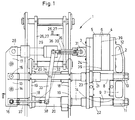
- FIG. 1 of the drawing shows a closing device 1 which is suitable for working with molds for producing hollow bodies made of thermoplastic material on blow molding machines, as well as for working with molds which are produced in a different way, for example by injection molding. can be used to manufacture objects made of thermoplastic.
- Such locking devices 1 can be in a known manner with the help of a special transport system, for example via parallelogram swing, between two different workstations, e.g. a tube extrusion station and a blowing station.
- a special transport system for example via parallelogram swing, between two different workstations, e.g. a tube extrusion station and a blowing station.
- the locking device 1 has a first mold mounting plate 2 and a second mold mounting plate 3, a mold half 4 or 5 being attached to each of these.
- the platen 2 sits on a yoke 7, which is rigidly attached to the rear end of a pull rod 8 and a push rod 9, for example anchored by a clamping screw 10 and 11.
- the pull rod 8 and the push rod 9 are aligned parallel to one another at a distance and extend exactly at right angles to the yoke 7, on the cantilever arm 12 of which the platen 2 is seated.
- Pull rod 8 and push rod 9 each engage another yoke 13 with their other end and form a frame 14 together with this and the yoke 7.
- pull rod 8 and push rod 9 - as already mentioned - with the yoke 7 through the clamping screw connections 10 and 11 each have an inherently rigid connection, they are each connected to the yoke 13 by a joint 15 and 16 oriented normal to the frame plane.
- the yoke 13 is also equipped with a cantilever 17 in such a way that both yokes 12 and 17 extend in the same direction sideways or upward from the frame 14.
- the pull rod 8 and the push rod 9 of the frame 14 are on the one hand in a frame 18th kept, which consists of two congruent end plates 19 and two these at a distance connecting sleeve pipes 20.
- the sections of tie rod 8 and push rod 9 protruding toward the yoke 7 from the frame 18 still form guide rails for displaceable sleeve pieces 21 and 22 of a crossbar 23 with a bracket 24 to which the second platen 3 is anchored.
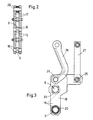
- the end plates 19 of the frame 18 have a substantially angular shape according to FIG. 3 with a vertical and a horizontal angle leg. While with the vertical angle leg both end plates 19 are connected to the two socket pipes 20, two supporting axes 25 are inserted in their horizontal legs, on which parallelogram arms 26 and 27 act, which are suspended, for example, in a boom (not shown). It can be seen from FIG. 3 that the parallelogram arms 26 have a curved or curved design, while the parallelogram arms 27 are straight.
- a power drive 29, for example a hydraulic or pneumatic piston-cylinder unit, is suspended on the cantilever arm 17 of the yoke 13 via a joint 28 which is parallel to the joints 15 and 16 as a closing motor.
- the frame 18 is a synchronous device 32 assigned.
- This has a lever 33 with the same arm, which is suspended on the frame 18 so as to be pivotable about an articulation 34.
- One arm of this lever 33 with the same arm is connected via a coupling rod 35 to the arm 24 of the crossbar 23, on which the platen 3 sits.
- the coupling rod 35 acts on the one hand on the joint 31, while on the other hand it is connected to the lever 33 of the same arm via a joint 36 of the same direction.
- a further coupling rod 37 is connected via a joint 38, which in turn engage in the joint 16 between the push rod 9 and the yoke 13 on the frame 14.
- the synchronizing device 32 is thus assigned to the closing device 1 such that a deformation of the frame 14 which occurs under the influence of the closing force effect can hardly lead to a displacement of the mold release plane relative to the calibration plane 39-39. This shift is thus compensated for by the special arrangement of the constant sound device.
- the arrangement and design of the frame 14 of the locking device 1 described above and its interaction with the two mold mounting plates 2 and 3 for the mold halves 4 and 5 of the mold 6 is of such a type that the deformations of the frame 14 caused by the action of the clamping force are used for this purpose not only can counteract an undesired inclined position of the mold parting plane, but also prevent an adverse displacement of the calibration position from the calibration plane 39-39. While the inclined position of the mold parting plane leads to excessive wear in the guide bushes of the mold 6 and also the cutting edges within the mold 6, an offset of the calibration position contributes to excessive wear on the blow mandrel and to improper calibration of the preform.
- FIGS. 4 and 5 show the essential system elements of the frame 14 and the synchronizing device 32 in the unloaded state, that is to say unaffected by the closing force effect brought about by the power drive 29.
- 5 shows the state of the system members of the frame 14 and the synchronizing device 32 when they are exposed to the influence of the closing force effect via the power drive 29.
- FIG. 5 of the drawing by way of example are intended to illustrate the extent to which an elastic elongation of the pull rod 8, an elastic shortening of the push rod 9 and a deflection of the yokes 7 and 13 occur under the influence of the closing force effect on the frame 14 and how these deformations in the direction of the mold clamping plates 2 and 3 or towards the mold 6 are compensated for with reference to the calibration planes 39-39.
- the synchronizing device 32 engages on the one hand in the joint 31 on the arm 24 of the crossbar 23 for the mold mounting plate 3, while on the other hand it engages the yoke 13 in Joint 16 for the push rod 9 is connected.
- the dimension a) corresponds to the length dimension of the overall system in the unloaded state.
- the dimensions b) and c) are used for the deflection of the yokes 7 and 13 in the loaded state.
- the dimension d) corresponds to the elongation of the pull rod 8 in the loaded state of the system, while the dimension e) corresponds to the shortening of the push rod 9 in the loaded state of the system.
- the dimension f) corresponds to the sum of the dimensions c), d) and e), while the dimension g) results from the dimension a) minus the dimension e).
- the dimension h) finally corresponds to the result of the dimensions f) and g) minus the dimension b).
- the yoke 13 Since the yoke 13 is in coupling connection via the joints 15 and 16 with the pull rod 8 and the push rod 9 and the cantilever arm 17 via the joint with the power drive 29, the yoke 13 and cantilever arm 17 can skew to a considerable extent without moment when the entire system is under load , as can be seen in exaggerated form in Fig. 5 of the drawing.
- the connection between the push rod 9 and the yoke 7, which is produced via the tensioning screw connection 11 can then be moved to the right in a corresponding manner - in accordance with dimension b) - ie the misalignment resulting from the length differences between the pull rod 8 and the push rod 9 that occur under load the yoke 7 with the cantilever 12 is compensated.
- the pull rod 8 is free of torque and consequently can no longer bend.
Landscapes
- Engineering & Computer Science (AREA)
- Mechanical Engineering (AREA)
- Manufacturing & Machinery (AREA)
- Moulds For Moulding Plastics Or The Like (AREA)
Applications Claiming Priority (2)
| Application Number | Priority Date | Filing Date | Title |
|---|---|---|---|
| DE4218260 | 1992-06-03 | ||
| DE4218260A DE4218260A1 (de) | 1992-06-03 | 1992-06-03 | Schließvorrichtung für Formen zum Herstellen von Gegenständen aus thermoplastischem Kunststoff |
Publications (2)
| Publication Number | Publication Date |
|---|---|
| EP0572839A1 true EP0572839A1 (fr) | 1993-12-08 |
| EP0572839B1 EP0572839B1 (fr) | 1996-08-07 |
Family
ID=6460280
Family Applications (1)
| Application Number | Title | Priority Date | Filing Date |
|---|---|---|---|
| EP93107868A Expired - Lifetime EP0572839B1 (fr) | 1992-06-03 | 1993-05-14 | Dispositif de fermeture de moule pour la fabrication d'articles moulés en matière thermoplastique |
Country Status (7)
| Country | Link |
|---|---|
| US (1) | US5388981A (fr) |
| EP (1) | EP0572839B1 (fr) |
| JP (1) | JPH06293058A (fr) |
| CN (1) | CN1097379A (fr) |
| AT (1) | ATE141074T1 (fr) |
| DE (2) | DE4218260A1 (fr) |
| ES (1) | ES2092178T3 (fr) |
Families Citing this family (8)
| Publication number | Priority date | Publication date | Assignee | Title |
|---|---|---|---|---|
| FR2739318B1 (fr) * | 1995-09-29 | 1997-11-21 | Gallay Sa | Presse de moulage par soufflage |
| US5840349A (en) | 1997-02-12 | 1998-11-24 | Graham Engineering Corporation | Rotary blow molding machine |
| CN1069572C (zh) * | 1999-04-29 | 2001-08-15 | 蔡桂森 | 塑料成型合模机构 |
| US6702567B2 (en) | 2001-11-14 | 2004-03-09 | R&B Machine Tool Company | Multi-station shuttle blow molding machine |
| CN1318198C (zh) * | 2002-09-20 | 2007-05-30 | 仿生株式会社 | 挤压机构和夹具机构 |
| US7220119B1 (en) | 2004-02-28 | 2007-05-22 | Force Pro | Pre-stressed tie rod and method of manufacture |
| US7611657B2 (en) * | 2006-11-30 | 2009-11-03 | Graham Engineering Corporation | Mold clamp assembly for blow molding machine and method |
| JP4864049B2 (ja) * | 2008-06-27 | 2012-01-25 | 株式会社フロンティア | 二軸延伸ブロー成形機の型締め機構 |
Citations (3)
| Publication number | Priority date | Publication date | Assignee | Title |
|---|---|---|---|---|
| EP0086385A1 (fr) * | 1982-02-16 | 1983-08-24 | HOOVER UNIVERSAL, INC (a Michigan corporation) | Procédé et dispositif de moulage |
| DE3924182C1 (en) * | 1989-07-21 | 1990-05-23 | Battenfeld Fischer Blasformtechnik Gmbh, 5210 Troisdorf, De | Closure device for moulds for thermoplastic components prodn. - comprising tensioning plates which locate with movable members on equalisation unit |
| EP0481259A1 (fr) * | 1990-10-15 | 1992-04-22 | Krupp Kautex Maschinenbau GmbH | Procédé et dispositif pour la fabrication de corps-creux en résine thermoplastique |
Family Cites Families (6)
| Publication number | Priority date | Publication date | Assignee | Title |
|---|---|---|---|---|
| US4421472A (en) * | 1981-08-31 | 1983-12-20 | R & B Machine Tool Company | Clamp for blow molding machine |
| US4560341A (en) * | 1982-02-16 | 1985-12-24 | Hoover Universal, Inc. | Apparatus for transporting sectional molds |
| DE3428823A1 (de) * | 1984-08-04 | 1986-02-13 | Krauss-Maffei AG, 8000 München | Vorrichtung zum herstellen von hohlkoerpern aus thermoplastischem material nach dem blasformverfahren |
| US4801260A (en) * | 1987-03-23 | 1989-01-31 | Graham Engineering Corp. | Rotary blow molding machine |
| DE3722340A1 (de) * | 1987-07-07 | 1989-01-19 | Battenfeld Fischer Blasform | Schliessvorrichtung fuer formen zum herstellen von gegenstaenden aus thermoplastischem kunststoff |
| US4998873A (en) * | 1988-10-03 | 1991-03-12 | R & B Machine Tool Company | Mold station for a blow molding machine |
-
1992
- 1992-06-03 DE DE4218260A patent/DE4218260A1/de not_active Withdrawn
-
1993
- 1993-05-14 ES ES93107868T patent/ES2092178T3/es not_active Expired - Lifetime
- 1993-05-14 AT AT93107868T patent/ATE141074T1/de active
- 1993-05-14 EP EP93107868A patent/EP0572839B1/fr not_active Expired - Lifetime
- 1993-05-14 DE DE59303375T patent/DE59303375D1/de not_active Expired - Fee Related
- 1993-05-27 JP JP5126323A patent/JPH06293058A/ja not_active Withdrawn
- 1993-06-02 US US08/070,579 patent/US5388981A/en not_active Expired - Fee Related
- 1993-06-03 CN CN93108219A patent/CN1097379A/zh active Pending
Patent Citations (3)
| Publication number | Priority date | Publication date | Assignee | Title |
|---|---|---|---|---|
| EP0086385A1 (fr) * | 1982-02-16 | 1983-08-24 | HOOVER UNIVERSAL, INC (a Michigan corporation) | Procédé et dispositif de moulage |
| DE3924182C1 (en) * | 1989-07-21 | 1990-05-23 | Battenfeld Fischer Blasformtechnik Gmbh, 5210 Troisdorf, De | Closure device for moulds for thermoplastic components prodn. - comprising tensioning plates which locate with movable members on equalisation unit |
| EP0481259A1 (fr) * | 1990-10-15 | 1992-04-22 | Krupp Kautex Maschinenbau GmbH | Procédé et dispositif pour la fabrication de corps-creux en résine thermoplastique |
Also Published As
| Publication number | Publication date |
|---|---|
| US5388981A (en) | 1995-02-14 |
| ES2092178T3 (es) | 1996-11-16 |
| DE4218260A1 (de) | 1993-12-09 |
| DE59303375D1 (de) | 1996-09-12 |
| JPH06293058A (ja) | 1994-10-21 |
| ATE141074T1 (de) | 1996-08-15 |
| CN1097379A (zh) | 1995-01-18 |
| EP0572839B1 (fr) | 1996-08-07 |
Similar Documents
| Publication | Publication Date | Title |
|---|---|---|
| EP0300223B1 (fr) | Dispositif pour fermer des moules, destiné à fabriquer des objets en matières synthétique thermoplastique | |
| DE69303731T3 (de) | Schliesseinheit für eine Spritzgussvorrichtung | |
| DE102017005404B4 (de) | Spritzgiessmaschine | |
| DE19501469C2 (de) | Holmlose Formschließeinrichtung | |
| DE112015003090T5 (de) | Öffnungs-/Schliessvorrichtung und Formvorrichtung | |
| DE69222188T2 (de) | Vorrichtung und verfahren zur herstellung von rohren und schläuchen | |
| EP0572839B1 (fr) | Dispositif de fermeture de moule pour la fabrication d'articles moulés en matière thermoplastique | |
| EP0646448B1 (fr) | Machine à mouler par injection pour traiter des matières plastifiables | |
| AT403777B (de) | Formschliessvorrichtung | |
| DE2100868A1 (en) | Mould closure/locking mechanism - partic for large blow moulding machines | |
| DE68909272T2 (de) | Vorrichtung zum vorder- und rückseitigen Greifen und Vorwärtsbewegen einer erweichten, zu formenden Kunststoffolie. | |
| EP0933181A2 (fr) | Dispositif de fermeture de moules pour la fabrication d'objets en résine thermoplastique | |
| DE4426521C1 (de) | Vorrichtung zum Schließen von Formen für die Herstellung von Gegenständen aus Kunststoff | |
| DE3924182C1 (en) | Closure device for moulds for thermoplastic components prodn. - comprising tensioning plates which locate with movable members on equalisation unit | |
| EP0192134A2 (fr) | Machine de moulage par injection avec dispositif d'enlèvement de la pièce moulée | |
| DE69523775T2 (de) | Spritzgiessmaschine mit offenem rahmen | |
| DE19615284C1 (de) | Formenschließvorrichtung | |
| EP1238780B1 (fr) | Procédé et dispositif pour la fabrication de tuyaux transversalement ondulés en matière thermoplastique | |
| EP2091675B1 (fr) | Dispositif de transfert pour une presse | |
| AT523575B1 (de) | Gusswerkzeug-Spannvorrichtung | |
| DE10342012A1 (de) | Spritzgießeinrichtung | |
| EP1848577B1 (fr) | Machine de moulage par injection pour l'usinage de matieres plastiques | |
| DE102009044506B4 (de) | Düsenanpressvorrichtung einer Spritzgiessmaschine | |
| DE4409262C1 (de) | Vorrichtung zum Blasformen von Hohlkörpern aus Vorformlingen | |
| DE2023094A1 (de) | Vorrichtung zum Herstellen von Hohlkoerpern aus thermoplastischem Kunststoff |
Legal Events
| Date | Code | Title | Description |
|---|---|---|---|
| PUAI | Public reference made under article 153(3) epc to a published international application that has entered the european phase |
Free format text: ORIGINAL CODE: 0009012 |
|
| 17P | Request for examination filed |
Effective date: 19930528 |
|
| AK | Designated contracting states |
Kind code of ref document: A1 Designated state(s): AT BE CH DE DK ES FR GB GR IT LI LU MC NL PT SE |
|
| 17Q | First examination report despatched |
Effective date: 19950725 |
|
| GRAH | Despatch of communication of intention to grant a patent |
Free format text: ORIGINAL CODE: EPIDOS IGRA |
|
| GRAA | (expected) grant |
Free format text: ORIGINAL CODE: 0009210 |
|
| AK | Designated contracting states |
Kind code of ref document: B1 Designated state(s): AT BE CH DE DK ES FR GB GR IT LI LU MC NL PT SE |
|
| PG25 | Lapsed in a contracting state [announced via postgrant information from national office to epo] |
Ref country code: NL Free format text: LAPSE BECAUSE OF FAILURE TO SUBMIT A TRANSLATION OF THE DESCRIPTION OR TO PAY THE FEE WITHIN THE PRESCRIBED TIME-LIMIT Effective date: 19960807 Ref country code: GR Free format text: LAPSE BECAUSE OF FAILURE TO SUBMIT A TRANSLATION OF THE DESCRIPTION OR TO PAY THE FEE WITHIN THE PRESCRIBED TIME-LIMIT Effective date: 19960807 Ref country code: GB Effective date: 19960807 Ref country code: DK Effective date: 19960807 |
|
| REF | Corresponds to: |
Ref document number: 141074 Country of ref document: AT Date of ref document: 19960815 Kind code of ref document: T |
|
| REF | Corresponds to: |
Ref document number: 59303375 Country of ref document: DE Date of ref document: 19960912 |
|
| ITF | It: translation for a ep patent filed | ||
| PG25 | Lapsed in a contracting state [announced via postgrant information from national office to epo] |
Ref country code: SE Effective date: 19961107 Ref country code: PT Effective date: 19961107 |
|
| REG | Reference to a national code |
Ref country code: ES Ref legal event code: FG2A Ref document number: 2092178 Country of ref document: ES Kind code of ref document: T3 |
|
| ET | Fr: translation filed | ||
| NLV1 | Nl: lapsed or annulled due to failure to fulfill the requirements of art. 29p and 29m of the patents act | ||
| GBV | Gb: ep patent (uk) treated as always having been void in accordance with gb section 77(7)/1977 [no translation filed] |
Effective date: 19960807 |
|
| PG25 | Lapsed in a contracting state [announced via postgrant information from national office to epo] |
Ref country code: AT Free format text: LAPSE BECAUSE OF NON-PAYMENT OF DUE FEES Effective date: 19970514 |
|
| PGFP | Annual fee paid to national office [announced via postgrant information from national office to epo] |
Ref country code: FR Payment date: 19970520 Year of fee payment: 5 Ref country code: ES Payment date: 19970520 Year of fee payment: 5 |
|
| PG25 | Lapsed in a contracting state [announced via postgrant information from national office to epo] |
Ref country code: LU Free format text: LAPSE BECAUSE OF NON-PAYMENT OF DUE FEES Effective date: 19970531 Ref country code: LI Free format text: LAPSE BECAUSE OF NON-PAYMENT OF DUE FEES Effective date: 19970531 Ref country code: CH Free format text: LAPSE BECAUSE OF NON-PAYMENT OF DUE FEES Effective date: 19970531 Ref country code: BE Effective date: 19970531 |
|
| PLBE | No opposition filed within time limit |
Free format text: ORIGINAL CODE: 0009261 |
|
| 26N | No opposition filed | ||
| BERE | Be: lapsed |
Owner name: BATTENFELD FISCHER BLASFORMTECHNIK G.M.B.H. Effective date: 19970531 |
|
| PG25 | Lapsed in a contracting state [announced via postgrant information from national office to epo] |
Ref country code: MC Effective date: 19971130 |
|
| REG | Reference to a national code |
Ref country code: CH Ref legal event code: PL |
|
| PG25 | Lapsed in a contracting state [announced via postgrant information from national office to epo] |
Ref country code: ES Free format text: LAPSE BECAUSE OF EXPIRATION OF PROTECTION Effective date: 19980516 |
|
| PG25 | Lapsed in a contracting state [announced via postgrant information from national office to epo] |
Ref country code: FR Free format text: LAPSE BECAUSE OF NON-PAYMENT OF DUE FEES Effective date: 19980531 |
|
| REG | Reference to a national code |
Ref country code: FR Ref legal event code: ST |
|
| REG | Reference to a national code |
Ref country code: ES Ref legal event code: FD2A Effective date: 20000301 |
|
| PGFP | Annual fee paid to national office [announced via postgrant information from national office to epo] |
Ref country code: DE Payment date: 20020511 Year of fee payment: 10 |
|
| PG25 | Lapsed in a contracting state [announced via postgrant information from national office to epo] |
Ref country code: DE Free format text: LAPSE BECAUSE OF NON-PAYMENT OF DUE FEES Effective date: 20031202 |
|
| PG25 | Lapsed in a contracting state [announced via postgrant information from national office to epo] |
Ref country code: IT Free format text: LAPSE BECAUSE OF NON-PAYMENT OF DUE FEES;WARNING: LAPSES OF ITALIAN PATENTS WITH EFFECTIVE DATE BEFORE 2007 MAY HAVE OCCURRED AT ANY TIME BEFORE 2007. THE CORRECT EFFECTIVE DATE MAY BE DIFFERENT FROM THE ONE RECORDED. Effective date: 20050514 |