EP0481259A1 - Procédé et dispositif pour la fabrication de corps-creux en résine thermoplastique - Google Patents
Procédé et dispositif pour la fabrication de corps-creux en résine thermoplastique Download PDFInfo
- Publication number
- EP0481259A1 EP0481259A1 EP91116386A EP91116386A EP0481259A1 EP 0481259 A1 EP0481259 A1 EP 0481259A1 EP 91116386 A EP91116386 A EP 91116386A EP 91116386 A EP91116386 A EP 91116386A EP 0481259 A1 EP0481259 A1 EP 0481259A1
- Authority
- EP
- European Patent Office
- Prior art keywords
- blow
- molded parts
- blow molded
- blow mold
- movements
- Prior art date
- Legal status (The legal status is an assumption and is not a legal conclusion. Google has not performed a legal analysis and makes no representation as to the accuracy of the status listed.)
- Granted
Links
- 238000000034 method Methods 0.000 title claims abstract description 32
- 238000004519 manufacturing process Methods 0.000 title claims description 5
- 229920001169 thermoplastic Polymers 0.000 title claims 2
- 239000004416 thermosoftening plastic Substances 0.000 title claims 2
- 239000000463 material Substances 0.000 title 1
- 238000000071 blow moulding Methods 0.000 claims abstract description 95
- 230000008569 process Effects 0.000 claims abstract description 6
- 239000012815 thermoplastic material Substances 0.000 claims abstract description 3
- 238000006073 displacement reaction Methods 0.000 claims description 110
- 238000009826 distribution Methods 0.000 claims description 27
- 230000008859 change Effects 0.000 claims description 15
- 230000000694 effects Effects 0.000 claims description 10
- 239000002699 waste material Substances 0.000 claims description 8
- 230000001105 regulatory effect Effects 0.000 claims description 3
- 230000015572 biosynthetic process Effects 0.000 claims 2
- 230000002349 favourable effect Effects 0.000 claims 1
- 230000007935 neutral effect Effects 0.000 description 15
- 238000001125 extrusion Methods 0.000 description 9
- 230000001360 synchronised effect Effects 0.000 description 7
- 238000010586 diagram Methods 0.000 description 4
- 238000007664 blowing Methods 0.000 description 2
- 230000001276 controlling effect Effects 0.000 description 2
- 238000001514 detection method Methods 0.000 description 2
- 239000012530 fluid Substances 0.000 description 2
- 230000004048 modification Effects 0.000 description 2
- 238000012986 modification Methods 0.000 description 2
- 238000000926 separation method Methods 0.000 description 2
- 230000007704 transition Effects 0.000 description 2
- 210000000078 claw Anatomy 0.000 description 1
- 230000005489 elastic deformation Effects 0.000 description 1
- 230000009916 joint effect Effects 0.000 description 1
- 238000007789 sealing Methods 0.000 description 1
- 230000007480 spreading Effects 0.000 description 1
- 238000003892 spreading Methods 0.000 description 1
- 238000009827 uniform distribution Methods 0.000 description 1
- 238000011144 upstream manufacturing Methods 0.000 description 1
- 238000003466 welding Methods 0.000 description 1
Images






Classifications
-
- B—PERFORMING OPERATIONS; TRANSPORTING
- B29—WORKING OF PLASTICS; WORKING OF SUBSTANCES IN A PLASTIC STATE IN GENERAL
- B29C—SHAPING OR JOINING OF PLASTICS; SHAPING OF MATERIAL IN A PLASTIC STATE, NOT OTHERWISE PROVIDED FOR; AFTER-TREATMENT OF THE SHAPED PRODUCTS, e.g. REPAIRING
- B29C49/00—Blow-moulding, i.e. blowing a preform or parison to a desired shape within a mould; Apparatus therefor
- B29C49/42—Component parts, details or accessories; Auxiliary operations
- B29C49/56—Opening, closing or clamping means
- B29C49/5605—Hydraulically operated, i.e. closing or opening of the mould parts is done by hydraulic means
-
- B—PERFORMING OPERATIONS; TRANSPORTING
- B29—WORKING OF PLASTICS; WORKING OF SUBSTANCES IN A PLASTIC STATE IN GENERAL
- B29C—SHAPING OR JOINING OF PLASTICS; SHAPING OF MATERIAL IN A PLASTIC STATE, NOT OTHERWISE PROVIDED FOR; AFTER-TREATMENT OF THE SHAPED PRODUCTS, e.g. REPAIRING
- B29C33/00—Moulds or cores; Details thereof or accessories therefor
- B29C33/20—Opening, closing or clamping
- B29C33/22—Opening, closing or clamping by rectilinear movement
Definitions
- the invention relates to a method and a device for producing hollow bodies made of thermoplastic material by means of blow molding, a preferably tubular preform being taken up by a blow mold having at least two blow molded parts and being expanded therein under internal pressure, and both parts of the blow mold between an open state in which they are have a distance from one another, and a closed state in which they abut one another and delimit a mold cavity, the contour of which corresponds to the shape of the preform widened by internal overpressure, are moved back and forth by at least one drive system causing the movements between these states.
- synchronizing devices are provided as an additional precaution, which bring about a defined movement sequence of the molded parts relative to a reference plane of the base frame.
- the arrangement is such that the synchronizing device has at least one mechanical connecting element which is not displaceably arranged on the base frame of the blow molding machine and by means of which the blow molded parts are kinematically coupled to one another. Due to the fixed arrangement of the connecting element on the base frame it is achieved that the closing and opening movements of the blow molded parts relative to the median plane of the preform or the article made therefrom run in opposite directions. It is thereby achieved with simple means that the molded parts close and open symmetrically and thus reach their closed or open state in defined positions.
- a gear wheel is rotatably arranged on an axis as a connecting element, which is fixedly attached to the base frame of the blow molding machine.
- the two blow molded parts have racks that mesh with the gear.
- a control lever is pivotally mounted on the base frame about a fixed axis.
- Rods are pivotally arranged on the two lever arms of equal length, the other end of which is movably attached to a blow molding part.
- blow molded parts are forcibly kinematically coupled to one another and to the base frame of the blow molding machine via such arrangements.
- Other synchronizing devices are also used which are familiar to any person skilled in the art and which require no further explanation. It can be z. B. to synchronous devices with an endless, flexible element, for. B. act a chain, a rope or the like. Which is guided by two rotatable, but not slidably mounted on the machine frame wheels, rollers or the like ..
- all embodiments have in common that they have at least one link which is arranged in a stationary, if rotatable, manner on the base frame of the blow molding machine and thus defines a reference plane relative to which the movements of the blow molded parts run symmetrically in opposite directions.
- the reference plane is generally chosen so that it coincides with the median plane of the preform.
- the blowing mandrel which interacts with the blow mold and the preform and through which i. a. the pressure medium required for expansion is passed into the blow mold
- Such a symmetrical movement is especially in the last phase of the closing process tion of the molded parts are often desirable, since the two blow molded parts in this phase comprise the preform hanging from an extrusion head or other suitable holding means and squeeze off the existing waste material in a known manner, the adjacent areas of the preform being welded to one another at the same time.
- the preform when the preform is in its receiving position in which it is received by the blow mold, it will hang on the extrusion head of an extrusion device.
- the preform which can also be produced in a manner other than extrusion, to be held in its receiving position by another holder until it has been taken up by the blow mold.
- the invention is therefore based on the object to design the method and apparatus of the type described in the introduction so that, if necessary, the closing and also the opening movements of the blow molded parts can run asymmetrically relative to the preform, in a simple and reproducible manner, while observing the requirements for Production of such hollow bodies necessary accuracy of the blow molding movements.
- the means required for this should be simple and inexpensive.
- the invention proposes to move the blow mold, at least temporarily, also in the direction during which the closing and / or opening movements take place, in a direction running parallel to the closing and opening movements.
- an additional movement is superimposed on the respective closing or opening movements of the blow molded parts, with the result that the blow molded parts move at different speeds and thus asymmetrically relative to a reference plane of the base frame of the blow molding machine, i.e. generally towards the preform or from the expanded hollow body move away.
- the displacement, which the blow mold experiences in its entirety, can take place according to the invention in different ways and also depends on the drive system which effects the closing and opening movements.
- the drive systems for the movements of the blow molded parts can differ from one another, inter alia, by the type of drive means or by the structure of the closing unit carrying the blow molded parts.
- a common drive means can be provided for the blow molded parts. It is also possible to assign a separate drive means to each blow molding. Hydraulic piston-cylinder units are mainly used as the drive means due to the high forces to be applied. In the following, therefore, without this being intended to be a limitation, it is predominantly spoken of hydraulic piston-cylinder units, it being understood that such units can also have a plurality of hydraulic cylinders acting in parallel.
- the common drive means is arranged between a first support plate carrying a blow molded part and a drive plate running parallel to it, which is connected to a second one by bars or the like the other side of the first carrier plate is rigidly connected, which carries the other blow molded part (see, for example, Fig. 1). Actuating the drive e.g.
- the displacement of the blow mold can take place according to the invention in that a link acting as a kinematic connecting element of the synchronizing device on the base frame, e.g. undergoes a shift, i.e. a change in its position, through an additional, independent drive system.
- a link acting as a kinematic connecting element of the synchronizing device on the base frame e.g. undergoes a shift, i.e. a change in its position, through an additional, independent drive system.
- the result of the displacement of the connecting element is that the entire movable unit, which includes the two carrier plates, the drive plate and the common drive means for the closing and opening movements, also undergoes a corresponding displacement.
- the desired path-time profile and / or speed profile of each blow molding part with respect to its opening and / or closing movements can be specified separately and the movements required for this of the drive system, which closes and opens the blow mold, and the additional drive system for the displacement of the blow mold depending on these path-time profiles and / or speed-time profiles can be determined. It will be expedient to provide a program for the path-time profile and / or speed profile for each blow molding part, it also being advantageous to provide a separate program for the closing movement and for the opening movement of the blow molding parts.
- the required closing and opening path-time profile can be determined in a simple manner, which is exclusively caused by the drive system for the closing and opening movements by calculating the distance-time profile of the blow molded parts to one another.
- the distance-time curve is the specification (target value) for the drive system causing the closing and opening movements.
- the displacement of the blow mold in its entirety required for the desired asymmetrical movement of the blow mold parts with respect to the center plane of the preform can be determined according to the invention by determining the distance of the center plane between the blow mold parts from the center plane of the preform or another reference plane of the base frame.
- the center plane between the blow molded parts corresponds to a plane which is half the distance between the blow molded parts, i.e. runs in the middle between the blow mold parts and relative to which the movements of the blow mold parts run in the same opposite way, that is to say run symmetrically.
- the resulting distance-time profile of the two middle planes corresponds to the required displacement of the blow mold and is the specification (target value) for the additional drive system causing the displacement. It is necessary to determine the direction of the shift in addition to the extent, since the blow mold can be shifted in both directions.
- the asymmetrical movements of the blow mold parts can thus be achieved by separately specifying the path-time curve or the speed curve of the individual blow mold parts by superimposing the closing or opening movements and shifting the blow mold.
- the drive means of the drive system causing the displacement of the blow mold act at a location other than on the connecting element of the synchronizing device.
- the drive means may be appropriate to arrange the drive means between a blow molding part and the base frame of the blow molding machine.
- the additional drive system must bring about a displacement path-time curve which corresponds to the respective path-time curve of the blow molded part which is connected to the additional drive system.
- a piston-cylinder unit is arranged in each case between the base frame and the carrier plates carrying the blow molded parts. Due to the joint action of the hydraulic cylinders with hydraulic working medium, the blow molded parts move towards or away from the preform, in general a synchronizing device of the type described in the introduction is also provided in order to produce symmetrical movements of the blow molded parts relative to the preform. Even with such a blow molding machine, the blow mold in its entirety can additionally be shifted in order to achieve the desired asymmetrical movements of the blow molded parts, for example by B. the connecting element experiences a shift.
- a displacement of the blow mold also corresponds to a displacement or change in length of the synchronizing device with a path-time profile which corresponds to the distance between the center plane of the blow mold parts and the center plane of the preform in such blow molding machines.
- the carrier plates of the blow molded parts and the parts of the hydraulic piston-cylinder unit attached to them are also displaced. This is possible because the spaces of the cylinders for the opening and closing movements are connected to one another via the line system for the hydraulic medium. It can therefore be caused by a relatively slight application of force by an actuator, e.g. can also be designed as a hydraulic piston-cylinder unit, causing a displacement of the two carrier plates in one direction.
- an actuator e.g. can also be designed as a hydraulic piston-cylinder unit, causing a displacement of the two carrier plates in one direction.
- the drive system which causes the closing and opening movements of the blow mold parts, is no longer completely uninvolved in shifting the blow mold, since the asymmetrical movements of the blow mold parts thereby caused, relative to the reference plane, changes in the distances to be traveled by the blow mold parts and in each case associated with them Result in drive means.
- a shift in the blow mold will therefore have a direct effect on the stroke of the hydraulic piston and cylinder unit of the individual blow mold parts to be carried out. It goes without saying that the piston-cylinder units have a maximum stroke which enables such displacements.
- blow molding machine with a drive means for each blow molded part to have the additional drive system act directly on a blow molded part or on a carrier plate.
- the additional drive system executes the predetermined movements of the blow molded part connected to it, so that its movements are fixed with respect to the base frame of the blow molding machine.
- Sufficient hydraulic working medium is therefore supplied to the drive means assigned to this blow molding part that the blow molding part can carry out the movement with respect to the base frame which is forced by the additional drive system.
- blow molding machines which have a separate hydraulic piston-cylinder unit as the drive means for each blow molded part
- the possibility of causing the displacement of the blow mold required for asymmetrical movement of the blow mold parts in that the drive means total hydraulic working medium to be supplied is divided accordingly by suitable means, so that the desired asymmetrical movements of the blow mold parts are effected relative to the reference plane, the movements of the blow mold parts relative to one another also being unaffected by the distribution here.
- the invention therefore proposes to distribute the total amount of hydraulic working medium supplied, which is determined by the determined course of movement of the blow mold parts relative to one another, as a function of the extent of the required displacement of the blow mold, so that the necessary displacement of the blow mold occurs without the need for an additional drive system. It is important that the distribution of the volume flows takes place only after the dimensioning of the total volume flow of hydraulic working medium required for the closing and / or opening movements of the blow mold parts to one another, so that the closing and / or opening movements of the blow mold parts to one another remain unaffected by the displacement of the blow mold .
- the procedure is such that a measuring sensor for the distance covered or for the speed, which measures a value for the actual displacement of the blow mold, is arranged on the connecting element of the synchronizing device which can be adjusted in terms of position or length.
- the displacement or change in length of the connecting element corresponds to the displacement of the blow mold relative to the base frame of the blow molding machine.
- This actual displacement is compared with the target displacement, which is determined from the path-time profile of the distance of the median plane between the blow mold parts from the median plane of the preform and corresponds to a specific distribution of the hydraulic working medium, depending on which occurs Deviation, the distribution of the amount of working medium supplied is corrected.
- a sensor for the distance covered or the speed on a blow molded part, which detects the actual movement of this blow molded part.
- the distribution of the working medium is corrected as a function of a deviation of the measured value from the specified path-time profile and / or speed profile of this blow molding.
- a synchronizing device which can be freely set, is not absolutely necessary for the actual value acquisition.
- the asymmetrical movements of the blow molded parts are also composed of a superposition of the closing or opening movement with the displacement of the blow mold in such blow molding machines.
- the closing or opening movement of the blow molded parts to each other is realized by the hydraulic working medium supplied as a whole, regardless of how it is distributed among the individual drives.
- An unequal distribution corresponds to an increase in the distance covered by one and a decrease by the same amount in the distance covered by the other blow molded part.
- this division of the paths corresponds to a movement sequence of a displacement of the two blow mold parts and thus the blow mold in one direction.
- the embodiments of the invention described here therefore have in common that the predetermined asymmetrical movements of the blow mold parts with respect to a reference plane of the base frame are composed on the one hand of the closing or opening movement of the blow mold parts and an overlaid displacement of the blow mold in its entirety on the other hand.
- an additional drive system is used which engages a blow molded part or a connecting element of the synchronizing device and carries out the movement corresponding to the predetermined additional displacement of the blow mold.
- the additional drive means is arranged on a blow molding part or on another element of the blow molding device whose movements follow
- the use of a synchronizing device is not absolutely necessary.
- the connecting element can be fixed in a simple manner using mechanical means, for example by means of a bolt or another element which, in the fixed position of the connecting element or a part connected thereto, engages in a recess provided on this element or part.
- the program for the path-time profile of the blow molded parts during the closing movement in such a way that it has two sections, of which the section associated with the end of the closing phase leads to movements which meet the requirements for squeezing and Fulfill the preform and, if necessary, run symmetrically to a component of the blow mold that does not participate in the opening and closing movements.
- This last program section should be able to be carried out essentially independently of the previous asymmetrical movements of the blow molded parts.
- the movements of the blow mold parts to different reference planes can be carried out in a simple manner without having to make laborious adjustments to the blow mold, e.g. to the extrusion head.
- the preform may be closed at its free end, in order to prevent the inner surfaces of the tubular preform from coming into contact with one another.
- the introduction of supporting air and pre-expansion are known measures, the detailed description of which is not necessary.
- the blow mold in its entirety is displaceable relative to the frame of the blow molding machine, it may be necessary to arrange devices which are arranged in a predetermined position relative to the blow mold, e.g. B. the device for supplying the blowing or supporting air, also slidable. This can e.g. B. done in that such devices are firmly connected to one of the blow molded parts or are moved together with the connecting element.
- a common drive means of the blow molded parts is provided for the closing and opening movements.
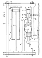
- the common hydraulic drive means 17 has a piston 14 which is displaceable in a cylinder 15, the piston rod 20 of which is connected to a carrier plate 12b which carries the one blow molded part 10b.
- the cylinder 15 is arranged on a drive plate 16 which is rigidly connected to the other carrier plate 12a by means of spars 18 which run through openings and guides 19 in the carrier plate 12b.
- the carrier plate 12a is arranged on the other side of the carrier plate 12b and carries the blow molded part 10a.
- the spars 18 and thus also the carrier plate 12a and the drive plate 16 are displaceably mounted on the base frame 4 by means of stands 5 which have corresponding guides. Further details of the blow molding machine are not shown for reasons of clarity.
- the blow molding device has a synchronizing device 30 with a gear 25 rotatably mounted on an axis 26, which meshes with toothed racks 28a and 28b, which in each case on the drive plate 16 or on the carrier plate 12b are attached. It is of course also possible to arrange the synchronizing device directly between the carrier plates 12a, 12b, so that the gear meshes with racks, which are each connected to a carrier plate. The same effect is achieved with both arrangements.
- the axis 26 is mounted in a holder 32, which can be displaced with respect to the base frame via bars 33 parallel to the opening and closing movements of the blow molded parts 10a, 10b. The displacement is effected by an additional drive means 38 designed as a hydraulic reciprocating piston, the piston rod 36 of which is connected to the holder 32 and the cylinder 35 of which is connected to the base frame 4.
- the extrusion head 22 of an extrusion device 23 is arranged above the blow molding parts 10a, 10b, from which the generally tubular preform 24 is extruded into the space between the two blow molding parts 10a, 10b of the then open blow mold.
- the preforms can be extruded from the extrusion head continuously or discontinuously.
- a preform 24 As soon as a preform 24 has a length required for the production of a hollow body, it is taken up by the blow mold by moving the blow mold parts 10a, 10b from their open state shown in FIG. 1 of the drawing by the drive means 17 into their closed state so that the mutually facing boundary surfaces 11 a, 11 abut each other and a mold cavity is delimited, within which the preform is expanded.
- actuation of the drive means 17 in the closing direction has the effect that, with the holder 32 of the synchronizing device 30 stationary, the carrier plate 12b is moved to the left and the drive plate 16 with the carrier plate 12a is moved to the same extent to the right, whereby the blow molded parts move symmetrically to a reference plane of the base frame 4, which generally corresponds to the central plane 9 of the preform 24.
- the center plane of the preform is therefore assumed to be the reference plane, without any limitation.
- the position of the gear wheel 25 of the synchronizing device 30 thus determines the position of the part dividing the distance between the two blow mold parts 10a, 10b Plane, which therefore always, ie regardless of the absolute position of this plane, runs in the middle between the two blow mold parts 10a, 10b or, in the case of an asymmetrical configuration thereof, in the middle between the two carrier plates 12a, 12b.
- This displacement of the blow mold is completely independent of the opening and closing movements of the blow mold parts caused by the common drive means 17, so that the displacement z. B. can also be carried out when the blow molded parts experience no movement relative to each other or are in their closed or open state.
- a path-time programmer 60 is provided, in which the desired path-time profiles and / or speed profiles of the blow mold parts 10a, 10b z. B. can be entered with respect to the median plane 9 of the preform. This means that the distance traveled by one of the blow mold parts is entered into the programmer 60 over the time and / or the speed at which the distance is covered.
- the programmer 60 is connected to a computing unit 62 which calculates the desired distance of the blow mold parts 10a, 10b from one another and / or their target speed relative to one another from the values entered in the programmer 60 and the resulting desired movements of the blow mold parts and a comparison and control device 49 as a target value.
- This device 49 controls, via the signal line 53, a valve 54 which is connected via lines 55, 56 to the cylinder 15 of the common drive system 17 and through which the volume flow of the hydraulic working medium, which is pumped to or returned from the cylinder 15, which corresponds to the closing and / or opening movement of the blow molded parts.
- the actual distance between the blow mold parts 10 a, 10 b is detected via a measuring sensor 50, which interacts with the blow mold parts 10 a, 10 b and is fed via the signal line 51 to the comparison and control device 49, which, if the actual value deviates from the target value Position of valve 54 corrected accordingly.
- the direct detection of the distance between the blow molded parts or the carrier plates assigned to them is cheaper than the separate detection of the paths of the blow molded parts or their associated carrier plates relative to the base frame and the calculation of the distance from the paths. In the latter case, elastic deformations of the parts of the machine that absorb the closing forces can lead to inaccurate results.
- the programmer 60 is connected to a computing unit 64, in which the desired distance between the central plane of the blow molded parts and the central plane 9 of the preform 24 is calculated. Relative to the first-mentioned central plane, which is half the distance between the blow molded parts, i.e. in the middle between these runs, the movements of the blow molded parts are symmetrical, i.e. opposite.
- the distance-time profile of the two center planes to one another corresponds to the target value of the overlapping displacement and is predefined by the computing unit 64 via a line 45 to a comparison and control unit 42, which controls a valve 44 via the signal line 43, which controls the valve via the lines 46, 41 supplies the volume flow of hydraulic working medium required for the displacement to the drive means 38.
- the actual position (actual value) of the gear wheel 25 is detected by a displacement sensor 37 which interacts with the holder 32. Via the signal line 39, the displacement sensor 37 is connected to the comparison and control unit 42, which corrects the position of the valve 44 as a function of a deviation of the actual value from the target value specified by the computing unit 64.
- the axis 26 of the gear 25 is always at the same distance from the central plane of the blow molded parts, so that the determined distance between the central plane of the blow molded parts and the central plane 9 of the preform 24 corresponds to the required displacement of the blow mold and thus of the gear 25 with respect to the base frame.
- FIG. 2 shows the displaceable synchronous device on a larger scale than in FIG. 1.
- FIG. 3 shows another embodiment of a displaceable synchronizing device 30.
- This embodiment has a control lever 81 which is pivotably arranged on the axis 26 of the displaceable holder 32.
- lever rods 83a and 83b are articulated at the opposite ends of the control lever 81 and are connected to the drive plate 16 and the carrier plate 12b, respectively.
- This arrangement also ensures that the carrier plate and drive plate 16 move symmetrically to the axis 26, as when using a gearwheel meshing with toothed racks.
- the embodiment according to FIG. 4 differs from that according to FIG. 1 in particular in that the additional drive means 31 is arranged between the base frame and the drive plate 16, so that the piston rod 36 of the cylinder 35 attached to the base frame acts directly on the drive plate 16.
- the result of this arrangement is that the movements of the piston guided in the cylinder 35 are transmitted directly to the unit having the drive plate 16 and the carrier plate 12a.
- the movements of this unit 16, 12a therefore run synchronously with those of the piston guided in the cylinder 35.
- the latter also applies to the carrier plate 12b and thus to the blow molded part 10b carried by it, as long as the piston 14 and cylinder 15 of the common drive means 17 do not move relative to one another for the opening and closing movements.
- the carrier plate 12b executes a resulting movement with the blow molding part 10b, which movement is composed of the movement components of the additional drive means 31 and the common drive means 17.
- the arrangement of the common drive means 17 for opening and closing movements of the blow molded parts and its regulation correspond to the embodiment according to FIG. 1. Since the additional drive means 31 now acts on the drive plate 16 and thus causes its movements and that of the carrier plate 12a directly, Program generator 60, in which the path-time profiles of the individual blow mold parts are stored, the signal-line 45 of the comparison and control unit 42 the path-time profile of the blow mold part 10 a to the drive means 31 as the desired value.
- the additional drive means 31 engage directly on one of the carrier plates 12a or 12b.
- the program generator 60 would specify to the controller 42 the path-time profile of the blow molded part 10a or 10b connected to the additional drive means 31.
- the comparison and control unit 42 controls via the signal line 43 the valve 44, which determines the volume flow of hydraulic working medium required for the displacement of the drive plate 16.
- the displacement of the drive plate causes a corresponding movement of the blow molded part 10a due to the rigid connection through the bars 18 to the carrier plate 12a.
- the actual position of the drive plate 16 is detected by a displacement sensor 34 and input to the controller 42 as an actual value via the signal line 39.
- the comparison and control unit 42 corrects the position of the valve 44 if necessary.
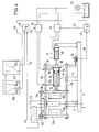
- FIGS. 5 to 7 show exemplary embodiments of blow molding devices in which drive systems are provided which have a separate drive means for each blow molded part, although there is otherwise broad agreement with the exemplary embodiment according to FIG. 1.
- FIGS. 5-7 the same parts are given the same parts, compared to those in FIGS. 1-4 are provided with 100 higher reference numerals.
- the blow molding machine according to FIG. 5 has two blow molding parts 110a, 110b, which are arranged on carrier plates 112a, 112b.
- a gear 125 is rotatably provided on an axis 126, which meshes with two toothed racks 128a, 128b, which are each connected to a carrier plate 112a or 112b.
- the holder 132, on which the gear 125 is arranged, can be displaced via an additional drive means 138 on the base frame parallel to the opening and closing movements of the blow molded parts.
- the control device for controlling the movement sequence of the blow molded parts largely corresponds to the control device according to FIG. 1. Since a separate drive means 117a, 117b is provided in each case, the hydraulic working medium to be supplied is downstream in the flow direction for the dimensioning of the given movements of the blow molded parts 110a, 110b required amount of hydraulic working medium provided valve 154 divided into two partial flows 156a, 156b. The hydraulic working medium displaced from the cylinders 115a, 115b is brought together in the flow direction upstream of the valve 154.
- the hydraulic drive means 117a, 117b are accordingly connected to one another via the lines 155a, 155b and 156a, 156b in such a way that the space 102a in front of the piston 114a with the space 102b in front of the piston 114b and the space 103a behind the piston 114a with the Space 103b is connected behind the piston 114b of the respective lifting cylinder 115a, 115b.
- the total amount of hydraulic working medium required for the predetermined closing movement of the blow molded parts is set by the valve 154 and conducted under pressure into the spaces 103a, 103b of the respective drive means 117a, 117b via the line 181 and the branch lines 156a, 156b , while at the same time the hydraulic working medium is discharged from the spaces 102a, 102b of the drive means via the branch lines 155a, 155b and the collecting line 183.
- the holder 132 of the gear wheel 125 is stationary, the total amount of hydraulic working medium supplied is evenly distributed to the drive means 117a, 117b due to the symmetrical movements of the blow molded parts which are thereby forced.
- the drive means 117a receives more hydraulic working medium, while the drive means 117b receives less accordingly, so that one piston 114a corresponding to the more supplied quantity of hydraulic working medium an additional, the other piston 114b according to the less supplied quantity one by the additional Reduced path of the piston 114a runs through with the effect that the two blow mold parts 110a, 110b and thus the blow mold experience a displacement in the direction of the displacement of the holder 132 independently of the continuing closing movement of the blow mold parts 110a, 110b.
- the hydraulic working medium is supplied to the spaces 102a, 102b, where it may experience a distribution corresponding to the displacement of the gear 125.
- the position of the gear wheel 125 also directly defines the position of the distance between the two blow molded parts 110a, 110b dividing middle plane. This means that the axis 126 is positioned in this central plane.
- gear 125 is in its neutral position. That is, the above-mentioned central plane of the blow molded parts coincides with the central plane 109 defined by the preform 124.
- FIG. 6 corresponds to that of FIG. 5, but the displacement of the blow mold is brought about by an additional drive means 131, which is arranged between the base frame 104 (not shown here) and the carrier plate 112b.
- the additional drive means 131 must therefore pass through the path-time profile of the blow molded part 110b predetermined by the programmer 160.
- the control elements provided for this drive means 131 therefore correspond to those of the blow molding device according to FIG. 4. If, for example, according to the program stored in the program generator 160, the blow molding part 110b is to perform a slower movement relative to the central plane 109 of the preform 124, the additional load is applied in this way Drive means 131 that the carrier plate 112b executes the movement assigned to it by the program.
- each of the two drive means 117a, 117b has its own valve analogous to valve 154 and / or its own control circuit would be unsuitable, since in particular in the last phase of the closing process, within which increased forces, e.g. B.
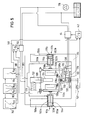
- FIG. 7 shows a further possibility of causing the displacement of the blow mold in addition to the opening and closing movements of the blow mold parts 110a, 110b in a blow molding machine which has a separate hydraulic drive means for each blow mold part.
- the displacement of the connecting element of the synchronizing device or the forced implementation of the path-time profile of a blow molded part by means of an additional drive means that the total amount of hydraulic working medium supplied is distributed unevenly in such a way that the respective one The amount of hydraulic working medium supplied to the drive means corresponds to the predetermined movement of the respective blow molded part in accordance with the value entered in the programmer 160.
- the predetermined movements of the blow molded parts relative to one another are brought about by the total amount of hydraulic working medium supplied in accordance with the target value determined by the computing unit 162, the amount being measured by the valve 154 before the division into the branch lines 155a, 155b, 156a, 156b.
- the distribution of the working medium is not necessarily brought about by an additional force acting on at least one of the blow molded parts, but by a distributing device.
- a program generator 160 is provided, in which the path-time profiles or speed profiles for each blow molding 110a, 110b relative to e.g. the middle plane 109 of the preform can be entered.
- the resulting distance-time profile or speed profile of the blow mold parts relative to one another is determined in the computing unit 162 and is given to a comparison and control device 149, which controls the valve 154, by means of which the hydraulic quantity required for the respectively predetermined movement Working medium is set.
- the programmer 160 is also connected to a computing unit 164, in which the displacement of the blow mold required for the desired asymmetrical movement of the blow mold parts with respect to the central plane 109 of the preform is determined, based on a specific distribution of the total hydraulic working medium supplied to the two drive means 117 a, 117b corresponds.
- the relations according to which the distribution has to be carried out are specified to a comparison and control unit 142, which controls a quantity distribution valve 171 for the supplied volume flow 181 and a quantity distribution valve 173 for the displaced volume flow 183 of the hydraulic working medium, the name of the supplied or displaced volume flows relates to the closing movements of the blow molded parts. With the opening movements, the flow direction of the volume flows is opposite.
- the drive means 117a, 117b are connected via lines 156a, 156b and 155a, 155b to the respective outputs or inputs of the quantity distribution valves 171 and 173, respectively.
- a measuring sensor 137 is provided, which is connected via the signal line 139 to the comparison and control device 142, which depends on a deviation of the actual value from the target calculated in the computer 164 - Corrected the valve position of the volume distribution valves 171, 173. It may be expedient to couple the volume distribution valves to one another via a line 174, since the displaced volume flow corresponds at least approximately to the supplied working medium due to the almost complete incompressibility of the hydraulic working medium.
- the sensor 137 is arranged on a displaceable synchronizing device 130, the structure of which corresponds to the synchronizing devices in FIGS. 1, 2 or 5, so that the displacement of the gear 125 corresponds to the actual displacement of the blow mold.
- the position of the axis 126 directly defines the median plane of the blow mold, since it runs in this median plane.
- the sensor z. B. to arrange on a blow molded part or a carrier plate, but then the valves 171, 173 are set depending on the comparison of the actual position of the corresponding blow molded part with the path-time curve for this blow molded part.
- blow mold is displaced by an additional drive system, which leads to a corresponding distribution of the hydraulic working medium, additionally to provide a distribution device for the total amount of hydraulic working medium supplied.
- the setting of the required quantity distribution valves e.g. can correspond to the volume distribution valves 171, 173, depending on the displacement of the connecting element.
- synchronizing devices 30, 130 are shown in the corresponding figures without the possibility of locking.
- Locking movable synchronizing devices is, however, possible by conventional means, e.g. possible by means of bolts or claws engaging in the recess or by means of frictional engagement, which therefore need not be shown in more detail.
- FIGS. 8-10 also show exemplary embodiments of blow molding devices in which each blow molded part is provided with a separate drive means.
- the two exemplary embodiments according to FIGS. 8 and 9 largely agree with the embodiment according to FIG. 5, but in principle also with that according to FIG. 1, so that in FIGS. 8 and 9 parts which correspond to those of the exemplary embodiments already described, are provided with the same reference numerals, but 100 more than in FIG. 5 and thus 200 more than in FIG. 1.
- a synchronizing device having a gearwheel 225 and two toothed racks 228a, 228b is also provided, but the holder 232, which carries the axis 226 for the gearwheel 225, is fixedly attached to the machine frame 204.
- the holder 232 which carries the axis 226 for the gearwheel 225, is fixedly attached to the machine frame 204.
- one of the two racks namely the rack 228a
- the cylinder 235 of this drive means 238 is fixedly connected to the carrier plate 212a for the blow molding 210a.
- the movement of the blow molded parts 210a, 210b is thus not caused by a displacement of the gear 236, but by changing the effective length of another connecting element of the synchronizing device, namely the rack 228a .
- the effective length is changed by appropriately acting on the piston 240 guided in the cylinder 235 by the valve 244, which is controlled in the manner already described in connection with FIGS. 1 and 5 by a comparison and control unit 242.
- the latter is connected via the line 245 to the computing unit 264, in which the respective desired distance between the central plane of the blow molded parts and the central plane 209 of the preform 224 is calculated.
- the position of the median plane of the blow molded parts is determined by the position of the piston 240 relative to the cylinder 235 and thus to the carrier plate 212a carrying this cylinder. 8, the piston 240 takes its neutral, i.e. middle position in which the center plane of the two blow mold parts 210a, 210b coincides with the center plane 209 defined by the preform 224. Acting on the cylinder 235 on one of the two sides of the piston 240 has the result of the longitudinal displacement of the rack 228a which results in a rectified displacement of the two blow molded parts 210a, 210b, so that a displacement of e.g. B. the gear 125 in the embodiment according to FIG.
- FIG. 9 corresponds in all essential details with that of FIG. 8, so that the same reference numerals are used for corresponding parts.
- the only difference between the two versions relates to the design of the synchronizing device, which in the case of FIG. 9 consists of a chain, a cable or a similar endless flexible part 225 which is arranged around two wheels, disks or the like which are at a distance from one another chen 226a, 226b is performed.
- the two wheels or the like 226a, 226b are rotatably mounted on the machine frame 204.
- the arrangement is such that the directions in which the chain or the like 235 moves run parallel to the directions in which the two blow mold parts 210a, 210b execute their opening and closing movements.
- Both blow molded parts 210a, 210b or their carrier plates 212a, 212b are connected to the endless part 225 via essentially rigid connecting elements 228a, 228b such that the connecting element 228a with one section 225a and the other connecting element 228b with the other section 225b of the endless Part 225 is connected.
- the connecting element 228a is attached to the piston rod 236 of a piston which is guided in a cylinder 235. In the embodiment corresponding to FIG. 8, the latter is firmly connected to the carrier plate 212a of the blow molded part 210a.
- the same mode of operation results as in the exemplary embodiment according to FIG. 8.
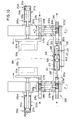
- each of the two carrier plates 312a, 312b is provided with a rack 328a, 328b of a synchronous system, but the racks 328a, 328b are, however, attached to the side of the carrier plate facing away from the respective blow molding 310a, 310b.
- the toothings are arranged on opposite sides in such a way that the toothing of the toothed rack 328a is turned towards the viewer on the basis of the illustration in FIG.
- a gear wheel 325a, 325b is assigned to each of the two toothed racks 328a, 328b.
- Each gearwheel is fixedly connected to a shaft 326a or 326b, which ends downward from the respectively associated gearwheel 325a or 325b in a region which, based on the illustration in FIG. 10, is located below the carrier plates 312a, 312b or the blow mold parts 310a, 310b carried by these lies.
- Each of the two shafts 326a, 326b has a gear 325a 'and 325b' at its lower end.
- a common rack 390 is assigned to these two gearwheels 325a ', 325b'.
- the latter has two rack sections 392a, 392b, which are connected to one another by a cylinder-piston unit 338.
- the piston 340 guided in the cylinder 335 of this unit is provided with a piston rod 336, one end of which is fixedly connected to the rack section 392a, which meshes with the gear 325a '.
- the other end of the piston rod 336 carries a part 397 of a displacement transducer 337, through which the actual position (actual value) of the piston 340 to the cylinder 335 is detected and is passed via a line 339 to a comparison and control unit, which for example is the unit 242 corresponds to FIG. 9.
- the end region of the piston rod 336 which carries the part 397 of the displacement transducer 337 is passed through the end boundary 396 of the cylinder 335, the opening required for this purpose being provided in the end boundary 396 with sealing means which prevent the hydraulic pressure medium from escaping.
- the connection between the section 392 of the rack 390 and the cylinder 335 takes place via a connecting rod 398 and a housing 393 which is fixedly connected to the cylinder 335 and is provided with a slot-like passage for the part 397 of the displacement sensor 337.
- the rack 390 represents the length-adjustable kinematic connecting link of the elements of the synchronizing device 330 assigned to the blow molding parts 310a, 310b.
- This rack 390 is arranged so that it can be moved back and forth in the direction of its longitudinal axis can follow the rotational movements of the two gears 325a ', 325b' by executing a corresponding longitudinal displacement.
- the cylinder-piston unit 338 has the function of the drives 238 of the two exemplary embodiments according to FIGS. 8 and 9. Accordingly, the two lines 341 and 346 are connected to a valve which fulfills the function of the valve 244 in the exemplary embodiment according to FIGS. 8 and 9. Including the displacement sensor 337 and the connecting line 339, the circuit then results, which is also shown in FIGS. 8 and 9. This also applies to the other parts and arrangements, which can also be designed in the manner corresponding to FIGS. 8 and 9, but also in a manner corresponding to FIG. 7, in which case, however, the unit 338 would only have the function of a position transmitter.
- the guide means 395a, 395b for the rack 328a and 328b shown in FIG. 10 of the drawing, the guide means 398a, 398b for the rack sections 392a, 392b and the guide means 399a, 399b for the shaft 326a and 326b are each fixed on the machine frame 304 appropriate.
- FIG. 11 shows possible path-time profiles A (t), B (t) of the individual blow molded parts 10a; 110a; 210a; 310a and 10b; 110b; 210; 310b with respect to the neutral plane 9; 109; 209; 309 of the preform, the resulting distance-time profile S (t) of the blow mold parts relative to one another and the resulting required displacement profile V (t) (dashed line) of the blow mold in its entirety is shown schematically.
- the path is plotted on the horizontal axis, the zero in terms of value on the neutral central plane 9; 109; 209; 309 lies.
- the path-time profiles A (t), B (t) are e.g. B. in programmer 60; 160; 260 entered.
- the distance-time profile S (t) of the blow mold parts 10a, 10b; 110a, 11 ob; 210a, 210b; 310a, 310b calculated to each other.
- the distance-time profile V (t) of the central plane of the blow mold parts 10a, 10b; 110a, 110b; 210a, 210b; 310a, 310b to neutral plane 9; 109; 209; 309 of the preform determined.
- the distance-time curve V (t) corresponds to the displacement-time curve of the blow mold or the central plane of its blow mold parts.
- the blow molded parts move symmetrically, ie at the same speed, in the direction of the neutral plane 9; 109; 209; 309 of the preform, which coincides with the central plane of the blow mold.
- the speed at which the blow mold parts approach each other is twice as high in time period 1 as the speed of an individual blow mold part with respect to the reference plane 9; 109; 209; 309.
- the blow molded part 10a, 110a, 210a, 310a does not move, although the closing speed of the blow molded parts relative to one another remains unchanged.
- the connecting element of the synchronizing device moves from its neutral position with the result that the central plane of the blow mold is displaced in the direction of the blow mold part 10a, 110a in accordance with the extent of this movement, following the line V (t).
- the additional drive system that drives the displaceable connecting element in the embodiments according to FIGS. 1, 3 and 5 must therefore travel exactly this distance V (t). In the embodiment according to FIG. 5, this is achieved in that the total working medium supplied reaches only the drive means which is assigned to the blow molding to be moved.
- the blow molded part 10b, 110b, 210b, 310b experiences no movement under corresponding conditions, so that the reciprocal operating states of phase 11 are present.
- the additional drive means performs the predetermined movement of the blow molding part 11 Ob connected to the additional drive means, this movement simultaneously also the lifting movement of the Corresponds to drive means 131 for the closing movement and the drive means for the stationary blow molded part does not receive any hydraulic working medium.
- the quantity distribution valve in phase 11 or 111 would be set such that the valve slide 171 or the corresponding functional element completely closes the supply line assigned to the stationary blow molding part, so that the previously dimensioned one Amount of hydraulic working medium is led exclusively to the drive means which is connected to the blow mold part in each case moved.
- the blow molding part 10b, 11 Ob, 210b, 310b moves faster in the direction of the central plane 9, 109, 209, 309 or zero plane O, while in the last time period VI the blow molding part 10a, 110a, 210a, 310a moves faster .
- the blow mold undergoes an additional displacement at a speed which corresponds to half the sum of the speeds of the individual blow mold parts and runs in the direction of the slower blow mold part, the respective speeds with the respective sign corresponding to their direction (+, - ) are provided. This condition applies in general.
- the target values for closing movement and for opening movement and for additional displacement can be obtained by entering the path-time profiles A (t) and B (t) in a coordinate network, the time axis of which along the neutral plane 9; 109; 209; 309 and its path axis runs parallel to the opening and closing movements.
- the distance-time profile of the blow molded parts to one another then results from the relationship: if B (t) is entered on the positive section and A (t) on the negative section of the path axis, the zero in terms of value being located on the center axis 9, 109, 209, 309.
- the target value for the required displacement of the adjustable connecting member and thus the blow mold then results for the exemplary embodiments with a displaceable gearwheel 25; 125 or control lever 81 of the synchronizing device according to where the sign defines the position in relation to the zero line. This corresponds to the dashed representation in FIG. 11.
- gear ratios of the interacting parts are 1: 1.
- other gear ratios are also possible, which then lead to corresponding changes in the relations between the movements of the individual parts.
- FIG. 12 Another possible movement sequence of the blow molded parts during the closing phase is shown in FIG. 12, which is divided into three areas 1-3.
- area 3 at the end of the closing phase for the blow molded parts 10a, 10b; 110a, 110b; 210a, 210b; 310a, 310b provided movements that meet the requirements for squeezing the waste material and welding the seam areas.
- Movements A (t), B (t) of the blow molded parts can be predetermined in area 1 of the movement sequence at the beginning of the closing phase. In this case, they have time periods I-V which correspond to the time periods I-V of FIG. 11 and therefore do not require any further explanation.
- the area 2 represents a transition area in which the blow molded parts are brought from their end position after their movement according to area 1 into the start position for area 3.
- a program which has three sections corresponding to the three areas 1-3. Any path-time profiles A (t), B (t) can then be specified in the first section, the movements of the blow molded parts being calculated in the second section, so that the blow molded parts reach the start positions of the third section from the end positions of the first section which is fixed within the program.
- the movements that are required to squeeze the waste materials and to weld the seam areas for the respective application are stored in accordance with the above explanations.
- curve profiles shown in FIGS. 11 and 12 are composed of sharply delimited sections for better understanding. However, it will be expedient to provide curves which have transition areas.
- the other rack is designed or arranged in such a way that its effective length can be changed.
- the exemplary embodiment according to FIG. 1 which has only one common drive means for the opening and closing movement of the blow molded parts, to design one of the two toothed racks with respect to their effective length so that they can be changed, that is to say analogously, for example, instead of the gear wheel of the synchronizing device which changes its position Embodiment according to FIG. 8. It would then also apply that the setpoint V (t) for the displacement of the piston in the cylinder of the synchronizing device is calculated according to the equation given above for the exemplary embodiments according to FIGS. 8-10.
Landscapes
- Engineering & Computer Science (AREA)
- Mechanical Engineering (AREA)
- Manufacturing & Machinery (AREA)
- Blow-Moulding Or Thermoforming Of Plastics Or The Like (AREA)
- Moulds For Moulding Plastics Or The Like (AREA)
- Laminated Bodies (AREA)
- Spinning Methods And Devices For Manufacturing Artificial Fibers (AREA)
- Extrusion Moulding Of Plastics Or The Like (AREA)
Applications Claiming Priority (2)
| Application Number | Priority Date | Filing Date | Title |
|---|---|---|---|
| DE4032659A DE4032659A1 (de) | 1990-10-15 | 1990-10-15 | Verfahren und vorrichtung zur herstellung von hohlkoerpern aus thermoplastischen kunststoff |
| DE4032659 | 1990-10-15 |
Publications (2)
| Publication Number | Publication Date |
|---|---|
| EP0481259A1 true EP0481259A1 (fr) | 1992-04-22 |
| EP0481259B1 EP0481259B1 (fr) | 1997-02-05 |
Family
ID=6416302
Family Applications (1)
| Application Number | Title | Priority Date | Filing Date |
|---|---|---|---|
| EP91116386A Expired - Lifetime EP0481259B1 (fr) | 1990-10-15 | 1991-09-26 | Procédé et dispositif pour la fabrication de corps-creux en résine thermoplastique |
Country Status (7)
| Country | Link |
|---|---|
| US (2) | US5250238A (fr) |
| EP (1) | EP0481259B1 (fr) |
| JP (1) | JPH04323020A (fr) |
| AT (1) | ATE148652T1 (fr) |
| CA (1) | CA2053484C (fr) |
| DE (2) | DE4032659A1 (fr) |
| ES (1) | ES2096609T3 (fr) |
Cited By (4)
| Publication number | Priority date | Publication date | Assignee | Title |
|---|---|---|---|---|
| EP0572839A1 (fr) * | 1992-06-03 | 1993-12-08 | Battenfeld Fischer Blasformtechnik Gmbh | Dispositif de fermeture de moule pour la fabrication d'articles moulés en matière thermoplastique |
| US6054076A (en) * | 1998-04-02 | 2000-04-25 | Graham Engineering Corporation | Accumulator head blow molding machine and method |
| US6120712A (en) * | 1998-05-07 | 2000-09-19 | Graham Engineering Corporation | Accumulator head blow molding machine and method |
| WO2001019593A1 (fr) * | 1999-09-15 | 2001-03-22 | Krupp Corpoplast Maschinenbau Gmbh | Procede et dispositif de formage par soufflage de contenants |
Families Citing this family (11)
| Publication number | Priority date | Publication date | Assignee | Title |
|---|---|---|---|---|
| GB2260932B (en) * | 1991-10-22 | 1995-10-25 | Honda Motor Co Ltd | Molding apparatus for producing synthetic resin molded product |
| US5662842A (en) * | 1994-07-18 | 1997-09-02 | Salflex Polymers Ltd. | Process for blow molding hollow objects with independent movement of mold halves |
| DE19540466A1 (de) * | 1995-03-17 | 1996-09-19 | Kuenkel Wagner Serv & Vertrieb | Sandformqualität durch Ölstrommessung zum Preßhaupt |
| US5531580A (en) * | 1995-03-29 | 1996-07-02 | Wheaton Inc. | Machine for injection blow molding |
| JP2857853B2 (ja) * | 1995-10-20 | 1999-02-17 | 日精樹脂工業株式会社 | 射出成形機の位置検出装置 |
| DE19912116A1 (de) * | 1999-03-18 | 2000-09-21 | Kautex Maschinenbau Gmbh | Verfahren und Vorrichtung zum Herstellen von Hohlkörpern aus thermoplastischem Kunststoff |
| JP2002231740A (ja) * | 2001-01-30 | 2002-08-16 | Towa Corp | 樹脂封止装置の型開閉機構 |
| ITMI20012230A1 (it) * | 2001-10-24 | 2003-04-24 | Magic Mp Spa | Macchina per la formatura a soffiaggio di contenitori in materiale plastico dotata di dispositivi di azionamento di tipo elettrico |
| JP4901965B2 (ja) * | 2010-01-21 | 2012-03-21 | 日晃機械工業有限公司 | 全電動式成形機 |
| JP6395188B2 (ja) * | 2016-01-19 | 2018-09-26 | 株式会社日本製鋼所 | 型締装置及び方法 |
| CN110216863B (zh) * | 2019-05-22 | 2024-07-23 | 佛山市工正包装设备科技股份有限公司 | 一种吹瓶机双排工位合模机构及吹瓶方法 |
Citations (6)
| Publication number | Priority date | Publication date | Assignee | Title |
|---|---|---|---|---|
| US3749541A (en) * | 1969-01-10 | 1973-07-31 | J Mehnert | Apparatus for the production of blow molded plastic articles |
| US3767341A (en) * | 1971-04-08 | 1973-10-23 | Rheinmetall Gmbh | Blow moulding machine |
| DE2338483A1 (de) * | 1973-07-28 | 1975-02-13 | Siemag Siegener Masch Bau | Vorrichtung zur herstellung von formteilen aus thermoplastischem kunststoff |
| US3883286A (en) * | 1972-03-08 | 1975-05-13 | Ethyl Dev Corp | Blow molding method and apparatus |
| US4150080A (en) * | 1973-12-24 | 1979-04-17 | Kautex-Werke Reinold Hagen Gmbh | Method for separation of waste material from a moulded article |
| FR2460771A1 (fr) * | 1979-07-13 | 1981-01-30 | Voith F Kunststofftech | Procede et dispositif pour fermer les pieces de forme d'un moule de soufflage en deux parties |
Family Cites Families (3)
| Publication number | Priority date | Publication date | Assignee | Title |
|---|---|---|---|---|
| US3325860A (en) * | 1963-10-30 | 1967-06-20 | Hansen Gerhard | Moulding and sealing machines |
| US4285658A (en) * | 1980-02-01 | 1981-08-25 | Cincinnati Milacron Inc. | Self-centering blow mold |
| US4409161A (en) * | 1981-11-13 | 1983-10-11 | The Continental Group, Inc. | Blow molding method |
-
1990
- 1990-10-15 DE DE4032659A patent/DE4032659A1/de not_active Withdrawn
-
1991
- 1991-09-26 AT AT91116386T patent/ATE148652T1/de not_active IP Right Cessation
- 1991-09-26 ES ES91116386T patent/ES2096609T3/es not_active Expired - Lifetime
- 1991-09-26 EP EP91116386A patent/EP0481259B1/fr not_active Expired - Lifetime
- 1991-09-26 DE DE59108529T patent/DE59108529D1/de not_active Expired - Fee Related
- 1991-10-11 US US07/776,522 patent/US5250238A/en not_active Expired - Fee Related
- 1991-10-15 JP JP3296495A patent/JPH04323020A/ja active Pending
- 1991-10-15 CA CA002053484A patent/CA2053484C/fr not_active Expired - Fee Related
-
1993
- 1993-09-30 US US08/129,612 patent/US5368462A/en not_active Expired - Fee Related
Patent Citations (6)
| Publication number | Priority date | Publication date | Assignee | Title |
|---|---|---|---|---|
| US3749541A (en) * | 1969-01-10 | 1973-07-31 | J Mehnert | Apparatus for the production of blow molded plastic articles |
| US3767341A (en) * | 1971-04-08 | 1973-10-23 | Rheinmetall Gmbh | Blow moulding machine |
| US3883286A (en) * | 1972-03-08 | 1975-05-13 | Ethyl Dev Corp | Blow molding method and apparatus |
| DE2338483A1 (de) * | 1973-07-28 | 1975-02-13 | Siemag Siegener Masch Bau | Vorrichtung zur herstellung von formteilen aus thermoplastischem kunststoff |
| US4150080A (en) * | 1973-12-24 | 1979-04-17 | Kautex-Werke Reinold Hagen Gmbh | Method for separation of waste material from a moulded article |
| FR2460771A1 (fr) * | 1979-07-13 | 1981-01-30 | Voith F Kunststofftech | Procede et dispositif pour fermer les pieces de forme d'un moule de soufflage en deux parties |
Cited By (4)
| Publication number | Priority date | Publication date | Assignee | Title |
|---|---|---|---|---|
| EP0572839A1 (fr) * | 1992-06-03 | 1993-12-08 | Battenfeld Fischer Blasformtechnik Gmbh | Dispositif de fermeture de moule pour la fabrication d'articles moulés en matière thermoplastique |
| US6054076A (en) * | 1998-04-02 | 2000-04-25 | Graham Engineering Corporation | Accumulator head blow molding machine and method |
| US6120712A (en) * | 1998-05-07 | 2000-09-19 | Graham Engineering Corporation | Accumulator head blow molding machine and method |
| WO2001019593A1 (fr) * | 1999-09-15 | 2001-03-22 | Krupp Corpoplast Maschinenbau Gmbh | Procede et dispositif de formage par soufflage de contenants |
Also Published As
| Publication number | Publication date |
|---|---|
| US5250238A (en) | 1993-10-05 |
| DE59108529D1 (de) | 1997-03-20 |
| CA2053484A1 (fr) | 1992-04-16 |
| EP0481259B1 (fr) | 1997-02-05 |
| DE4032659A1 (de) | 1992-04-16 |
| JPH04323020A (ja) | 1992-11-12 |
| ATE148652T1 (de) | 1997-02-15 |
| US5368462A (en) | 1994-11-29 |
| ES2096609T3 (es) | 1997-03-16 |
| CA2053484C (fr) | 1996-03-26 |
Similar Documents
| Publication | Publication Date | Title |
|---|---|---|
| EP0481259B1 (fr) | Procédé et dispositif pour la fabrication de corps-creux en résine thermoplastique | |
| DE10164900B4 (de) | Formschließvorrichtung für eine Spritzgießmaschine | |
| DE1102381B (de) | Vorrichtung zum laufenden, geregelten kontinuierlichen Strecken und Schrumpfen von bahnenfoermigem Material, insbesondere thermoplastischen Kunststoffilmen | |
| DE4230824C2 (de) | Hydromechanische Schließeinheit für Spritzgießmaschinen | |
| DE19516125C1 (de) | Verfahren und Vorrichtung zum Schließen des Werkzeugs einer Kunststoffverarbeitungsmaschine | |
| DE102008051026A1 (de) | Transportmittel und Verpackungsmaschine für Folienbreitenanpassung | |
| EP2915651B1 (fr) | Procédé de fabrication de corps creux en matière plastique formés par soufflage et tête d'extrusion multiple permettant de réaliser le procédé | |
| DE2166908C3 (de) | Kunststoffwarmverformungsmaschine zum Tiefziehen von einseitig offenen Hohlkörpern | |
| DE19508525A1 (de) | Verfahren und Vorrichtung zum Herstellen von Hohlkörpern aus thermoplastischem Kunststoff | |
| EP1044784A1 (fr) | Procédé et dispositif de serrage pour moules de soufflage | |
| DE60218893T2 (de) | Vorrichtung zur herstellung von behältern | |
| AT413270B (de) | Haltevorrichtung für eine extrusionsdüse | |
| DE1604591B2 (de) | Vorrichtung zum Herstellen von Hohlkörpern aus thermoplastischem Kunststoff im Blasverfahren | |
| EP1695811A2 (fr) | Procédé de tirage de produits d'extrusion, en particulier avec alignement de la tireuse à chenilles sur l'axe d'extrusion | |
| EP2705941B1 (fr) | Procédé de fabrication de corps creux en matière plastique formés par soufflage et tête d'extrusion multiple permettant de réaliser le procédé | |
| DE1604575A1 (de) | Vorrichtung zum Herstellen von Hohlkoerpern aus thermoplastischem Material im Blasverfahren | |
| DE19922684C2 (de) | Blasformmaschine für das abfallarme Blasen | |
| DE1901047B2 (de) | Vorrichtung zur gewinnung einer zyklischen linearen hin- und herbewegung aus einer gleichmaessigen drehbewegung | |
| EP4003692A1 (fr) | Unité de fermeture et outil de moulage par soufflage pour une machine de moulage par soufflage | |
| DE1297525B (de) | Verfahren und Vorrichtung zum kontinuierlichen Herstellen, Fuellen und Verschliessen von Behaeltern aus Kunststoff, insbesondere Polyaethylen | |
| DE102005020432B4 (de) | Vorrichtung zur Herstellung eines Profils | |
| DE2329939A1 (de) | Vorrichtung zum strecken einer bewegten materialbahn | |
| DE102016009953A1 (de) | Verfahren und Vorrichtung zur Herstellung eines Kunststoffprofils | |
| DE4412883A1 (de) | Vorrichtung zum Herstellen von Hohlkörpern aus thermoplastischem Kunststoff | |
| DE19849363C2 (de) | Schließsystem für eine zweiteilige Form |
Legal Events
| Date | Code | Title | Description |
|---|---|---|---|
| PUAI | Public reference made under article 153(3) epc to a published international application that has entered the european phase |
Free format text: ORIGINAL CODE: 0009012 |
|
| AK | Designated contracting states |
Kind code of ref document: A1 Designated state(s): AT BE CH DE DK ES FR GB GR IT LI LU NL SE |
|
| 17P | Request for examination filed |
Effective date: 19921017 |
|
| 17Q | First examination report despatched |
Effective date: 19941031 |
|
| GRAG | Despatch of communication of intention to grant |
Free format text: ORIGINAL CODE: EPIDOS AGRA |
|
| GRAH | Despatch of communication of intention to grant a patent |
Free format text: ORIGINAL CODE: EPIDOS IGRA |
|
| GRAH | Despatch of communication of intention to grant a patent |
Free format text: ORIGINAL CODE: EPIDOS IGRA |
|
| GRAA | (expected) grant |
Free format text: ORIGINAL CODE: 0009210 |
|
| ITF | It: translation for a ep patent filed | ||
| AK | Designated contracting states |
Kind code of ref document: B1 Designated state(s): AT BE CH DE DK ES FR GB GR IT LI LU NL SE |
|
| PG25 | Lapsed in a contracting state [announced via postgrant information from national office to epo] |
Ref country code: NL Free format text: LAPSE BECAUSE OF FAILURE TO SUBMIT A TRANSLATION OF THE DESCRIPTION OR TO PAY THE FEE WITHIN THE PRESCRIBED TIME-LIMIT Effective date: 19970205 Ref country code: GR Free format text: LAPSE BECAUSE OF FAILURE TO SUBMIT A TRANSLATION OF THE DESCRIPTION OR TO PAY THE FEE WITHIN THE PRESCRIBED TIME-LIMIT Effective date: 19970205 Ref country code: DK Effective date: 19970205 |
|
| REF | Corresponds to: |
Ref document number: 148652 Country of ref document: AT Date of ref document: 19970215 Kind code of ref document: T |
|
| REG | Reference to a national code |
Ref country code: CH Ref legal event code: EP |
|
| GBT | Gb: translation of ep patent filed (gb section 77(6)(a)/1977) |
Effective date: 19970214 |
|
| REG | Reference to a national code |
Ref country code: ES Ref legal event code: FG2A Ref document number: 2096609 Country of ref document: ES Kind code of ref document: T3 |
|
| REF | Corresponds to: |
Ref document number: 59108529 Country of ref document: DE Date of ref document: 19970320 |
|
| PG25 | Lapsed in a contracting state [announced via postgrant information from national office to epo] |
Ref country code: SE Effective date: 19970505 |
|
| ET | Fr: translation filed | ||
| NLV1 | Nl: lapsed or annulled due to failure to fulfill the requirements of art. 29p and 29m of the patents act | ||
| PG25 | Lapsed in a contracting state [announced via postgrant information from national office to epo] |
Ref country code: LU Free format text: LAPSE BECAUSE OF NON-PAYMENT OF DUE FEES Effective date: 19970926 |
|
| PG25 | Lapsed in a contracting state [announced via postgrant information from national office to epo] |
Ref country code: LI Free format text: LAPSE BECAUSE OF NON-PAYMENT OF DUE FEES Effective date: 19970930 Ref country code: CH Free format text: LAPSE BECAUSE OF NON-PAYMENT OF DUE FEES Effective date: 19970930 Ref country code: BE Free format text: LAPSE BECAUSE OF NON-PAYMENT OF DUE FEES Effective date: 19970930 |
|
| PLBE | No opposition filed within time limit |
Free format text: ORIGINAL CODE: 0009261 |
|
| STAA | Information on the status of an ep patent application or granted ep patent |
Free format text: STATUS: NO OPPOSITION FILED WITHIN TIME LIMIT |
|
| 26N | No opposition filed | ||
| BERE | Be: lapsed |
Owner name: KRUPP KAUTEX MASCHINENBAU G.M.B.H. Effective date: 19970930 |
|
| REG | Reference to a national code |
Ref country code: CH Ref legal event code: PL |
|
| REG | Reference to a national code |
Ref country code: GB Ref legal event code: IF02 |
|
| PGFP | Annual fee paid to national office [announced via postgrant information from national office to epo] |
Ref country code: ES Payment date: 20020826 Year of fee payment: 12 |
|
| PGFP | Annual fee paid to national office [announced via postgrant information from national office to epo] |
Ref country code: GB Payment date: 20020925 Year of fee payment: 12 |
|
| PGFP | Annual fee paid to national office [announced via postgrant information from national office to epo] |
Ref country code: FR Payment date: 20020927 Year of fee payment: 12 |
|
| PG25 | Lapsed in a contracting state [announced via postgrant information from national office to epo] |
Ref country code: GB Free format text: LAPSE BECAUSE OF NON-PAYMENT OF DUE FEES Effective date: 20030926 |
|
| PG25 | Lapsed in a contracting state [announced via postgrant information from national office to epo] |
Ref country code: ES Free format text: LAPSE BECAUSE OF NON-PAYMENT OF DUE FEES Effective date: 20030927 |
|
| GBPC | Gb: european patent ceased through non-payment of renewal fee |
Effective date: 20030926 |
|
| PG25 | Lapsed in a contracting state [announced via postgrant information from national office to epo] |
Ref country code: FR Free format text: LAPSE BECAUSE OF NON-PAYMENT OF DUE FEES Effective date: 20040528 |
|
| REG | Reference to a national code |
Ref country code: FR Ref legal event code: ST |
|
| PGFP | Annual fee paid to national office [announced via postgrant information from national office to epo] |
Ref country code: AT Payment date: 20040922 Year of fee payment: 14 |
|
| PGFP | Annual fee paid to national office [announced via postgrant information from national office to epo] |
Ref country code: DE Payment date: 20041126 Year of fee payment: 14 |
|
| REG | Reference to a national code |
Ref country code: ES Ref legal event code: FD2A Effective date: 20030927 |
|
| PG25 | Lapsed in a contracting state [announced via postgrant information from national office to epo] |
Ref country code: IT Free format text: LAPSE BECAUSE OF NON-PAYMENT OF DUE FEES;WARNING: LAPSES OF ITALIAN PATENTS WITH EFFECTIVE DATE BEFORE 2007 MAY HAVE OCCURRED AT ANY TIME BEFORE 2007. THE CORRECT EFFECTIVE DATE MAY BE DIFFERENT FROM THE ONE RECORDED. Effective date: 20050926 Ref country code: AT Free format text: LAPSE BECAUSE OF NON-PAYMENT OF DUE FEES Effective date: 20050926 |
|
| PG25 | Lapsed in a contracting state [announced via postgrant information from national office to epo] |
Ref country code: DE Free format text: LAPSE BECAUSE OF NON-PAYMENT OF DUE FEES Effective date: 20060401 |