EP0572934A1 - Conduite pour introduire dans une cavité d'un organe - Google Patents
Conduite pour introduire dans une cavité d'un organe Download PDFInfo
- Publication number
- EP0572934A1 EP0572934A1 EP93108640A EP93108640A EP0572934A1 EP 0572934 A1 EP0572934 A1 EP 0572934A1 EP 93108640 A EP93108640 A EP 93108640A EP 93108640 A EP93108640 A EP 93108640A EP 0572934 A1 EP0572934 A1 EP 0572934A1
- Authority
- EP
- European Patent Office
- Prior art keywords
- line
- mouth
- hollow organ
- thread
- perforation
- Prior art date
- Legal status (The legal status is an assumption and is not a legal conclusion. Google has not performed a legal analysis and makes no representation as to the accuracy of the status listed.)
- Withdrawn
Links
- 210000000056 organ Anatomy 0.000 title claims abstract description 36
- 210000004204 blood vessel Anatomy 0.000 claims abstract description 30
- 238000003780 insertion Methods 0.000 claims abstract description 27
- 230000037431 insertion Effects 0.000 claims abstract description 27
- 239000012858 resilient material Substances 0.000 claims abstract description 5
- 238000004873 anchoring Methods 0.000 claims description 28
- 210000003932 urinary bladder Anatomy 0.000 claims 1
- 102000008186 Collagen Human genes 0.000 description 18
- 108010035532 Collagen Proteins 0.000 description 18
- 229920001436 collagen Polymers 0.000 description 18
- 210000001367 artery Anatomy 0.000 description 14
- 230000009471 action Effects 0.000 description 2
- 230000036770 blood supply Effects 0.000 description 2
- 230000000694 effects Effects 0.000 description 2
- 238000001802 infusion Methods 0.000 description 2
- 238000012986 modification Methods 0.000 description 2
- 230000004048 modification Effects 0.000 description 2
- 238000011144 upstream manufacturing Methods 0.000 description 2
- 210000000626 ureter Anatomy 0.000 description 2
- 240000003517 Elaeocarpus dentatus Species 0.000 description 1
- 239000004677 Nylon Substances 0.000 description 1
- 206010053648 Vascular occlusion Diseases 0.000 description 1
- 238000005452 bending Methods 0.000 description 1
- 230000008901 benefit Effects 0.000 description 1
- 239000008280 blood Substances 0.000 description 1
- 210000004369 blood Anatomy 0.000 description 1
- 238000006073 displacement reaction Methods 0.000 description 1
- 239000013013 elastic material Substances 0.000 description 1
- 230000006872 improvement Effects 0.000 description 1
- 239000000463 material Substances 0.000 description 1
- 238000005259 measurement Methods 0.000 description 1
- 238000000034 method Methods 0.000 description 1
- 229920001778 nylon Polymers 0.000 description 1
- 230000008569 process Effects 0.000 description 1
- 238000007789 sealing Methods 0.000 description 1
- 230000002792 vascular Effects 0.000 description 1
- 208000021331 vascular occlusion disease Diseases 0.000 description 1
Images
Classifications
-
- A—HUMAN NECESSITIES
- A61—MEDICAL OR VETERINARY SCIENCE; HYGIENE
- A61M—DEVICES FOR INTRODUCING MEDIA INTO, OR ONTO, THE BODY; DEVICES FOR TRANSDUCING BODY MEDIA OR FOR TAKING MEDIA FROM THE BODY; DEVICES FOR PRODUCING OR ENDING SLEEP OR STUPOR
- A61M25/00—Catheters; Hollow probes
- A61M25/01—Introducing, guiding, advancing, emplacing or holding catheters
- A61M25/02—Holding devices, e.g. on the body
- A61M25/04—Holding devices, e.g. on the body in the body, e.g. expansible
Definitions
- the invention relates to a line with an internal longitudinal cavity, in particular a hose, for insertion into a hollow organ, for example into a blood vessel, into the bladder or the like, a predetermined distance being provided between the mouth of the line and its entry into the hollow organ in the position of use.
- a tube should be able to be inserted into a hollow organ with a precisely defined depth if it is required as an infusion tube and insertion too deep could mean the risk of perforation, for example in the heart area. Conversely, the insertion depth must not be too small.
- the line has an opening approximately at the predetermined distance from its mouth, and that an axial element is provided for axially fixing the line in the inlet, which is supported through the opening in the hollow organ and through a axial relative movement between the line and the elastic element releases the line relative to the hollow organ again.
- the line has at least one lateral perforation or opening at about the distance from its mouth, in which it projects into the hollow organ in the position of use, and that a U-shaped one in the region of the mouth of the line for fixing the line curved thread Spring-elastic material is provided, which exits with a holding end through the lateral perforation, is held together by the region of the line lying between this perforation and the mouth and is located in a U-shaped or V-shaped manner and with the other end to the region of the line located outside the hollow organ survives.
- This anchoring arrangement thus allows anchoring a line or a hose in a hollow organ with a predetermined depth, so that on the one hand when using the hose as Insert the infusion tube too deeply and thus avoid the risk of perforations in the heart area or the tube can be used as a measuring device, for example to determine the distance of the hollow organ or blood vessel from the skin surface, without there being any disadvantageous measurement errors.
- the determination of the distance of the hollow organ under the surface of the skin is important when an artery has to be closed again after a puncture and a collagen closure is to be brought to the opening of the artery.
- the collagen must be deposited at a precisely defined depth under the skin above the artery, so that it does not get into the artery and creates the risk of vascular occlusion or, due to the distance from the artery, does not have any occlusive effect.
- An improvement in the anchoring can be that the thread runs twice over its length and outside the line and the lateral perforation and is bent or kinked in particular in a U or V shape at its holding end.
- the thread runs twice over its length and outside the line and the lateral perforation and is bent or kinked in particular in a U or V shape at its holding end.
- the holding end is smooth due to the double-ply and the bending or kinking provided there and cannot drill into the inner wall of the vessel.
- lateral perforations can be provided at different distances from the mouth.
- surgeon can choose beforehand how deep the line should protrude into a hollow organ by letting the anchoring thread and its anchoring end emerge from a corresponding lateral perforation.
- a plurality of lateral perforations are distributed around the circumference at approximately the same distance and / or are provided at different distances from the mouth.
- the line designed according to the invention can be introduced with the correspondingly prepared thread in a known manner through a guide set or a guide sleeve into an artery, after which the guide set is removed while the line or the tube, preferably a catheter, due to the holding end of the anchoring thread in the Artery gets stuck.
- the line can be marked on the outside or carry a length marking.
- This has the advantage that an insertion sleeve for collagen can be pushed forwards to close the puncture opening on the blood vessel until it ends shortly before the entrance into the artery.
- the elastic, but inherently stiff thread for example a nylon thread, can be withdrawn until its holding end extends in a straight line to the opposite end, after which the thread can be advanced into the artery.
- the line, the tube or catheter can be removed and the closure plug made of collagen material can now be passed through the insertion sleeve over the thread up to the artery opening.
- a wire inserted into the insertion sleeve can also be used.
- the line can contain several anchoring threads, of which a holding end can emerge through the same or different lateral perforations.
- the anchoring can be improved accordingly.
- a further embodiment of the line of very significant importance can provide from the outset a seal of its entry area with respect to the passage into the hollow organ and be characterized in that the inside of the line contains a detachably or removably arranged balloon catheter, the balloon area of which, in the position of use, at least partially from the emerges from the mouth located in the hollow organ. If the balloon is expanded in this position, it seals the puncture site in the blood vessel from the inside and thus prevents the inflow of blood until, for example, the aforementioned collagen closure is set, without the artery having to be closed by pressing during the attachment of the collagen closure. Such a pressing of the artery is in fact uncomfortable and can shift the tissue in the operating area so that a previously measured depth may no longer be applicable.
- the collagen closure can be placed at the most convenient location without any problems and without the disadvantages described.
- the collagen closure can initially be designed in a tubular manner in a known manner and, as already described in the previous exemplary embodiment, can be threaded and fed in via the catheter feed.
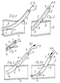
- 1 to 4 show a line 1 with an internal longitudinal cavity 2, for example a hose or a catheter, with regard to its anchoring in a blood vessel 3.
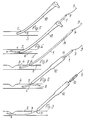
- Special application examples and configurations of this arrangement are in two embodiments, namely an embodiment according to 5 to 9 and a further embodiment according to Fig. 10 to 14 explained in more detail below.
- Matching parts receive matching reference numbers even with different designs.
- FIGS. 2, 7 and 8, and 11 and 12 It can be seen from FIGS. 2, 7 and 8, and 11 and 12 that a predetermined distance is provided between the mouth 4 of the line 1 and its entry 5 into the blood vessel 3. This is achieved in that the line 1 at this distance from its mouth 4 has a lateral perforation 6 or opening and that to fix the line 1 in the desired position a U-shaped thread 7 made of resilient material in the area of the mouth 4, it is therefore provided with a certain inherent rigidity which emerges through the lateral perforation 6 with a holding end 8.
- This thread 7 is held together by the area of the line 1 lying between the perforation 6 and the mouth 4 in its U-shaped or V-shaped position, so that the emerging holding end in the area of the perforation is first deflected against the direction in which a tensile load is applied could occur on line 1.
- the other end 9 of the thread protrudes from the area of line 1 located outside the blood vessel, so that according to.
- the thread 7 can first be displaced inward according to the arrow Pf2 to release it from its holding position until the holding end 8 has left the perforation 6 and expediently also the mouth 4 of the line 1; then the line 1 can be withdrawn and the thread 7 can still be used as a guide or the thread 7 can be withdrawn.
- FIG. 7 shows a known cutlery 10 through which according to. 6 the line 1, which is designed as a catheter in this case, is inserted with the thread loop.
- the line 1 or the catheter according to FIG. 7 gets stuck in the blood vessel 3 because the holding end 8 of the thread 7 lies against the inside of the blood vessel 3.
- the catheter or line 1 has a length marking 11. If such a marking 11 is not present from the outset, it could also be applied by the surgeon in the area which, in the position of use, lies approximately at the passage of the line 1 through the skin surface.
- This length marking 11 allows acc. 8 the pushing on of an insertion sleeve 12 until its mouth is shortly before the entry 5 into the blood vessel 3.
- a closure plug 13 can be guided over the thread 7 still protruding into the blood vessel 3 and somewhat inserted therein or an additional wire that can be inserted through the line 7 until it enters the blood vessel 3.
- the puncture opening serving as entry 5 for example an artery, can be securely closed, as is also shown in FIG. 14.
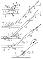
- a line 1 or a catheter with a seal of the entry area with respect to the entry 5 into the blood vessel 3 is shown.
- the line 1 is in turn inserted into the blood vessel 3 with a guide set 10.
- a detachable or removable balloon catheter 15a In the interior of the line 1 there is a detachable or removable balloon catheter 15a, the balloon 15 of which at least partially emerges from the mouth 4 located in the hollow organ or the blood vessel 3 in the position of use.
- the balloon 15 can, according to FIG. 11 are unfolded upstream and thus prevent the blood supply to the inlet 5 until a collagen closure 13 is arranged there.
- the insertion of the collagen plug 13 corresponds to Fig. 13 the mode of operation already shown in Fig. 9.
- a length marking 11 can also be 11 may be present.
- Fig.12 it is shown that the balloon 15 can also be unfolded immediately below the inlet 5 and at the mouth 4 of the line 1 in order to produce a temporary seal at this point until the collagen closure 13 after being pushed over the balloon catheter in accordance with .
- Fig. 14 has reached its position of use. After deflating the balloon 15, it can then be gem. the arrow Pf 3 in Fig. 14 are withdrawn through the tube-shaped collagen closure 13, after which the collagen automatically becomes a sealing closure in a known manner.
- the thread 7 is curved in a U-shape in the region of the mouth 4, that is to say in the insertion direction behind the perforation 6 or in the region between this perforation 6 and the mouth 4, and exits with a holding end 8 through the lateral perforation 6.
- the area of the line 1 lying between the perforation 6 and the mouth 4 is held together in its U-shaped or V-shaped position, the actual curvature possibly even being in front of or outside the mouth 4.
- the other end 9 of the thread 7 opposite the holding end 8 protrudes from the area of the line 1 located outside the hollow organ, so that to release the anchoring at this end 9 it can be pulled until the U-shaped or V-shaped loop is released and the holding end 8 are withdrawn.
- the thread can also lie twice and be bent over at its holding end 8, so that two loop-shaped layers result in the mouth region.
Landscapes
- Health & Medical Sciences (AREA)
- Life Sciences & Earth Sciences (AREA)
- Biophysics (AREA)
- Pulmonology (AREA)
- Engineering & Computer Science (AREA)
- Anesthesiology (AREA)
- Biomedical Technology (AREA)
- Heart & Thoracic Surgery (AREA)
- Hematology (AREA)
- Animal Behavior & Ethology (AREA)
- General Health & Medical Sciences (AREA)
- Public Health (AREA)
- Veterinary Medicine (AREA)
- Media Introduction/Drainage Providing Device (AREA)
Applications Claiming Priority (2)
| Application Number | Priority Date | Filing Date | Title |
|---|---|---|---|
| DE4218144 | 1992-06-02 | ||
| DE19924218144 DE4218144C1 (de) | 1992-06-02 | 1992-06-02 | Leitung zum Einführen in ein Hohlorgan |
Publications (1)
| Publication Number | Publication Date |
|---|---|
| EP0572934A1 true EP0572934A1 (fr) | 1993-12-08 |
Family
ID=6460210
Family Applications (1)
| Application Number | Title | Priority Date | Filing Date |
|---|---|---|---|
| EP93108640A Withdrawn EP0572934A1 (fr) | 1992-06-02 | 1993-05-28 | Conduite pour introduire dans une cavité d'un organe |
Country Status (3)
| Country | Link |
|---|---|
| EP (1) | EP0572934A1 (fr) |
| JP (1) | JPH06197973A (fr) |
| DE (1) | DE4218144C1 (fr) |
Families Citing this family (2)
| Publication number | Priority date | Publication date | Assignee | Title |
|---|---|---|---|---|
| DE19936120C2 (de) * | 1999-07-31 | 2001-07-05 | Jostra Ag | Vorrichtung zum Anschluss von medizinischen Sonden oder Kanülen |
| DE10108814A1 (de) * | 2001-02-16 | 2002-09-05 | Berlin Heart Ag | Vorrichtung zur Verbindung eines Hohlorgans mit einer Kanüle |
Citations (3)
| Publication number | Priority date | Publication date | Assignee | Title |
|---|---|---|---|---|
| US3924633A (en) * | 1974-01-31 | 1975-12-09 | Cook Inc | Apparatus and method for suprapubic catheterization |
| FR2652267A1 (fr) * | 1989-09-27 | 1991-03-29 | Prothia Sarl | Dispositif de catheter et filtre pour veine cave. |
| US5071407A (en) * | 1990-04-12 | 1991-12-10 | Schneider (U.S.A.) Inc. | Radially expandable fixation member |
Family Cites Families (1)
| Publication number | Priority date | Publication date | Assignee | Title |
|---|---|---|---|---|
| US3777761A (en) * | 1972-07-18 | 1973-12-11 | D Sheridan | Post operative drainage tubes with suture strip and method of use |
-
1992
- 1992-06-02 DE DE19924218144 patent/DE4218144C1/de not_active Expired - Fee Related
-
1993
- 1993-05-28 EP EP93108640A patent/EP0572934A1/fr not_active Withdrawn
- 1993-06-01 JP JP5130238A patent/JPH06197973A/ja active Pending
Patent Citations (3)
| Publication number | Priority date | Publication date | Assignee | Title |
|---|---|---|---|---|
| US3924633A (en) * | 1974-01-31 | 1975-12-09 | Cook Inc | Apparatus and method for suprapubic catheterization |
| FR2652267A1 (fr) * | 1989-09-27 | 1991-03-29 | Prothia Sarl | Dispositif de catheter et filtre pour veine cave. |
| US5071407A (en) * | 1990-04-12 | 1991-12-10 | Schneider (U.S.A.) Inc. | Radially expandable fixation member |
Also Published As
| Publication number | Publication date |
|---|---|
| JPH06197973A (ja) | 1994-07-19 |
| DE4218144C1 (de) | 1993-12-09 |
Similar Documents
| Publication | Publication Date | Title |
|---|---|---|
| DE69330119T2 (de) | Vorrichtung zum austauschen eines führungsdrahtes | |
| DE60310949T2 (de) | Drainagekatheter | |
| DE69212387T2 (de) | Intravenöse Vorrichtung | |
| DE68918632T2 (de) | Führungsdrahtverlängerung mit selbstverriegelbarer, lösbarer Verbindung. | |
| DE69709256T2 (de) | Expandierbare Diagnosekathetereinrichtung sowie Verfahren zur Herstellung derselben | |
| DE69219883T2 (de) | Vorrichtung zum austauschen eines kardiovaskulären führungskatheters unter zurückhalten eines zuvor eingesetzten angioplastie-führungsdrahte | |
| DE69116351T2 (de) | Vorrichtung zum zeitlichen Einsetzen eines Blutfilters in eine Vene des menschlichen Körpers | |
| DE60108014T2 (de) | Schnell austauschbarer katheter mit einer lösbaren haube | |
| DE60311414T2 (de) | Katheter mit geformter rampe für führungsdraht | |
| EP0999806B1 (fr) | Dispositif d'implantation intraluminal | |
| DE69827230T2 (de) | System zum anbringen eines drainagekatheters | |
| DE69734672T2 (de) | Gallenkatheter zum auswechseln durch einen einzelnen bediener | |
| DE69125476T2 (de) | Katheter mit foramenartiger verankerung | |
| DE69833882T2 (de) | Medizinischer transplantatverbinder oder stopfen sowie verfahren zu ihrer herstellung | |
| EP0256546B1 (fr) | Dispositif pour placer un tube d'alimentation dans l'estomac d'un homme ou d'un animal | |
| DE69921622T2 (de) | Konvertierbarer katheter mit einem kollabierbaren lumen | |
| DE69721577T2 (de) | Instrument zum geführten Abgeben von injektierbaren Materialien bei der Behandlung von Urininkontinenz | |
| DE3539439A1 (de) | Harnleiterkatheter | |
| DE19543713A1 (de) | Verbessertes verriegelbares Kathetersystem | |
| DE2005167B2 (de) | Postoperative Drain-Röhre | |
| DE8801645U1 (de) | Freihalte-Katheter | |
| DE10245076A1 (de) | Instrumentarium und Verfahren zur operativen Behandlung der Harninkontinenz der Frau | |
| EP3400914A1 (fr) | Poignée pour un cathéter et cathéter correspondant | |
| DE69726315T2 (de) | Katheter | |
| CH700478A1 (de) | Katheter. |
Legal Events
| Date | Code | Title | Description |
|---|---|---|---|
| PUAI | Public reference made under article 153(3) epc to a published international application that has entered the european phase |
Free format text: ORIGINAL CODE: 0009012 |
|
| 17P | Request for examination filed |
Effective date: 19930528 |
|
| AK | Designated contracting states |
Kind code of ref document: A1 Designated state(s): AT BE CH DE FR GB IE IT LI NL SE |
|
| 17Q | First examination report despatched |
Effective date: 19950802 |
|
| STAA | Information on the status of an ep patent application or granted ep patent |
Free format text: STATUS: THE APPLICATION IS DEEMED TO BE WITHDRAWN |
|
| 18D | Application deemed to be withdrawn |
Effective date: 19951201 |