EP0572976A1 - Winkelgeschwindigkeitsmessaufnehmer und damit ausgerüstete Kamera - Google Patents
Winkelgeschwindigkeitsmessaufnehmer und damit ausgerüstete Kamera Download PDFInfo
- Publication number
- EP0572976A1 EP0572976A1 EP93108798A EP93108798A EP0572976A1 EP 0572976 A1 EP0572976 A1 EP 0572976A1 EP 93108798 A EP93108798 A EP 93108798A EP 93108798 A EP93108798 A EP 93108798A EP 0572976 A1 EP0572976 A1 EP 0572976A1
- Authority
- EP
- European Patent Office
- Prior art keywords
- detection
- substrate
- angular velocity
- detecting
- portions
- Prior art date
- Legal status (The legal status is an assumption and is not a legal conclusion. Google has not performed a legal analysis and makes no representation as to the accuracy of the status listed.)
- Granted
Links
- 239000000758 substrate Substances 0.000 claims abstract description 82
- 238000001514 detection method Methods 0.000 claims description 165
- 238000012545 processing Methods 0.000 claims description 33
- 238000005530 etching Methods 0.000 claims description 26
- 230000001360 synchronised effect Effects 0.000 claims description 11
- 238000012937 correction Methods 0.000 claims description 9
- 230000003287 optical effect Effects 0.000 claims description 9
- 238000006073 displacement reaction Methods 0.000 claims description 6
- 230000010354 integration Effects 0.000 claims description 6
- 239000006089 photosensitive glass Substances 0.000 claims description 3
- 238000000034 method Methods 0.000 description 22
- HFGPZNIAWCZYJU-UHFFFAOYSA-N lead zirconate titanate Chemical compound [O-2].[O-2].[O-2].[O-2].[O-2].[Ti+4].[Zr+4].[Pb+2] HFGPZNIAWCZYJU-UHFFFAOYSA-N 0.000 description 16
- 229910052451 lead zirconate titanate Inorganic materials 0.000 description 16
- XUIMIQQOPSSXEZ-UHFFFAOYSA-N Silicon Chemical compound [Si] XUIMIQQOPSSXEZ-UHFFFAOYSA-N 0.000 description 13
- 239000011521 glass Substances 0.000 description 13
- 229910052710 silicon Inorganic materials 0.000 description 12
- 239000010703 silicon Substances 0.000 description 12
- 230000005284 excitation Effects 0.000 description 9
- 230000004048 modification Effects 0.000 description 8
- 238000012986 modification Methods 0.000 description 8
- 229910052581 Si3N4 Inorganic materials 0.000 description 7
- HQVNEWCFYHHQES-UHFFFAOYSA-N silicon nitride Chemical compound N12[Si]34N5[Si]62N3[Si]51N64 HQVNEWCFYHHQES-UHFFFAOYSA-N 0.000 description 7
- KRHYYFGTRYWZRS-UHFFFAOYSA-N Fluorane Chemical compound F KRHYYFGTRYWZRS-UHFFFAOYSA-N 0.000 description 6
- 238000004519 manufacturing process Methods 0.000 description 6
- 230000007246 mechanism Effects 0.000 description 6
- 238000000206 photolithography Methods 0.000 description 6
- 238000010586 diagram Methods 0.000 description 5
- 239000004809 Teflon Substances 0.000 description 4
- 229920006362 Teflon® Polymers 0.000 description 4
- XLOMVQKBTHCTTD-UHFFFAOYSA-N Zinc monoxide Chemical compound [Zn]=O XLOMVQKBTHCTTD-UHFFFAOYSA-N 0.000 description 4
- 239000013078 crystal Substances 0.000 description 4
- 230000035945 sensitivity Effects 0.000 description 4
- QGZKDVFQNNGYKY-UHFFFAOYSA-N Ammonia Chemical compound N QGZKDVFQNNGYKY-UHFFFAOYSA-N 0.000 description 3
- KWYUFKZDYYNOTN-UHFFFAOYSA-M Potassium hydroxide Chemical compound [OH-].[K+] KWYUFKZDYYNOTN-UHFFFAOYSA-M 0.000 description 3
- 238000013461 design Methods 0.000 description 3
- 230000000694 effects Effects 0.000 description 3
- 229910021421 monocrystalline silicon Inorganic materials 0.000 description 3
- 230000007935 neutral effect Effects 0.000 description 3
- 238000001020 plasma etching Methods 0.000 description 3
- RZVAJINKPMORJF-UHFFFAOYSA-N Acetaminophen Chemical compound CC(=O)NC1=CC=C(O)C=C1 RZVAJINKPMORJF-UHFFFAOYSA-N 0.000 description 2
- OKTJSMMVPCPJKN-UHFFFAOYSA-N Carbon Chemical compound [C] OKTJSMMVPCPJKN-UHFFFAOYSA-N 0.000 description 2
- 239000004593 Epoxy Substances 0.000 description 2
- OAKJQQAXSVQMHS-UHFFFAOYSA-N Hydrazine Chemical compound NN OAKJQQAXSVQMHS-UHFFFAOYSA-N 0.000 description 2
- BQCADISMDOOEFD-UHFFFAOYSA-N Silver Chemical compound [Ag] BQCADISMDOOEFD-UHFFFAOYSA-N 0.000 description 2
- 239000000853 adhesive Substances 0.000 description 2
- 230000001070 adhesive effect Effects 0.000 description 2
- 230000015572 biosynthetic process Effects 0.000 description 2
- 229910052799 carbon Inorganic materials 0.000 description 2
- PCHJSUWPFVWCPO-UHFFFAOYSA-N gold Chemical compound [Au] PCHJSUWPFVWCPO-UHFFFAOYSA-N 0.000 description 2
- 229910052737 gold Inorganic materials 0.000 description 2
- 239000010931 gold Substances 0.000 description 2
- 239000000463 material Substances 0.000 description 2
- 239000005297 pyrex Substances 0.000 description 2
- 229910052709 silver Inorganic materials 0.000 description 2
- 239000004332 silver Substances 0.000 description 2
- 230000001629 suppression Effects 0.000 description 2
- TXEYQDLBPFQVAA-UHFFFAOYSA-N tetrafluoromethane Chemical compound FC(F)(F)F TXEYQDLBPFQVAA-UHFFFAOYSA-N 0.000 description 2
- 239000011787 zinc oxide Substances 0.000 description 2
- KXSKAZFMTGADIV-UHFFFAOYSA-N 2-[3-(2-hydroxyethoxy)propoxy]ethanol Chemical compound OCCOCCCOCCO KXSKAZFMTGADIV-UHFFFAOYSA-N 0.000 description 1
- VYZAMTAEIAYCRO-UHFFFAOYSA-N Chromium Chemical compound [Cr] VYZAMTAEIAYCRO-UHFFFAOYSA-N 0.000 description 1
- 101000693243 Homo sapiens Paternally-expressed gene 3 protein Proteins 0.000 description 1
- 241000511976 Hoya Species 0.000 description 1
- 102100025757 Paternally-expressed gene 3 protein Human genes 0.000 description 1
- XAGFODPZIPBFFR-UHFFFAOYSA-N aluminium Chemical compound [Al] XAGFODPZIPBFFR-UHFFFAOYSA-N 0.000 description 1
- 229910052782 aluminium Inorganic materials 0.000 description 1
- 229910021529 ammonia Inorganic materials 0.000 description 1
- 230000008859 change Effects 0.000 description 1
- 238000006243 chemical reaction Methods 0.000 description 1
- 229910052804 chromium Inorganic materials 0.000 description 1
- 239000011651 chromium Substances 0.000 description 1
- 239000011248 coating agent Substances 0.000 description 1
- 238000000576 coating method Methods 0.000 description 1
- 230000003247 decreasing effect Effects 0.000 description 1
- 238000000151 deposition Methods 0.000 description 1
- MROCJMGDEKINLD-UHFFFAOYSA-N dichlorosilane Chemical compound Cl[SiH2]Cl MROCJMGDEKINLD-UHFFFAOYSA-N 0.000 description 1
- 238000001914 filtration Methods 0.000 description 1
- 230000005484 gravity Effects 0.000 description 1
- 238000010438 heat treatment Methods 0.000 description 1
- 238000005468 ion implantation Methods 0.000 description 1
- 230000033001 locomotion Effects 0.000 description 1
- 238000004518 low pressure chemical vapour deposition Methods 0.000 description 1
- 239000000203 mixture Substances 0.000 description 1
- 238000012544 monitoring process Methods 0.000 description 1
- 229920002120 photoresistant polymer Polymers 0.000 description 1
- 230000010287 polarization Effects 0.000 description 1
- 239000000843 powder Substances 0.000 description 1
- 230000008569 process Effects 0.000 description 1
- 239000010453 quartz Substances 0.000 description 1
- 230000009467 reduction Effects 0.000 description 1
- 238000007650 screen-printing Methods 0.000 description 1
- 238000007789 sealing Methods 0.000 description 1
- VYPSYNLAJGMNEJ-UHFFFAOYSA-N silicon dioxide Inorganic materials O=[Si]=O VYPSYNLAJGMNEJ-UHFFFAOYSA-N 0.000 description 1
- 238000004528 spin coating Methods 0.000 description 1
- 238000004544 sputter deposition Methods 0.000 description 1
- 230000006641 stabilisation Effects 0.000 description 1
- 238000011105 stabilization Methods 0.000 description 1
- WGTYBPLFGIVFAS-UHFFFAOYSA-M tetramethylammonium hydroxide Chemical compound [OH-].C[N+](C)(C)C WGTYBPLFGIVFAS-UHFFFAOYSA-M 0.000 description 1
Images


Classifications
-
- G—PHYSICS
- G01—MEASURING; TESTING
- G01C—MEASURING DISTANCES, LEVELS OR BEARINGS; SURVEYING; NAVIGATION; GYROSCOPIC INSTRUMENTS; PHOTOGRAMMETRY OR VIDEOGRAMMETRY
- G01C19/00—Gyroscopes; Turn-sensitive devices using vibrating masses; Turn-sensitive devices without moving masses; Measuring angular rate using gyroscopic effects
- G01C19/56—Turn-sensitive devices using vibrating masses, e.g. vibratory angular rate sensors based on Coriolis forces
- G01C19/5719—Turn-sensitive devices using vibrating masses, e.g. vibratory angular rate sensors based on Coriolis forces using planar vibrating masses driven in a translation vibration along an axis
-
- H—ELECTRICITY
- H04—ELECTRIC COMMUNICATION TECHNIQUE
- H04N—PICTORIAL COMMUNICATION, e.g. TELEVISION
- H04N23/00—Cameras or camera modules comprising electronic image sensors; Control thereof
- H04N23/60—Control of cameras or camera modules
- H04N23/68—Control of cameras or camera modules for stable pick-up of the scene, e.g. compensating for camera body vibrations
- H04N23/681—Motion detection
- H04N23/6812—Motion detection based on additional sensors, e.g. acceleration sensors
-
- H—ELECTRICITY
- H04—ELECTRIC COMMUNICATION TECHNIQUE
- H04N—PICTORIAL COMMUNICATION, e.g. TELEVISION
- H04N23/00—Cameras or camera modules comprising electronic image sensors; Control thereof
- H04N23/60—Control of cameras or camera modules
- H04N23/68—Control of cameras or camera modules for stable pick-up of the scene, e.g. compensating for camera body vibrations
- H04N23/682—Vibration or motion blur correction
- H04N23/685—Vibration or motion blur correction performed by mechanical compensation
- H04N23/687—Vibration or motion blur correction performed by mechanical compensation by shifting the lens or sensor position
Definitions
- the present invention relates to an angular velocity sensor capable of simultaneously detecting angular velocities about multiple axes and a camera including the same.
- a gyro As a conventional means for detecting the angular velocity of an object, a gyro is known. As is well known, the gyro comprises a mechanical mechanism utilizing the principle of a top. The gyro comprising the mechanical mechanism can detect an angular velocity with high precision, but requires high-precision parts and, hence, is very expensive since it has a quasi-mechanical structure. In addition, the gyro undesirably has a large volume and weight. For this reason, although demand for high-precision detection of an angular velocity using the gyro has increased, when the conventional mechanical gyro is equipped in various apparatuses or devices, the apparatuses or devices undesirably become large and heavy. For this reason, the conventional mechanical gyro is utilized in only a relatively limited field.
- the above-mentioned vibration gyro detects an angular velocity by detecting a Coriolis' force generated in a vibrating member when the angular velocity caused by an external force is applied to the vibrating member such as a tuning fork which vibrates at a constant frequency. Since the vibration gyro does not require a rotary top, it is compact, can be manufactured with low cost, and allows high-precision detection. For this reason, it is expected that the vibration gyro is utilized in various devices.
- the vibration gyro shown in Fig. 1 includes fixed vibration pieces 1101 and 1102, driving piezoelectric elements 1103 and 1104, respectively attached to the vibration pieces 1101 and 1102, for vibrating stationary members 1112 and 1113 in the X-direction in Fig.
- monitor piezoelectric elements 1105 and 1106 for monitoring actual vibrations of the vibration pieces 1101 and 1102, which are vibrated by the driving piezoelectric elements 1103 and 1104, detection vibration pieces 1109 and 1110 respectively attached to the stationary members 1112 and 1113, and detection piezoelectric elements 1107 and 1108, respectively attached to the detection vibration pieces 1109 and 1110, for detecting angular velocities.
- piezoelectric elements 1103, 1104, 1105, 1106, 1107, and 1108 correspond to the driving piezoelectric elements 1103 and 1104, the monitor piezoelectric elements 1105 and 1106, and the detection piezoelectric elements 1107 and 1108 shown in Fig. 1.
- a circuit shown in Fig. 2 includes amplifiers 1201, 1207, and 1209. The amplifier 1201 amplifies signals from the monitor piezoelectric elements 1105 and 1106, the amplifier 1207 supplies a driving signal to the driving piezoelectric elements 1103 and 1104, and the amplifier 1209 amplifies angular velocity detection signals from the detection piezoelectric elements 1107 and 1108.
- a phase shifting circuit 1202 shifts the phase of a monitor output amplified by the amplifier 1201.
- a rectification circuit 1203 rectifies a signal from the amplifier 1201, and generates a rectified voltage.
- a reference voltage generating circuit 1204 generates a reference voltage for suppressing an input voltage to the driving piezoelectric elements 1103 and 1104 so as to make constant the amplified voltage from the amplifier 1201.
- a differential amplifier 1205 generates an output obtained by amplifying a difference between the output voltage from the rectification circuit 1203 and the reference voltage from the reference voltage generating circuit 1204.
- a multiplication circuit 1206 multiplies the output voltage from the phase shifting circuit 1202 with the output voltage from the differential amplifier 1205, and applies the product to the driving piezoelectric elements 1103 and 1104 via the amplifier 1207.
- a band-pass filter 1210 allows frequency band components corresponding to the resonance frequency ⁇ 1 of the vibration pieces 1101 and 1102 of the output signals from the detection piezoelectric elements 1107 and 1108, which signals are amplified by the amplifier 1209, to pass therethrough.
- the output signal from the band-pass filter 1210 is synchronously detected by a synchronous detection circuit 1211 on the basis of the output signal from a phase shifting circuit 1208, thus generating a synchronously detected voltage.
- a low-pass filter 1212 allows a specific low-frequency component of the output from the synchronous detection circuit 1211 to pass therethrough.
- An output amplifier 1213 amplifies the output from the low-pass filter 1212, and generates an output representing the angular velocity ⁇ .
- the vibration pieces 1101 and 1102 when the vibration pieces 1101 and 1102 are excited by the driving piezoelectric elements 1103 and 1104 attached thereto, they vibrate in the X-direction, and resonate with each other. Therefore, the detection vibration pieces 1109 and 1110 attached to the vibration pieces 1101 and 1102 similarly vibrate.
- the monitor piezoelectric elements 1105 and 1106 respectively amplify monitor voltages proportional to the amplitudes of the vibrations in the X-direction of the vibration pieces 1101 and 1102 and the detection vibration pieces 1109 and 1110.
- the phase shifting circuit 1202 generates an output voltage obtained by phase-shifting the output voltage from the amplifier 1201 through 90°.
- the rectification circuit 1203 generates a positive voltage obtained by rectifying the output voltage from the amplifier 1201. Therefore, the differential amplifier 1205 generates an output obtained by amplifying a difference between the output voltage from the rectification circuit 1203 and the reference voltage from the reference voltage generating circuit 1204, and supplies this output to the multiplication circuit 1206.
- the multiplication circuit 1206 fetches the output from the phase shifting circuit 1202 (i.e., a signal obtained by phase-shifting the outputs from the monitor piezoelectric elements 1105 and 1106 through 90°) and the output from the differential amplifier 1205, and generates an output equal to a product of the fetched outputs.
- the amplifier 1207 amplifies the output from the multiplication circuit 1206.
- the outputs from the monitor piezoelectric elements 1105 and 1106 are fed back to the driving piezoelectric elements 1103 and 1104 via the multiplication circuit 1206, and the driving piezoelectric elements 1103 and 1104 are controlled by the multiplication circuit 1206 to be always driven at a constant voltage.
- the detection vibration pieces 1101 and 1102 are displaced by the Coriolis forces Fc in the Y-direction in proportion to the angular velocity ⁇ . Therefore, the detection piezoelectric elements 1107 and 1108 respectively generate outputs proportional to the products of the vibration velocities v of the vibration pieces and the angular velocity ⁇ , and these outputs are amplified by the amplifier 1209. Thereafter, the amplified outputs are input to the band-pass filter 1210.
- the outputs from the detection piezoelectric elements 1107 and 1108 are amplitude-modulated waves obtained by amplitude-modulating the resonance frequency ⁇ 1 of the vibration pieces 1101 and 1102 with the angular velocity ⁇ , and the pass band of the band-pass filter 1210 is set at the resonance frequency ⁇ 1.
- the output from the band-pass filter 1210 corresponds to one obtained by filtering out the vibration components at the resonance frequency ⁇ 1 from the outputs from the detection piezoelectric elements 1107 and 1108.
- the output from the band-pass filter 1210 is synchronously detected by the synchronous detection circuit 1211 on the basis of the output from the phase shifting circuit 1208.
- the output from the phase shifting circuit 1208 is obtained by phase-shifting the outputs from the monitor piezoelectric elements 1105 and 1106 through 90°, and hence, the output from the synchronous detection circuit 1211 is proportion to ⁇ .
- the output from the synchronous detection circuit 1211 is input to the low-pass filter 1212.
- the low-pass filter 1212 removes high-frequency components from the input. Then, the output from the low-pass filter 1212 is input to the output amplifier 1213.
- the output amplifier 1213 amplifies the output from the low-pass filter 1212 to a proper amplitude, and outputs the amplified signal. This output signal is supplied to, e.g., a display.
- the vibration gyro is smaller and requires lower cost than a gyro comprising a mechanical mechanism utilizing the principle of a top.
- the size and cost of the vibration gyro are not sufficiently small for a compact device.
- one angular velocity sensor is required for one detection axis, and angular velocity sensors and a mounting space corresponding to detection axes are required. For this reason, when the conventional angular velocity sensors are used in a system requiring multi-axis detection, it is difficult to make the system compact.
- the present invention has been made to solve the conventional problems, and has as its object to provide a compact, low-cost angular velocity sensor capable of simultaneously detecting angular velocities about multiple axes, and a camera including the same.
- an angular velocity sensor comprises: a flat substrate having a flat surface; a movable portion which is provided to a portion of the substrate and can be vibrated in a direction perpendicular to the surface; a first weight portion provided to one portion of the movable portion; a first beam portion, extending in a first direction parallel to the surface, for supporting the first weight portion; a second weight portion provided to another portion of the movable portion; a second beam portion, extending in a second direction parallel to the surface and different from the first direction, for supporting the second weight portion; driving means for vibrating the movable portion in a direction perpendicular to the surface; detection means for detecting deformations of the first and second beam portions generated upon reception of Coriolis' forces when the substrate is rotated about the first and second directions as rotational axes; and a signal processing circuit for detecting angular velocities of rotations about the first and second directions as the rotational axes on the basis of the deformations of the first
- another angular velocity sensor comprises: a flat first substrate having a flat surface; a first movable portion which is provided to a portion of the first substrate and can be vibrated in a direction perpendicular to the surface; a first weight portion provided to one portion of the first movable portion; a first beam portion, extending in a first direction parallel to the surface, for supporting the first weight portion; a second weight portion provided to another portion of the first movable portion; a second beam portion, extending in a second direction parallel to the surface and different from the first direction, for supporting the second weight portion; a flat second substrate arranged parallel to the first substrate and having a flat surface; a second movable portion which is provided to a portion of the second substrate and can be vibrated in a direction perpendicular to the surface; a third weight portion provided to one portion of the second movable portion; a third beam portion, extending in the first direction, for supporting the third weight portion; a fourth weight portion provided to another portion of the second
- a camera comprises: a lens for forming an image on an image surface; an angular velocity sensor, attached to the camera, for outputting a detection signal; an integration circuit for outputting an angular displacement signal by integrating the output signal from the angular velocity sensor; and a correction optical system for correcting a blur of the image formed on the image surface in accordance with the angular displacement signal output from the integration circuit
- the angular velocity sensor comprising: a flat substrate having a flat surface; a movable portion which is provided to a portion of the substrate and can be vibrated in a direction perpendicular to the surface; a first weight portion provided to one portion of the movable portion; a first beam portion, extending in a first direction parallel to the surface, for supporting the first weight portion; a second weight portion provided to another portion of the movable portion; a second beam portion, extending in a second direction parallel to the surface and different from the first direction, for supporting the second weight portion; driving means for vibrating the a flat substrate having a
- an angular velocity sensor is manufactured by working a flat plate, a sensor having a small thickness can be realized.
- a flat plate material of the present invention materials such as single-crystal silicon, quartz, photosensitive glass, and the like, which can be etched using a photolithography method, can be used. Since the photolithography method allows application of an etching processing having high precision, a shape having high dimensional precision can be worked, and as a result, an angular velocity sensor having high sensitivity can be provided.
- a driving source having a high driving source such as a piezoelectric element using sintered PZT (lead zirconate titanate) can be used. Since a common driving unit is used, the size of the driving unit can be increased relative to the size of each sensor, and excitation of vibration with high controllability is allowed even in a compact sensor by a reduction in working error with respect to the size and by a large driving force.
- a high driving source such as a piezoelectric element using sintered PZT (lead zirconate titanate)
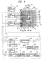
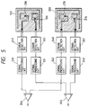
- Figs. 3 to 5 show an angular velocity sensor according to the first embodiment of the present invention. More specifically, Fig. 3 is a schematic perspective view and a diagram of the angular velocity sensor, Fig. 4 is an enlarged view of a detection portion, and Fig. 5 is a schematic diagram showing a signal processing circuit.
- a sensor comprises a flat single-crystal silicon substrate 101. By removing a portion of this substrate to form gaps 105, a movable portion 102, weight portions 103 and 203, and detection beam portions 104 and 204 are formed.
- the movable portion 102 has a cantilever beam structure.
- the substrate 101 has a smaller thickness than other portions at a beam root portion 107 of the movable portion 102, and the movable portion 102 is formed to be able to be vibrated in the direction of an arrow A perpendicular to the surface of the substrate.
- the movable portion 102 is vibrated by an excitation PZT piezoelectric element 108 as a driving source in the direction of the arrow A with respect to a base portion 112 of the substrate.
- the vibration of the movable portion 102 is detected by excitation detection PZT piezoelectric elements 109a and 109b.
- the weight portion 103 and the beam portion 104 are formed in one portion of the movable portion 102.
- the beam portion 104 has a shape elongated in a direction parallel to a rotational axis 114 parallel to the substrate surface, and supports the weight portion 103 with respect to the movable portion 102.
- the weight portion 203 and the beam portion 204 are formed in another portion of the movable portion 102.
- the beam portion 204 has a shape elongated in a direction parallel to a rotational axis 113 parallel to the substrate surface and perpendicular to the rotational axis 114, and supports the weight portion 203 with respect to the movable portion 102. More specifically, the weight portion 203 and the beam portion 204 define a shape obtained by rotating the weight portion 103 and the beam portion 104 through 90°.
- the weight portion 103 and the beam portion 104 receive a Coriolis' force corresponding to the angular velocity of a rotation in the direction of an arrow 116, and the beam portion 104 deforms.
- the weight portion 203 and the beam portion 204 receive a Coriolis' force corresponding to the angular velocity of a rotation in the direction of an arrow 115, and the beam portion 204 deforms.
- the angular velocities about the rotational axes 114 and 113 are respectively detected.
- the deformation of the beam portion 104 is detected by a detection element 106 attached to the beam portion 104.
- the detection element 106 consists of a pair of piezo resistors 106a and 106b, as shown in the enlarged view of a detection portion in Fig. 4. These piezo resistors 106a and 106b are attached to be symmetrical about a central line 202 in the longitudinal direction of the beam portion. As described above, upon reception of the Coriolis' force, the beam portion 104 deforms to contract at one side of the central line 202 and to expand on the other side thereof. For this reason, upon deformation of the beam portion 104, the resistances of the piezo resistors 106a and 106b have a difference therebetween.
- a strain detection circuit 117 When this resistance difference is converted into a voltage signal by a strain detection circuit 117 shown in Fig. 3, the deformation of the beam portion 104 is detected.
- the output signal from the strain detection circuit 117 is input to a signal processing circuit 131, and the signal processing circuit 131 outputs a detection signal of the angular velocity of the rotation about the rotational axis 114.
- the detection element 106 and the strain detection circuit 117 are connected to each other via lead electrodes 110 and lead electrode lead portions 111.
- the deformation of the beam portion 204 is detected by a detection element 206 attached to the beam portion 204.
- the detection element 206 consists of a pair of piezo resistors as in the detection element 106, and is connected to a strain detection circuit 217.
- the strain detection circuit 217 detects the deformation of the beam portion 204 as in the strain detection circuit 117, and outputs a voltage signal.
- the output signal from the strain detection circuit 217 is input to a signal processing circuit 231 as in the signal processing circuit 131, and the signal processing circuit 231 outputs a detection signal of the angular velocity about the rotational axis 113.
- the output signal from the strain detection circuit 117 is amplified by an amplifier 126, and is input to a synchronous detection circuit 128 via a band-pass filter 127 which allows a frequency band component of a resonance frequency ⁇ 1 of the piezoelectric element 108 to pass therethrough.
- detection signals of the vibration of the movable portion 102 output from the excitation detection PZT piezoelectric elements 109a and 109b are amplified by an amplifier 118.
- the output from the amplifier 118 is phase-shifted by a phase shifting circuit 125, and the phase-shifted signal is input to the synchronous detection circuit 128.
- the synchronous detection circuit 128 synchronously detects the output signal from the filter 127 on the basis of the output signal from the phase shifting circuit 125, and outputs the detected signal as a synchronously detected voltage.
- the output from the synchronous detection circuit 128 is amplified by an output amplifier 130 via a low-pass filter 129 which allows a specific low-frequency component to pass therethrough, and is output as a detection signal of the angular velocity.
- the output voltage from the amplifier 118 is rectified by a rectification circuit 122, and a differential amplifier 123 outputs a voltage corresponding to a difference between the output signal from the rectification circuit 122 and a reference voltage generated by a reference voltage generating circuit 124.
- the output voltage from the differential amplifier 123 is multiplied with the output voltage from the amplifier 118, which is input to a multiplication circuit 120 via a phase shifting circuit 119, thereby controlling the output from the multiplication circuit 120 to be constant.
- the output from the multiplication circuit 120 is input to the excitation PZT piezoelectric element 108 via an amplifier 121, thus stably vibrating the movable portion 102.
- the movable portion 102 is vibrated in the direction of the arrow A by applying a constant AC voltage to the excitation PZT piezoelectric element 108.
- the outputs from the driving detection PZT piezoelectric elements 109a and 109b are detected, and the AC voltage to be applied to the excitation PZT piezoelectric element 108 is adjusted by a driving circuit including the amplifier 118, the phase shifting circuit 119, the multiplication circuit 120, the amplifier 121, the rectification circuit 122, the differential amplifier 123, and the reference voltage generating circuit 124, so that the driving frequency has a desired value, thereby obtaining a constant vibration.
- the strain detection circuit 117 detects a resistance difference (strain amount), caused by the deformation, of the pair of piezo resistors 106a and 106b formed at two sides of a neutral surface of the beam.
- the strain detection circuit 117 converts the detected resistance difference into a voltage signal, and outputs the voltage signal.
- the output signal from the strain detection circuit 117 is converted into a signal representing the angular velocity via the amplifier 126, the band-pass filter 127, the synchronous detection circuit 128, the low-pass filter 129, and the output amplifier 130, and the converted signal is output from the output amplifier 130.
- a detection signal of the angular velocity of the rotation about the rotational axis 113 is output from the signal processing circuit 231 via the strain detection circuit 217 on the basis of the output from the detection element 206.
- a substrate 200 having the same arrangement as that of the substrate 101 is additionally arranged to be parallel to the substrate 101.
- the movable portions of the substrates 101 and 200 are vibrated in opposite phases in the direction of the arrow A.
- the substrate 200 has a detection element 216 having the same arrangement as that of the detection element 106, and a signal processing circuit 243 having the same arrangement as that of the signal processing circuit 131 outputs a detection signal of the angular velocity via a strain detection circuit 241.
- the output from the signal processing circuit 243 becomes a signal obtained by inverting the phase of the output from the signal processing circuit 131. Therefore, when the outputs from these signal processing circuits 131 and 243 are differentiated by a differential amplifier 245, a detection signal of the angular velocity of the rotation about the rotational axis 114 can be obtained.
- an output signal from a detection element 226 having the same arrangement as that of the detection element 206 is input to a signal processing circuit 242 having the same arrangement as that of the signal processing circuit 231 via a strain detection circuit 240.
- a differential amplifier 244 differentiates the outputs from the signal processing circuits 242 and 231, thereby obtaining a detection signal of the angular velocity of the rotation about the rotational axis 113.
- the influence of a disturbance on the angular velocity sensor can be minimized, and angular velocities can be detected with higher precision.
- the differential amplifiers 244 and 245 may be arranged at any positions between the strain detection circuits and the signal processing circuits to obtain substantially the same effect as described above. Therefore, the differential amplifiers can be arranged at proper positions in consideration of the circuit scale, circuit characteristics, and the like.
- the driving frequency was set to be 15 kHz, and the input voltage was set to be ⁇ 5 V.
- the obtained outputs were detected in the above-mentioned arrangement, angular velocities could be satisfactorily detected in the two axial directions, and an output of 0.1 mV was obtained at an angular velocity of 1°/sec.
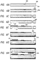
- the movable portion 102, the weight portions 103 and 203, and the beam portions 104 and 204 are integrally formed by anisotropically etching a 1-mm thick n-type single-crystal silicon substrate having a ⁇ 100 ⁇ direction. This manufacturing method will be described in detail below with reference to Figs. 6A to 6H.
- Figs. 6A to 6H illustrate a silicon substrate 301, a thermal oxide film 302, a piezo resistor portion 303, a silicon nitride film 304, an etching portion 305 for forming the beam portions 104 and 204, the weight portions 103 and 203, and the movable portion 102, a silicon (111) surface 306, an etching portion 307 for a driving portion, a vertical etching surface 308, a piezo resistor electrode 309, a driving electrode 310, a driving cantilever beam portion 311, a glass substrate 312, a groove portion 313 formed in the glass substrate, a PZT sintered body 314, and a Teflon sheet 315.
- a resist was patterned by a photolithography technique to form a piezo resistor pattern by removing a portion of the thermal oxide film 302 by etching. Then, a p-type piezo resistor 303 was formed using an ion-implantation method. At this time, the width of a beam portion on the upper surface of the movable portion was set to be 100 ⁇ m, and piezo resistor portions each having a 10- ⁇ m wide resistor line were formed at two sides of a neutral surface of each of the beam portions 104 and 204. As shown in Fig.
- a 0.2- ⁇ m thick silicon nitride film 304 was deposited on the two surfaces of the substrate by an LPCVD method using a mixture of dichloro silane and ammonia gas as a source gas. Then, the silicon nitride films on etching portions 305, on the two surfaces of the substrate, for forming the weight portions 103 and 203, the detection beam portions 104 and 204, and the movable portions 102 of the detection portions were removed by a photolithography method using a double-sided mask aligner device. The silicon nitride films were removed by a reactive ion etching method using carbon tetrafluoride.
- the substrate was etched for a required period of time in an aqueous potassium hydroxide solution heated to about 110°C, thus obtaining a state shown in Fig. 6C.
- a (111) crystal plane 306 of silicon appears depending on a difference in etching rate between crystal planes.
- a cantilever beam structure which allows the movable portion formed with the detection portions to be able to be driven in a direction perpendicular to the surface, is manufactured.
- etching was performed to adjust the thickness of the root portion 107 of the cantilever beam and to obtain a desired driving frequency.
- an etching portion 307 of the silicon nitride film was patterned, and etching was performed using the heated aqueous potassium hydroxide solution.
- a beam portion 311 is formed by this etching, and a desired sensor structural body can be formed by causing a time required for obtaining an almost vertical section upon etching of the weight portions 103 and 203, the beam portions 104 and 204, and the movable portion 102 to coincide with a time required for obtaining the desired thickness of the driving beam portion during etching.
- the aqueous potassium hydroxide solution was used as an etching solution.
- etching solutions such as hydrazine, ammonia, tetramethyl ammonium oxide, and the like, which anisotropically etch silicon, can be used.
- contact holes for electrical connections with the piezo resistor portions 303 were formed in the silicon nitride film 304 by the photolithography method and a reactive ion etching method using carbon tetrafluoride, and a resist pattern for an electrode was formed. Thereafter, aluminum electrodes were formed in a desired pattern using a deposition method and a lift-off method. The sensor was cut into a desired size from the silicon substrate, thus forming the base portion 112.
- the silicon nitride film on the rear surface of the base portion 112 was removed by a reactive ion etching method. Thereafter, a 1-mm thick pyrex glass plate (Corning Glass Works #7740) 312, in which a groove portion 313 having a depth of about 0.5 mm was formed in advance in a central portion by etching in a 50% hydrofluoric acid solution so as to leave a frame portion having a width of about 1 mm, was anodic-bonded to the base portion 112, thus attaining a state shown in Fig. 6F.
- the anodic bonding was performed at a temperature of 380°C while the base portion 112 side was set at a positive potential, the pyrex glass side was set at a negative potential, and a voltage of 400 V was applied for 10 minutes. Thereafter, an epoxy-based adhesive which was imparted conductivity by dispersing an Ag powder was coated on an excitation PZT piezoelectric element 314 and an excitation detection PZT piezoelectric element 109 each of which was formed with silver electrodes on two surfaces by coating a silver paste by a screen printing method, and was subjected to a polarization treatment.
- the outer dimensions of the base portion were 17 x 14 mm, and the thickness and length of each of the driving beam portion 311 and the PZT sintered body 314 were respectively 300 ⁇ m and 5 mm.
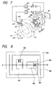
- Fig. 7 shows an image blur suppression system for a camera using the angular velocity sensor of this embodiment.
- the system illustrated in Fig. 7 includes a correction optical system 40, a center 41 of an optical axis, vertical and horizontal camera shake directions 41P and 41Y, a lens barrel 42, an angular velocity sensor 43 described in the above embodiment, integration circuits 45P and 45Y, a portion 46 of a stationary lens, correction optical system driving units 47P and 47Y, correction optical system position sensors 48P and 48Y, and an image surface 49.
- Two angular velocities in detection directions 44P and 44Y are detected by the angular velocity sensor 43, and signals from the angular velocity sensor are integrated by the integration circuits 45P and 45Y to be converted into camera shake angular displacements.
- the converted angular displacement signals are input to the driving units 47P and 47Y for displacing the correction optical system 40 in the X- and Y-directions to drive the correction optical system 40, thus assuring image stabilization on the image surface 49, and suppressing an image blur.
- correction position detection is performed using the position detection sensors 48P and 48Y of the correction optical system 40, and detection signals are utilized in feedback control.
- the image blur suppression system for the camera with the above-mentioned arrangement satisfactorily operated to suppress an image blur.
- the angular velocity sensor is arranged on the distal end portion of the lens barrel 42, but may be arranged at another position convenient for a camera design as long as the angular velocity detection directions 44P and 44Y coincide with the camera shake directions 41P and 41Y.
- the angular velocity sensor of this embodiment since the angular velocity sensor of this embodiment has a low-profile structure, it may be arranged behind the image surface 49 without forming a large bulge unlike a conventional angular velocity sensor. For this reason, limitations on an apparatus design can be decreased.
- the characteristics of the above-mentioned angular velocity sensor of this embodiment can be further improved.
- Fig. 6H when the two sensor portions are adhered to each other under reduced pressure, the interior of the sensor can be set in a reduced pressure state.
- the electro-mechanical conversion characteristics of a vibration can be improved, and sensitivity can be improved to about 10 to 100 times.
- the sensor output can be thermally stabilized.
- a glass substrate etched into a required pattern may be used in place of the Teflon sheet, and a voltage of about 400 V may be applied to the glass substrate and the silicon substrate while a carbon laser beam is radiated onto only portions to be adhered at normal temperature, and the silicon substrate side is set at a positive potential.
- adhesion was performed by radiating the carbon laser beam from the substrate end face side.
- circuit components described in this embodiment may adopt a CMOS arrangement to form a circuit in the silicon substrate on which the sensor is formed.
- the circuit arrangement can be rendered compact, the system using the sensor can be rendered further compact.
- Figs. 8 to 12 are views for explaining the second embodiment of the present invention.
- Fig. 8 is a plan view of a sensor
- Figs. 9A to 9E are sectional views showing manufacturing processes, taken along a line A - A' of an angular velocity sensor shown in Fig. 8
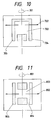
- Figs. 10 and 11 are plan views showing modifications of a detection portion of the angular velocity sensor
- Fig. 12 is a plan view for explaining the angular velocity sensor adopting another modification.
- Fig. 8 and Figs. 9A to 9E illustrate a glass substrate 501, a driving hinge beam portion 502, a gap portion 503, a weight portion 504, a detection beam portion 505, a detection piezoelectric element 506, a movable portion 507 formed with a detection portion, an etching mask portion 601, an ultraviolet exposure mask 602, a driving piezoelectric element 603, sealing silicon substrates 604 and 606, and a sensor gap portion 605.
- an angular velocity is detected by detecting, on the basis of a difference between outputs from a pair of detection piezoelectric elements 506 formed at two sides of a neutral surface of flexure of the beam portion, a strain amount generated when the weight portion 504 and the detection beam portion 505 receive a Coriolis' force, and the beam portion 505 is subjected to flexural deformation in the planar direction.
- the movable portion 507 formed with a detection portion is vibrated in a direction substantially perpendicular to the substrate surface by a driving mechanism constituted by a pair of hinge beam portions 502.
- a PZT sintered body as a piezoelectric element is used as a piezoelectric element.
- a glass substrate 501 1-mm thick PEG3 photosensitive glass (available from HOYA CORP.) was used as a glass substrate 501.
- a photoresist layer was formed on the surface of the glass substrate 501 by a spin coating method, and was patterned into a pattern for forming a hinge beam portion 502, thus forming an etching mask portion 601. Thereafter, etching was performed using a special-purpose Teflon jig (not shown), which allowed only one surface of the substrate to contact a 50% hydrofluoric acid solution, so that the hinge beam portion 502 had a required thickness. In this embodiment, the thickness of about 0.4 ⁇ m was left by controlling the etching time.
- an ultraviolet mask portion 602 which was formed into a pattern of a gap portion 503 (Fig. 8) was formed on a surface opposite to the etched surface of the substrate.
- Ultraviolet rays were radiated, and after the mask portion was removed, the radiated portion was developed by a heat treatment. Then, ultraviolet rays were further radiated to expose a non-exposed portion. Thereafter, etching was performed using a 10% hydrofluoric acid solution, thereby forming the gap portion 503.
- Gold electrodes having chromium base electrodes for detection electrodes (not shown), a zinc oxide film and gold electrodes (not shown) on the zinc oxide film for the detection piezoelectric elements 506, and detection portion lead electrodes (not shown) were formed into a required pattern using a sputtering method and a lift-off method. Furthermore, after driving portion lead electrodes (not shown) and driving electrodes (not shown) were formed by similar methods, a PZT sintered body as the driving source 603 was adhered to the glass substrate following the same procedure as in the first embodiment, thus obtaining a state shown in Fig. 9C. A driving detection PZT sintered body (not shown) and electrodes were also formed at the movable portion side of the hinge beam portion by the same method.
- a silicon substrate 604 formed with a gap portion 605 by anisotropic etching was adhered to the glass substrate.
- the two sensor structures were adhered to each other to sandwich portions 606 formed by anisotropic etching therebetween, thus completing the angular velocity sensor of the present invention.
- Figs. 9D and 9E the substrates were adhered using an epoxy-based adhesive.
- the image blur control system could satisfactorily operate.
- Figs. 10 and 11 are explanatory views of different sensor detection portion structures of this embodiment, and illustrate angular velocity detection directions 701 and 801, Coriolis' force detection directions 702 and 802, weight portions 703 and 803, detection beam portions 704 and 804, and gap portions 705 and 805.
- a detection portion shown in Fig. 10 is constituted by two beam portions 704, and has a structure which is not easily twisted in the angular velocity direction 701. Thus, this structure is advantageous for a case wherein a strong angular velocity is to be detected.
- a detection portion shown in Fig. 11 is constituted by four beam portions 804, and has a structure which does not easily vibrate in the direction perpendicular to the plane of drawing of Fig. 11. This structure is suitable for a use in a place where a vertical vibration is considerable.
- Fig. 12 shows an angular velocity sensor including a driving mechanism constituted by four driving hinges, and illustrates a glass substrate 901, a hinge beam portion 902, gap portions 903, weight portions 904, detection beam portions 905a to 905d, detection piezoelectric elements 906, and a movable portion 907 formed with detection portions.
- the driving mechanism is constituted by the four hinge beam portions 902
- the movable portion 907 formed with the detection portions is vertically vibrated by the four hinge beam portions 902
- a rotation in the planar direction of the movable portion does not easily occur, and an error caused by the rotation in the planar direction of the movable portion can be minimized.
- the vibrating movable portion 907 since the vibrating movable portion 907 has a symmetrical structure, an offset from the center of gravity of the movable portion can be prevented, and a more precise vertical vibration is realized. At this time, detection outputs in the corresponding angular velocity directions can be obtained on the basis of a sum of the outputs of the detection beam portions 905a and 905d, and a sum of the outputs of the detection beam portions 905b and 905c.
- Fig. 13 shows an angular velocity sensor capable of performing four-axis detection, which sensor is obtained by further developing the angular velocity sensor of the second embodiment, in accordance with the third embodiment of the present invention.
- Fig. 13 illustrates a hinge beam portion 1001, detection beam portions 1002, weight portions 1003, and a movable portion 1004 formed with detection portions.
- the angular velocity sensor of this embodiment can be used as a control sensor for an apparatus such as a robot arm, which makes complicated motions, and an angular velocity sensor capable of detecting angular velocities about multiple axes can be easily formed by forming detection portions in arbitrary detection axis directions, as needed.
- the angular velocity sensor of the present invention has an effect of making compact a system requiring multi-axis detection since each sensor portion can be rendered compact, and a common mounting portion of the sensor portions can be adopted.
- This effect can provide great practical advantages in compact devices such as a still camera, a video camera, and the like, and remarkably eliminates design and functional limitations on a system due to large sensor portions.
- the photolithography method and etching method having high working precision are used in formation of detection portions, and detection sensitivity can be improved by minimizing a working error. Also, since at least two vibration portions are commonly driven, a highly controllable vibration which is not easily influenced by a disturbance can be achieved by a sufficient driving force. Since the size of the driving portion can be increased, working and assembling error per unit size can be minimized, and sensitivity can be improved.
Landscapes
- Engineering & Computer Science (AREA)
- Multimedia (AREA)
- Signal Processing (AREA)
- Physics & Mathematics (AREA)
- General Physics & Mathematics (AREA)
- Radar, Positioning & Navigation (AREA)
- Remote Sensing (AREA)
- Gyroscopes (AREA)
Applications Claiming Priority (2)
| Application Number | Priority Date | Filing Date | Title |
|---|---|---|---|
| JP142764/92 | 1992-06-03 | ||
| JP4142764A JPH05333038A (ja) | 1992-06-03 | 1992-06-03 | 角速度センサ |
Publications (2)
| Publication Number | Publication Date |
|---|---|
| EP0572976A1 true EP0572976A1 (de) | 1993-12-08 |
| EP0572976B1 EP0572976B1 (de) | 1997-04-09 |
Family
ID=15323044
Family Applications (1)
| Application Number | Title | Priority Date | Filing Date |
|---|---|---|---|
| EP93108798A Expired - Lifetime EP0572976B1 (de) | 1992-06-03 | 1993-06-01 | Winkelgeschwindigkeitsmessaufnehmer und damit ausgerüstete Kamera |
Country Status (4)
| Country | Link |
|---|---|
| EP (1) | EP0572976B1 (de) |
| JP (1) | JPH05333038A (de) |
| CA (1) | CA2097272C (de) |
| DE (1) | DE69309541T2 (de) |
Cited By (7)
| Publication number | Priority date | Publication date | Assignee | Title |
|---|---|---|---|---|
| WO1997006412A1 (de) * | 1995-08-08 | 1997-02-20 | Daimler-Benz Ag | Mikromechanischer drehratensensor (drs) |
| DE19530007A1 (de) * | 1995-08-16 | 1997-02-20 | Bosch Gmbh Robert | Drehratensensor |
| DE19810534A1 (de) * | 1997-08-08 | 1999-02-25 | Mitsubishi Electric Corp | Mehrachsenbeschleunigungssensor und Herstellungsverfahren eines Mehrachsenbeschleunigungssensor |
| US6561029B2 (en) | 1996-10-07 | 2003-05-13 | Hahn-Schickard-Gesellschaft Fur Angewandte Forschung E.V. | Rotational rate gyroscope with decoupled orthogonal primary and secondary oscillations |
| US7777782B2 (en) | 2005-11-04 | 2010-08-17 | Nokia Corporation | Stabilization of an image produced by optics |
| US8041201B2 (en) | 2008-04-03 | 2011-10-18 | Nokia Corporation | Camera module having movable lens |
| US8342026B2 (en) | 2008-06-23 | 2013-01-01 | Murata Manufacturing Co., Ltd. | Vibrating gyroscope |
Families Citing this family (16)
| Publication number | Priority date | Publication date | Assignee | Title |
|---|---|---|---|---|
| US5734105A (en) | 1992-10-13 | 1998-03-31 | Nippondenso Co., Ltd. | Dynamic quantity sensor |
| US5559291A (en) * | 1993-01-29 | 1996-09-24 | Murata Manufacturing Co., Ltd. | Angular velocity sensor |
| US5650568A (en) * | 1993-02-10 | 1997-07-22 | The Charles Stark Draper Laboratory, Inc. | Gimballed vibrating wheel gyroscope having strain relief features |
| US5488862A (en) * | 1993-10-18 | 1996-02-06 | Armand P. Neukermans | Monolithic silicon rate-gyro with integrated sensors |
| US5679888A (en) * | 1994-10-05 | 1997-10-21 | Matsushita Electric Industrial Co., Ltd. | Dynamic quantity sensor and method for producing the same, distortion resistance element and method for producing the same, and angular velocity sensor |
| JPH08247768A (ja) * | 1995-03-08 | 1996-09-27 | Nippondenso Co Ltd | 角速度センサ |
| JP3462880B2 (ja) * | 1997-03-19 | 2003-11-05 | 株式会社日立製作所 | ジャイロセンサ及びそれを用いたビデオカメラ |
| US6250158B1 (en) | 1997-05-09 | 2001-06-26 | Litton Systems, Inc. | Monolithic vibrating beam angular velocity sensor |
| WO1999019689A1 (fr) * | 1997-10-14 | 1999-04-22 | Omron Corporation | Detecteur de vitesse angulaire |
| JP2000199714A (ja) * | 1999-01-06 | 2000-07-18 | Murata Mfg Co Ltd | 角速度センサ |
| JP4628018B2 (ja) * | 2003-05-22 | 2011-02-09 | セイコーインスツル株式会社 | 容量型力学量センサとその製造方法 |
| JP4930941B2 (ja) * | 2007-03-28 | 2012-05-16 | 国立大学法人群馬大学 | カンチレバー型センサ |
| EP2088404A1 (de) | 2008-02-11 | 2009-08-12 | Mettler-Toledo AG | Dosiervorrichtung für pulver- oder pastenförmiges Dosiergut |
| US9955084B1 (en) | 2013-05-23 | 2018-04-24 | Oliver Markus Haynold | HDR video camera |
| US10277771B1 (en) | 2014-08-21 | 2019-04-30 | Oliver Markus Haynold | Floating-point camera |
| US10225485B1 (en) | 2014-10-12 | 2019-03-05 | Oliver Markus Haynold | Method and apparatus for accelerated tonemapping |
Citations (4)
| Publication number | Priority date | Publication date | Assignee | Title |
|---|---|---|---|---|
| GB2186085A (en) * | 1986-02-04 | 1987-08-05 | Draper Lab Charles S | Vibratory digital integrating accelerometer |
| EP0264685A2 (de) * | 1986-10-09 | 1988-04-27 | Deutsche Thomson-Brandt GmbH | Fernsehkamera mit einem Target |
| DE3741036A1 (de) * | 1987-12-03 | 1989-06-15 | Fraunhofer Ges Forschung | Mikromechanischer beschleunigungsmesser |
| US5117246A (en) * | 1990-05-31 | 1992-05-26 | Canon Kabushiki Kaisha | Camera system having an image blur prevention feature |
-
1992
- 1992-06-03 JP JP4142764A patent/JPH05333038A/ja active Pending
-
1993
- 1993-05-28 CA CA002097272A patent/CA2097272C/en not_active Expired - Fee Related
- 1993-06-01 EP EP93108798A patent/EP0572976B1/de not_active Expired - Lifetime
- 1993-06-01 DE DE69309541T patent/DE69309541T2/de not_active Expired - Lifetime
Patent Citations (4)
| Publication number | Priority date | Publication date | Assignee | Title |
|---|---|---|---|---|
| GB2186085A (en) * | 1986-02-04 | 1987-08-05 | Draper Lab Charles S | Vibratory digital integrating accelerometer |
| EP0264685A2 (de) * | 1986-10-09 | 1988-04-27 | Deutsche Thomson-Brandt GmbH | Fernsehkamera mit einem Target |
| DE3741036A1 (de) * | 1987-12-03 | 1989-06-15 | Fraunhofer Ges Forschung | Mikromechanischer beschleunigungsmesser |
| US5117246A (en) * | 1990-05-31 | 1992-05-26 | Canon Kabushiki Kaisha | Camera system having an image blur prevention feature |
Cited By (12)
| Publication number | Priority date | Publication date | Assignee | Title |
|---|---|---|---|---|
| WO1997006412A1 (de) * | 1995-08-08 | 1997-02-20 | Daimler-Benz Ag | Mikromechanischer drehratensensor (drs) |
| DE19528961C2 (de) * | 1995-08-08 | 1998-10-29 | Daimler Benz Ag | Mikromechanischer Drehratensensor (DRS) und Sensoranordnung |
| US6474162B1 (en) | 1995-08-08 | 2002-11-05 | Eads Deutschland Gmbh | Micromechanical rate of rotation sensor (DRS) |
| DE19530007A1 (de) * | 1995-08-16 | 1997-02-20 | Bosch Gmbh Robert | Drehratensensor |
| US5728936A (en) * | 1995-08-16 | 1998-03-17 | Robert Bosch Gmbh | Rotary speed sensor |
| DE19530007C2 (de) * | 1995-08-16 | 1998-11-26 | Bosch Gmbh Robert | Drehratensensor |
| US6561029B2 (en) | 1996-10-07 | 2003-05-13 | Hahn-Schickard-Gesellschaft Fur Angewandte Forschung E.V. | Rotational rate gyroscope with decoupled orthogonal primary and secondary oscillations |
| DE19810534A1 (de) * | 1997-08-08 | 1999-02-25 | Mitsubishi Electric Corp | Mehrachsenbeschleunigungssensor und Herstellungsverfahren eines Mehrachsenbeschleunigungssensor |
| DE19810534C2 (de) * | 1997-08-08 | 2002-04-18 | Mitsubishi Electric Corp | Mehrachsenbeschleunigungssensor und Herstellungsverfahren eines Mehrachsenbeschleunigungssensor |
| US7777782B2 (en) | 2005-11-04 | 2010-08-17 | Nokia Corporation | Stabilization of an image produced by optics |
| US8041201B2 (en) | 2008-04-03 | 2011-10-18 | Nokia Corporation | Camera module having movable lens |
| US8342026B2 (en) | 2008-06-23 | 2013-01-01 | Murata Manufacturing Co., Ltd. | Vibrating gyroscope |
Also Published As
| Publication number | Publication date |
|---|---|
| DE69309541D1 (de) | 1997-05-15 |
| EP0572976B1 (de) | 1997-04-09 |
| JPH05333038A (ja) | 1993-12-17 |
| CA2097272A1 (en) | 1993-12-04 |
| CA2097272C (en) | 1998-08-04 |
| DE69309541T2 (de) | 1997-10-09 |
Similar Documents
| Publication | Publication Date | Title |
|---|---|---|
| EP0572976B1 (de) | Winkelgeschwindigkeitsmessaufnehmer und damit ausgerüstete Kamera | |
| US6140739A (en) | Parallel plate type oscillatory gyroscope | |
| USRE42923E1 (en) | Piezoelectric vibration angular velocity meter and camera using the same | |
| EP0786645A2 (de) | Winkelgeschwindigkeitssensor und Beschleunigungssensor | |
| CN100538272C (zh) | 压电陀螺元件和压电陀螺仪 | |
| JP2009014584A (ja) | 振動ジャイロ | |
| JP2886431B2 (ja) | 振動ジャイロセンサー | |
| JP2001027529A (ja) | 角速度センサ | |
| JP3494096B2 (ja) | 振動ジャイロ | |
| JP3462880B2 (ja) | ジャイロセンサ及びそれを用いたビデオカメラ | |
| JP5421651B2 (ja) | 3軸角速度検出振動子、3軸角速度検出装置および3軸角速度検出システム | |
| JPH11237247A (ja) | 角速度センサ及びその製造方法 | |
| JP3368006B2 (ja) | 角速度センサ及び角速度センサを用いた撮像装置 | |
| JP3323361B2 (ja) | 振動型ジャイロスコープ | |
| JP3767212B2 (ja) | 振動ジャイロの支持構造および支持方法 | |
| JP2785429B2 (ja) | 角速度センサ | |
| JP3155380B2 (ja) | 角速度センサ | |
| JPWO1998041818A1 (ja) | ジャイロセンサ及びそれを用いたビデオカメラ | |
| JP3303379B2 (ja) | 角速度センサ | |
| JPH06249667A (ja) | 角速度センサ | |
| JP2010223622A (ja) | 角速度検出装置 | |
| JP4877322B2 (ja) | 音叉型バイモルフ圧電振動子、それを用いた振動ジャイロモジュールおよび音叉型バイモルフ圧電振動子の製造方法 | |
| JPH0735554A (ja) | 検出回路 | |
| JP4172100B2 (ja) | 圧電振動角速度センサー及びその振動子の製造方法 | |
| JP3039625B2 (ja) | 角速度検出装置 |
Legal Events
| Date | Code | Title | Description |
|---|---|---|---|
| PUAI | Public reference made under article 153(3) epc to a published international application that has entered the european phase |
Free format text: ORIGINAL CODE: 0009012 |
|
| AK | Designated contracting states |
Kind code of ref document: A1 Designated state(s): BE CH DE ES FR GB IT LI NL SE |
|
| 17P | Request for examination filed |
Effective date: 19940506 |
|
| 17Q | First examination report despatched |
Effective date: 19951109 |
|
| GRAG | Despatch of communication of intention to grant |
Free format text: ORIGINAL CODE: EPIDOS AGRA |
|
| GRAH | Despatch of communication of intention to grant a patent |
Free format text: ORIGINAL CODE: EPIDOS IGRA |
|
| GRAH | Despatch of communication of intention to grant a patent |
Free format text: ORIGINAL CODE: EPIDOS IGRA |
|
| GRAA | (expected) grant |
Free format text: ORIGINAL CODE: 0009210 |
|
| AK | Designated contracting states |
Kind code of ref document: B1 Designated state(s): BE CH DE ES FR GB IT LI NL SE |
|
| PG25 | Lapsed in a contracting state [announced via postgrant information from national office to epo] |
Ref country code: IT Free format text: LAPSE BECAUSE OF FAILURE TO SUBMIT A TRANSLATION OF THE DESCRIPTION OR TO PAY THE FEE WITHIN THE PRESCRIBED TIME-LIMIT;WARNING: LAPSES OF ITALIAN PATENTS WITH EFFECTIVE DATE BEFORE 2007 MAY HAVE OCCURRED AT ANY TIME BEFORE 2007. THE CORRECT EFFECTIVE DATE MAY BE DIFFERENT FROM THE ONE RECORDED. Effective date: 19970409 Ref country code: ES Free format text: THE PATENT HAS BEEN ANNULLED BY A DECISION OF A NATIONAL AUTHORITY Effective date: 19970409 Ref country code: BE Effective date: 19970409 |
|
| REG | Reference to a national code |
Ref country code: CH Ref legal event code: NV Representative=s name: BOVARD AG PATENTANWAELTE Ref country code: CH Ref legal event code: EP |
|
| REF | Corresponds to: |
Ref document number: 69309541 Country of ref document: DE Date of ref document: 19970515 |
|
| ET | Fr: translation filed | ||
| PLBE | No opposition filed within time limit |
Free format text: ORIGINAL CODE: 0009261 |
|
| STAA | Information on the status of an ep patent application or granted ep patent |
Free format text: STATUS: NO OPPOSITION FILED WITHIN TIME LIMIT |
|
| 26N | No opposition filed | ||
| REG | Reference to a national code |
Ref country code: GB Ref legal event code: IF02 |
|
| PGFP | Annual fee paid to national office [announced via postgrant information from national office to epo] |
Ref country code: NL Payment date: 20090616 Year of fee payment: 17 |
|
| PGFP | Annual fee paid to national office [announced via postgrant information from national office to epo] |
Ref country code: SE Payment date: 20090518 Year of fee payment: 17 |
|
| PGFP | Annual fee paid to national office [announced via postgrant information from national office to epo] |
Ref country code: CH Payment date: 20090611 Year of fee payment: 17 |
|
| REG | Reference to a national code |
Ref country code: NL Ref legal event code: V1 Effective date: 20110101 |
|
| REG | Reference to a national code |
Ref country code: CH Ref legal event code: PL |
|
| EUG | Se: european patent has lapsed | ||
| REG | Reference to a national code |
Ref country code: FR Ref legal event code: ST Effective date: 20110228 |
|
| PG25 | Lapsed in a contracting state [announced via postgrant information from national office to epo] |
Ref country code: LI Free format text: LAPSE BECAUSE OF NON-PAYMENT OF DUE FEES Effective date: 20100630 Ref country code: CH Free format text: LAPSE BECAUSE OF NON-PAYMENT OF DUE FEES Effective date: 20100630 |
|
| PG25 | Lapsed in a contracting state [announced via postgrant information from national office to epo] |
Ref country code: NL Free format text: LAPSE BECAUSE OF NON-PAYMENT OF DUE FEES Effective date: 20110101 Ref country code: FR Free format text: LAPSE BECAUSE OF NON-PAYMENT OF DUE FEES Effective date: 20100630 |
|
| PGFP | Annual fee paid to national office [announced via postgrant information from national office to epo] |
Ref country code: GB Payment date: 20110621 Year of fee payment: 19 |
|
| PGFP | Annual fee paid to national office [announced via postgrant information from national office to epo] |
Ref country code: DE Payment date: 20110630 Year of fee payment: 19 |
|
| PG25 | Lapsed in a contracting state [announced via postgrant information from national office to epo] |
Ref country code: SE Free format text: LAPSE BECAUSE OF NON-PAYMENT OF DUE FEES Effective date: 20100602 |
|
| GBPC | Gb: european patent ceased through non-payment of renewal fee |
Effective date: 20120601 |
|
| REG | Reference to a national code |
Ref country code: DE Ref legal event code: R119 Ref document number: 69309541 Country of ref document: DE Effective date: 20130101 |
|
| PG25 | Lapsed in a contracting state [announced via postgrant information from national office to epo] |
Ref country code: GB Free format text: LAPSE BECAUSE OF NON-PAYMENT OF DUE FEES Effective date: 20120601 Ref country code: DE Free format text: LAPSE BECAUSE OF NON-PAYMENT OF DUE FEES Effective date: 20130101 |
|
| PGFP | Annual fee paid to national office [announced via postgrant information from national office to epo] |
Ref country code: FR Payment date: 20090624 Year of fee payment: 17 |