EP0573007A2 - Magnetooptischer Sensorkopf - Google Patents
Magnetooptischer Sensorkopf Download PDFInfo
- Publication number
- EP0573007A2 EP0573007A2 EP93108865A EP93108865A EP0573007A2 EP 0573007 A2 EP0573007 A2 EP 0573007A2 EP 93108865 A EP93108865 A EP 93108865A EP 93108865 A EP93108865 A EP 93108865A EP 0573007 A2 EP0573007 A2 EP 0573007A2
- Authority
- EP
- European Patent Office
- Prior art keywords
- light
- bismuth
- faraday rotator
- sensor head
- film
- Prior art date
- Legal status (The legal status is an assumption and is not a legal conclusion. Google has not performed a legal analysis and makes no representation as to the accuracy of the status listed.)
- Ceased
Links
- 239000002223 garnet Substances 0.000 claims abstract description 78
- 239000013078 crystal Substances 0.000 claims abstract description 74
- -1 bismuth-substituted iron Chemical class 0.000 claims abstract description 69
- 238000010276 construction Methods 0.000 claims description 16
- 239000010408 film Substances 0.000 description 95
- 230000005291 magnetic effect Effects 0.000 description 32
- 239000000758 substrate Substances 0.000 description 31
- 230000003287 optical effect Effects 0.000 description 18
- 239000013307 optical fiber Substances 0.000 description 18
- 238000000034 method Methods 0.000 description 14
- 239000000155 melt Substances 0.000 description 12
- BASFCYQUMIYNBI-UHFFFAOYSA-N platinum Chemical compound [Pt] BASFCYQUMIYNBI-UHFFFAOYSA-N 0.000 description 12
- 230000005381 magnetic domain Effects 0.000 description 10
- 238000004519 manufacturing process Methods 0.000 description 9
- 239000000463 material Substances 0.000 description 9
- 238000005259 measurement Methods 0.000 description 9
- 229920006395 saturated elastomer Polymers 0.000 description 9
- 239000004065 semiconductor Substances 0.000 description 9
- WMWLMWRWZQELOS-UHFFFAOYSA-N bismuth(iii) oxide Chemical compound O=[Bi]O[Bi]=O WMWLMWRWZQELOS-UHFFFAOYSA-N 0.000 description 6
- JKWMSGQKBLHBQQ-UHFFFAOYSA-N diboron trioxide Chemical compound O=BOB=O JKWMSGQKBLHBQQ-UHFFFAOYSA-N 0.000 description 6
- 230000000694 effects Effects 0.000 description 6
- 229910052697 platinum Inorganic materials 0.000 description 6
- 238000002474 experimental method Methods 0.000 description 5
- 239000011521 glass Substances 0.000 description 5
- 230000005415 magnetization Effects 0.000 description 5
- 230000035945 sensitivity Effects 0.000 description 5
- XEEYBQQBJWHFJM-UHFFFAOYSA-N Iron Chemical compound [Fe] XEEYBQQBJWHFJM-UHFFFAOYSA-N 0.000 description 4
- 229910052782 aluminium Inorganic materials 0.000 description 4
- 230000005540 biological transmission Effects 0.000 description 4
- 150000001875 compounds Chemical class 0.000 description 4
- 230000007812 deficiency Effects 0.000 description 4
- JYTUFVYWTIKZGR-UHFFFAOYSA-N holmium oxide Inorganic materials [O][Ho]O[Ho][O] JYTUFVYWTIKZGR-UHFFFAOYSA-N 0.000 description 4
- 229920000642 polymer Polymers 0.000 description 4
- 239000010409 thin film Substances 0.000 description 4
- XAGFODPZIPBFFR-UHFFFAOYSA-N aluminium Chemical group [Al] XAGFODPZIPBFFR-UHFFFAOYSA-N 0.000 description 3
- 229910000416 bismuth oxide Inorganic materials 0.000 description 3
- 229910052810 boron oxide Inorganic materials 0.000 description 3
- 238000010586 diagram Methods 0.000 description 3
- TYIXMATWDRGMPF-UHFFFAOYSA-N dibismuth;oxygen(2-) Chemical compound [O-2].[O-2].[O-2].[Bi+3].[Bi+3] TYIXMATWDRGMPF-UHFFFAOYSA-N 0.000 description 3
- 239000008240 homogeneous mixture Substances 0.000 description 3
- UQSXHKLRYXJYBZ-UHFFFAOYSA-N iron oxide Inorganic materials [Fe]=O UQSXHKLRYXJYBZ-UHFFFAOYSA-N 0.000 description 3
- JEIPFZHSYJVQDO-UHFFFAOYSA-N iron(III) oxide Inorganic materials O=[Fe]O[Fe]=O JEIPFZHSYJVQDO-UHFFFAOYSA-N 0.000 description 3
- 229910000464 lead oxide Inorganic materials 0.000 description 3
- HTUMBQDCCIXGCV-UHFFFAOYSA-N lead oxide Chemical compound [O-2].[Pb+2] HTUMBQDCCIXGCV-UHFFFAOYSA-N 0.000 description 3
- 230000031700 light absorption Effects 0.000 description 3
- NDLPOXTZKUMGOV-UHFFFAOYSA-N oxo(oxoferriooxy)iron hydrate Chemical compound O.O=[Fe]O[Fe]=O NDLPOXTZKUMGOV-UHFFFAOYSA-N 0.000 description 3
- YEXPOXQUZXUXJW-UHFFFAOYSA-N oxolead Chemical compound [Pb]=O YEXPOXQUZXUXJW-UHFFFAOYSA-N 0.000 description 3
- 230000010287 polarization Effects 0.000 description 3
- 239000007787 solid Substances 0.000 description 3
- VYPSYNLAJGMNEJ-UHFFFAOYSA-N Silicium dioxide Chemical compound O=[Si]=O VYPSYNLAJGMNEJ-UHFFFAOYSA-N 0.000 description 2
- GWEVSGVZZGPLCZ-UHFFFAOYSA-N Titan oxide Chemical compound O=[Ti]=O GWEVSGVZZGPLCZ-UHFFFAOYSA-N 0.000 description 2
- 238000010521 absorption reaction Methods 0.000 description 2
- 239000000853 adhesive Substances 0.000 description 2
- 230000001070 adhesive effect Effects 0.000 description 2
- 238000007796 conventional method Methods 0.000 description 2
- 238000005520 cutting process Methods 0.000 description 2
- 230000005674 electromagnetic induction Effects 0.000 description 2
- OWCYYNSBGXMRQN-UHFFFAOYSA-N holmium(3+);oxygen(2-) Chemical compound [O-2].[O-2].[O-2].[Ho+3].[Ho+3] OWCYYNSBGXMRQN-UHFFFAOYSA-N 0.000 description 2
- 229910052751 metal Inorganic materials 0.000 description 2
- 239000002184 metal Substances 0.000 description 2
- 238000011160 research Methods 0.000 description 2
- 239000000523 sample Substances 0.000 description 2
- 229910052727 yttrium Inorganic materials 0.000 description 2
- PFNQVRZLDWYSCW-UHFFFAOYSA-N (fluoren-9-ylideneamino) n-naphthalen-1-ylcarbamate Chemical compound C12=CC=CC=C2C2=CC=CC=C2C1=NOC(=O)NC1=CC=CC2=CC=CC=C12 PFNQVRZLDWYSCW-UHFFFAOYSA-N 0.000 description 1
- 229910052684 Cerium Inorganic materials 0.000 description 1
- 229910052692 Dysprosium Inorganic materials 0.000 description 1
- 239000004593 Epoxy Substances 0.000 description 1
- 229910052691 Erbium Inorganic materials 0.000 description 1
- 229910052693 Europium Inorganic materials 0.000 description 1
- 229910052688 Gadolinium Inorganic materials 0.000 description 1
- GYHNNYVSQQEPJS-UHFFFAOYSA-N Gallium Chemical compound [Ga] GYHNNYVSQQEPJS-UHFFFAOYSA-N 0.000 description 1
- 229910052689 Holmium Inorganic materials 0.000 description 1
- 229910052765 Lutetium Inorganic materials 0.000 description 1
- 229910052779 Neodymium Inorganic materials 0.000 description 1
- 229910052777 Praseodymium Inorganic materials 0.000 description 1
- 229910052772 Samarium Inorganic materials 0.000 description 1
- 229910052771 Terbium Inorganic materials 0.000 description 1
- 229910052775 Thulium Inorganic materials 0.000 description 1
- 229910009493 Y3Fe5O12 Inorganic materials 0.000 description 1
- 229910052769 Ytterbium Inorganic materials 0.000 description 1
- 238000013459 approach Methods 0.000 description 1
- 230000008033 biological extinction Effects 0.000 description 1
- 229910052681 coesite Inorganic materials 0.000 description 1
- 238000004891 communication Methods 0.000 description 1
- 230000008878 coupling Effects 0.000 description 1
- 238000010168 coupling process Methods 0.000 description 1
- 238000005859 coupling reaction Methods 0.000 description 1
- 229910052906 cristobalite Inorganic materials 0.000 description 1
- 230000007547 defect Effects 0.000 description 1
- 230000002950 deficient Effects 0.000 description 1
- 238000000151 deposition Methods 0.000 description 1
- 230000023077 detection of light stimulus Effects 0.000 description 1
- AJNVQOSZGJRYEI-UHFFFAOYSA-N digallium;oxygen(2-) Chemical compound [O-2].[O-2].[O-2].[Ga+3].[Ga+3] AJNVQOSZGJRYEI-UHFFFAOYSA-N 0.000 description 1
- 238000005516 engineering process Methods 0.000 description 1
- 229910001940 europium oxide Inorganic materials 0.000 description 1
- AEBZCFFCDTZXHP-UHFFFAOYSA-N europium(3+);oxygen(2-) Chemical compound [O-2].[O-2].[O-2].[Eu+3].[Eu+3] AEBZCFFCDTZXHP-UHFFFAOYSA-N 0.000 description 1
- RSEIMSPAXMNYFJ-UHFFFAOYSA-N europium(III) oxide Inorganic materials O=[Eu]O[Eu]=O RSEIMSPAXMNYFJ-UHFFFAOYSA-N 0.000 description 1
- 238000004880 explosion Methods 0.000 description 1
- 230000004907 flux Effects 0.000 description 1
- CMIHHWBVHJVIGI-UHFFFAOYSA-N gadolinium(III) oxide Inorganic materials [O-2].[O-2].[O-2].[Gd+3].[Gd+3] CMIHHWBVHJVIGI-UHFFFAOYSA-N 0.000 description 1
- 229910052733 gallium Inorganic materials 0.000 description 1
- 229910001195 gallium oxide Inorganic materials 0.000 description 1
- QZQVBEXLDFYHSR-UHFFFAOYSA-N gallium(III) oxide Inorganic materials O=[Ga]O[Ga]=O QZQVBEXLDFYHSR-UHFFFAOYSA-N 0.000 description 1
- PCHJSUWPFVWCPO-UHFFFAOYSA-N gold Chemical compound [Au] PCHJSUWPFVWCPO-UHFFFAOYSA-N 0.000 description 1
- 229910052737 gold Inorganic materials 0.000 description 1
- 239000010931 gold Substances 0.000 description 1
- 229910052738 indium Inorganic materials 0.000 description 1
- 238000011835 investigation Methods 0.000 description 1
- 229910052742 iron Inorganic materials 0.000 description 1
- MTRJKZUDDJZTLA-UHFFFAOYSA-N iron yttrium Chemical compound [Fe].[Y] MTRJKZUDDJZTLA-UHFFFAOYSA-N 0.000 description 1
- 229910052746 lanthanum Inorganic materials 0.000 description 1
- 239000007791 liquid phase Substances 0.000 description 1
- 230000007246 mechanism Effects 0.000 description 1
- 229910044991 metal oxide Inorganic materials 0.000 description 1
- 150000004706 metal oxides Chemical class 0.000 description 1
- 239000003960 organic solvent Substances 0.000 description 1
- SIWVEOZUMHYXCS-UHFFFAOYSA-N oxo(oxoyttriooxy)yttrium Chemical compound O=[Y]O[Y]=O SIWVEOZUMHYXCS-UHFFFAOYSA-N 0.000 description 1
- 230000005298 paramagnetic effect Effects 0.000 description 1
- 229920006254 polymer film Polymers 0.000 description 1
- 229910052761 rare earth metal Inorganic materials 0.000 description 1
- 230000004044 response Effects 0.000 description 1
- 239000000377 silicon dioxide Substances 0.000 description 1
- 235000012239 silicon dioxide Nutrition 0.000 description 1
- 229910052682 stishovite Inorganic materials 0.000 description 1
- 239000000126 substance Substances 0.000 description 1
- 229910003451 terbium oxide Inorganic materials 0.000 description 1
- SCRZPWWVSXWCMC-UHFFFAOYSA-N terbium(iii) oxide Chemical compound [O-2].[O-2].[O-2].[Tb+3].[Tb+3] SCRZPWWVSXWCMC-UHFFFAOYSA-N 0.000 description 1
- 238000002834 transmittance Methods 0.000 description 1
- 229910052905 tridymite Inorganic materials 0.000 description 1
- 238000007738 vacuum evaporation Methods 0.000 description 1
- VWQVUPCCIRVNHF-UHFFFAOYSA-N yttrium atom Chemical group [Y] VWQVUPCCIRVNHF-UHFFFAOYSA-N 0.000 description 1
Images

Classifications
-
- G—PHYSICS
- G01—MEASURING; TESTING
- G01R—MEASURING ELECTRIC VARIABLES; MEASURING MAGNETIC VARIABLES
- G01R33/00—Arrangements or instruments for measuring magnetic variables
- G01R33/02—Measuring direction or magnitude of magnetic fields or magnetic flux
- G01R33/032—Measuring direction or magnitude of magnetic fields or magnetic flux using magneto-optic devices, e.g. Faraday or Cotton-Mouton effect
- G01R33/0322—Measuring direction or magnitude of magnetic fields or magnetic flux using magneto-optic devices, e.g. Faraday or Cotton-Mouton effect using the Faraday or Voigt effect
Definitions
- the present invention relates to a magnetooptic sensor head that uses Faraday effect of a bismuth-substituted iron garnet single crystal film, and more particularly to a reflection type magnetooptic sensor that uses a bismuth-substituted iron garnet single crystal film having a [111] axis at an angle of 5-60 degrees with an axis normal to the film surface.
- a magnetooptic sensor head based on Faraday effect of a magnetooptic material makes use of changes in rotation of polarization plane of the magnetooptic material in response to the presence and absence of a magnetic field (or magnet) when a permanent magnet (or magnetic field) approaches the magnetooptic material. That is, the rotation of polarization plane of a light that is transmitted through a magnetooptic material incorporated in a magnetooptic sensor head, is converted into changes in light intensity, and the number of changes is counted to determine the rotational speed (National Technical Report, Vol.29, No.5, p70, (1983)).
- Magnetooptic sensor includes the transmission type and the reflection type.
- the transmission type because of the nature of the structural elements, the elements must be aligned in a straight line so that the light travels straightly. Thus, if some obstructions are located in the course of the light, the magnetooptic sensor head cannot be placed properly.
- Japanese Patent Preliminary Publication No.56-55811 discloses a reflection type magnetooptic sensor head which overcomes the deficiencies of the transmission type magnetooptic sensor head.
- This magnetooptic sensor has an input light path from which a signal light exits into the Faraday rotator, and an output light path into which the signal light exits from the Faraday rotator. These two light paths are aligned side by side on the same side of the Faraday rotator. In other words, the Faraday rotator is mounted at the tip end of the magnetooptic sensor.
- a reflection type magnetooptic sensor head is advantageous in that the sensor head can be installed in a narrow space where a transmission type magnetooptic sensor head cannot be installed.
- the reflection type sensor head of Matsui et al. is disadvantageous in that the one of the lens must be in series with the polarizer, the other lens must be in series with the analyzer, and these two series connections must be in parallel with each other. This requirement of aligning the series connection side by side places limitations on automatic assembly operation of the entire system in production, and is not cost effective.
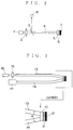
- Fig. 1 shows Japanese Patent Publication No.3-22595 to Matsumura et al. who propose a configuration where the polarizer and the analyzer are replaced by a single polarizer 5. This configuration overcomes the deficiency of the reflection type magnetooptic sensor head proposed by Matsui et al.
- the light emitted from a light source 1 passes through a lens 2 and a half mirror 3.
- the light then enters an optical fiber 4.
- the half mirror 3 permits in part the light incident there upon to pass through and reflects in part.
- a photodetector 18 or power meter placed in the light path 9 serves to measure variations in the intensity of light emitted from the light source 1.
- the signal light directed to the optical fiber 4 passes through a lens 2, half mirror 3 into the optical fiber 4.
- the signal light exiting the optical fiber 4 passes through the polarizer 5 and the Faraday rotator 6 to a reflecting film 7, which is usually made of a metallic thin film.
- the signal light is then reflected by the reflecting film 7 back to the Faraday rotator 6 and then to the polarizer 5.
- the returning light through the polarizer 5 enters the optical fiber 4.
- the returning light exiting the optical fiber 4 enters the half mirror 3 which reflects in part the light into the light path 1.
- the light passing through the light path 1 then enters the photodetector 9 which measures the intensity of the signal light.
- Matsumura et al. employed yttrium iron garnet (Y3Fe5O12), usually referred to as YIG, as a Faraday rotator produced by flux melt technique.
- YIG is advantageous as a Faraday rotator element in that Faraday rotation coefficient(deg/cm) is larger in YIG than in paramagnetic glass and zinc selenide.
- the use of YIG proposed by Matsumura et al. is one way of overcoming the deficiency of a reflection type magnetooptic sensor head proposed by Matsui et al.
- YIG may not be practical as a Faraday rotator since it is well known that YIG transmits lights in near infrared rays having wavelengths longer than 1.1 ⁇ m and absorbs lights in 0.8 ⁇ m band.
- an optical sensor head uses a light source such as semiconductor laser (LD) or light emitting diodes (LED). These light sources have median wavelengths in the range of 0.78-0.85 ⁇ m. Semiconductor laser and light emitting diodes are used as a light source for an optical sensor because they are very inexpensive in the above wavelength range as well as photodetectors have good sensitivity in the range. Using light sources available on the market is most preferred and is the best way to provide inexpensive magnetooptic sensor heads in order to meet the user's needs.
- LD semiconductor laser
- LED light emitting diodes
- the inventors of the present invention investigated many other materials in order to overcome the deficiency of YIG.
- the inventors concluded that bismuth-substituted iron garnets could be used as a magnetooptic material.
- the bismuth-substituted iron garnets can be manufactured rather easily by LPE (Liquid Phase Epitaxial) method, and lends itself to mass production.
- Bismuth-substituted iron garnets are represented by a chemical formula (RBi)3(FeA)5O12, where R represents yttrium Y or rare earth elements and A represents aluminum Al and gallium Ga.
- the Faraday rotation coefficient of a bismuth-substituted iron garnet i.e., the rotation angle of the polarization plane per unit film thickness at saturated magnetization is as large as several times that of YIG, and more specifically about ten times at 0.8 ⁇ m band. This indicates that the film thickness can be smaller with increasing Faraday rotation coefficient for the same magnetooptic effect, achieving less light absorption loss and smaller size.
- the film thickness of an element can be smaller in bismuth-substituted iron garnets than in YIG, indicating less light absorption.
- bismuth-substituted iron garnets are useful in implementing an magnetooptic sensor head with a light source having a wavelength of 0.8 ⁇ m band.
- the magnetic saturation of bismuth-substituted iron garnets ranges from 500 to 1200 Oe which are about half that of YIG (about 1800 Oe). This indicates that the bismuth-substituted iron garnets can be used to measure weak magnetic fields as well.
- the ability to measure weak magnetic fields implies that the absence and presence of the magnetic field can be detected even if the magnetooptic sensor head is located far away from a magnet. This provides more flexibility and higher degrees of freedom in installing the magnetooptic sensor head and suggests wider fields of application for magnetooptic sensor heads.
- reflection type magnetooptic sensor heads can be developed by the use of a bismuth-substituted iron garnet as a Faraday rotator.
- the inventors of the present invention built an engineering model of a reflection type magnetooptic sensor head as shown in Fig. 1 using a Faraday rotator made of a bismuth-substituted iron garnet single crystal in place of YIG.
- the inventors made a variety of experiments for various magnetic field intensities.
- the sensor head failed to detect any light signal regardless of whether the sensor head is applied with a magnetic field.
- the inventors made further various experiments in order to find out the reason why the reflection type magnetooptic sensor head according to Fig. 1 failed to detect the light signals. Having made great many experiments, the inventors finally realized that the sensor head failed to detect light due to the magnetic domain structure of the Faraday rotator.
- a reflection type magnetooptic sensor head can be constructed of a reflecting film, (111) bismuth-substituted iron garnet single crystal, polarizer, and light-inputting/outputting paths. Further, the light-inputting/outputting paths are divided into two light paths; an incoming-light path for the light coming into the polarizer from a light source and an outgoing light path for the light leaving the polarizer back to the light source. The two light paths are aligned such that they make an angle greater than 5 degrees with respect to each other.
- the inventors further continued the research work of magnetooptic sensor heads, and then developed a reflection type magnetooptic sensor head using a Faraday rotator made of a bismuth-substituted iron garnet as disclosed in Japanese Patent Application No.4-90976 (filed on April 10, 1992.).
- Fig. 2 shows the construction of a reflection type magnetooptic sensor head disclosed in Japanese Patent Application No. 4-90976.
- a polarizer is depicted at 10.
- a Faraday rotator 11 is made of a (111) bismuth-substituted iron garnet single crystal film which is magnetized most easily in a direction normal to the film surface. The Faraday rotator 11 is exposed to a magnetic field to be measured.
- a reflecting film 12 reflects a light.
- An optical waveguide 13 for incoming lights is formed on glass or polymer, or is in the form of an optical fiber.
- An optical waveguide 14 for outgoing lights is formed on glass or polymer, or is in the form of an optical fiber.
- the light emitted from a light source 16 is directed through a lens 15 into the incoming light path 13.
- the incoming light path 13 may be directly connected with the light source 16 by omitting the lens 15.
- the light exiting the light path 13 then passes through the polarizer 10, the Faraday rotator 11 to the reflecting film 12.
- the light is then reflected by the reflecting film 12 back through the Faraday rotator 11, the polarizer 10, the light path 14 to a photodetector 17 which detects the light as a light signal.
- the reflection type magnetooptic sensor head in Fig. 2 the light inputting/outputting port has two independent paths 13 and 14 which make an angle ⁇ greater than 5 degrees relative to each other.
- the aforementioned reflection type magnetooptic sensors head using a Faraday rotator made of a bismuth-substituted iron garnet adequately meet the requirements for a magnetooptic sensor head.
- the two light paths must be aligned such that they make an angle ⁇ greater than 5 degrees with respect to each other (Japanese Patent Application No.4-90976)
- the Faraday rotator must be arranged such that the Faraday rotator is at an angle with an axis normal to the polarizer and reflecting mirror
- Japanese Patent Application No.4-116141 filed on May 8, 1992
- the sensor head must be in a unitary construction such that the (111) bismuth-substituted iron garnet single crystal film is sandwiched between slanting surfaces of two rectangular prism (Japanese Patent Application No.4-130674, filed on May 22, 1992).
- This construction is disadvantageous in implementing a sensor probe having a diameter less than 5 millimeters.
- the sensor is no use for measuring a magnetic field in a very narrow space such as a cylinder provided in the rotating shafts of gyros or turbines where the diameters are on the order of several millimeters.
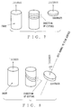
- the Faraday rotator is usually cut from an ingot such that [111] axis is normal to the surface of the Faraday rotator as shown in Fig. 7.
- the inventors has successfully developed a reflection type magnetooptic sensor based on a (111) bismuth-substituted iron garnet single crystal film as a Faraday rotator.
- this sensor was yet to be improved for ease of assembly and alignment. Therefore, the inventors further carried out experiments and research work to meet the requirements in manufacturing sensor heads.
- the present invention is a magnetooptic measuring apparatus where a light inputting/outputting path, polarizer, (111) bismuth-substituted iron garnet single crystal film (Faraday rotator), reflecting film (or mirror) are aligned in this order, and the Faraday rotator is made of a bismuth-substituted iron garnet single crystal film having a [111] axis at an angle ⁇ of 5-60 degrees, preferably 10-45 degrees, with an axis normal to the film surface.
- the reflecting mirror is positioned such that a light incident upon the reflecting mirror is substantially normal to the reflecting surface thereof.
- the present invention commercially provides a very cheap, small size, light weight, easy-to-manufacture reflection type magnetooptic sensor head based on magnetooptic materials having a multidomain structure.
- a reflection type magnetooptic sensor of the invention based on a Faraday rotator made of a bismuth-substituted iron garnet, is constructed of and aligned after a light source in the order of a light inputting/outputting path, polarizer, particular (111) bismuth-substituted iron garnet single crystal film (Faraday rotator), and reflecting film.
- the Faraday rotator or specific bismuth-substituted iron garnet single crystal film of the invention is shown in Fig. 4, and is a particular single crystal whose [111] axis is at an angle ranging from 5 to 60 degrees with an axis normal to the film surface.
- a polarizer 20 is in the form of, for example, POLARCORE.
- a Faraday rotator 21 is made of a specific bismuth-substituted iron garnet single crystal film.
- a reflecting film 22 is made of, for example, a metal thin film and a light inputting/outputting path 23 is in the form of, for example, optical fiber or optical wave guide.
- the light inputting/outputting path 23 may be arranged to serve as a light path for an incoming light while also serving as an optical branching circuit for guiding a light reflected by the reflecting film 22 to a photodetector.
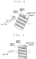
- a Faraday rotator made of a (111) bismuth-substituted iron garnet single crystal film having a multidomain structure is used so that the light emitted from the light inputting/outputting path passes through a plurality of different magnetic domains a and magnetic domains b (refer to Fig. 6).
- the Faraday rotator has an easy axis, i.e., the direction in which Faraday rotator is easily magnetized, at a predetermined angle ⁇ with an axis normal to the film surface.
- the accuracy of measurement can be affected by the variations in intensity of the light source and the light reflected back by reflective surfaces other than the reflecting film.
- These reflective surfaces include the surface of the polarizer and the surface of the bismuth-substituted iron garnet single crystal film.
- the difference ⁇ P in intensity between light signals should be at least 2 dB between when the sensor head is not applied with a magnetic field and when the sensor is substantially magnetically saturated.
- a bismuth-substituted iron garnet single crystal is manufactured by LPE method using a non-magnetic garnet substrate (Thin Solid Films, Vol. 114, p33(1984)).
- a (CaGd)3(ZrMgGa)5O12 substrate is one of non-magnetic garnet substrates and is manufactured by Czochralski method.
- non-magnetic garnet substrates have the least crystal defects in [111] direction (Thin Solid Films, Vol.114, p59(1984).
- the substrate in order to manufacture a non-magnetic garnet substrate having [111] axis at an angle ⁇ with an axis normal to the substrate surface, the substrate has to be cut from the ingot such that [111] axis is at an angle ⁇ with an axis normal to the film surface as shown in Fig. 8.
- the greater the angle ⁇ the less number of substrates manufactured from the ingot. This increases the cost of substrate.
- a dichroic polarizer is preferred for its small thickness and high extinction ratio.
- a bismuth-substituted iron garnet single crystal of the invention can easily be manufactured by using different substrates by LPE method (Thin Solid Films, Vol.114, p33(1984)).
- the non-magnetic garnet substrate used in the present invention is manufactured by cutting an ingot manufactured by Czochralski method such that the aforementioned desired angle ⁇ is obtained, or cutting a non-magnetic garnet [(GdCa)3(GaMgZr)5O12] referred to as an SGGG substrate which has a lattice constant of 12.490-12.515 angstroms and is available as a substrate for LPE on the market.
- the angle ⁇ is selected in the range from 5-60 degrees, preferably from 10-45.
- the non-magnetic substrate on which a bismuth-substituted iron garnet thin film is formed need not be removed.
- the non-magnetic substrate may be preferably left as a support to enhance mechanical strength if the thin film of a bismuth-substituted iron garnet single crystal film is as thin as several tens of microns.
- the non-magnetic substrate may be eliminated by grinding for smaller size of the sensor if the film is as thick as several hundreds of microns.
- the reflection film There is no particular requirement for the reflection film. It is preferred to use a mirror made of a metal film deposited on glass available on the market, a bismuth-substituted iron garnet film, metallic mirror made by depositing gold or aluminum directly on a non-magnetic substrate, or dielectric multilayer mirror made or multilayer of metal oxides such as SiO2 and TiO2.
- the reflection film may be provided either on the side of the bismuth-substituted iron garnet single crystal film or on the side of the substrate.
- the light inputting/outputting do not have to be of a special type.
- the light inputting path may be an optical fiber and the light outputting path may be air and optical wave guides patterned in glass or polymer film, and optical fibers are particularly preferred for mass production and small size of sensors.
- any type of optical fiber may be used for the light paths but, those having core diameters less than 50 ⁇ m causes the width of magnetic domain of a bismuth-substituted iron garnet to affect the characteristics of a sensor, resulting in unstable sensitivity and lower optical coupling efficiency. Diameters greater than 50 ⁇ m are sufficient.
- the reflection type magnetooptic sensor head according to the present invention is connected to a light source and a photodetector through the use of a half mirror shown in Fig. 1 and an optical branching device such as optical wave guides and optical couplers.
- the wavelength of a light source of a magnetooptic measuring apparatus is selected taking into account the sensitivity and light transmittance of a Faraday rotator, the performance and cost of a light source, and the sensitivity of a detector.
- the wavelength of a light source is preferably selected from a near infrared light in the range from 780 to 850 nm for the following reasons.
- Preferable second alternative wavelengths are in the 1300 nm band and 1550 nm band used in optical fiber communications, or 1060 nm at which YAG lasers can be used.
- Wavelengths beyond these ranges results in higher optical absorption and smaller Faraday effect of a bismuth-substituted iron garnet, necessitating the thicker film of a Faraday rotator which in turn makes it difficult to manufacture a Faraday rotator by LPE method.
- Fig. 3 shows a general construction of a first embodiment of the invention.
- a one-inch garnet single crystal [(GdCa)3(GaMgZr)5O12] which is an ingot having a lattice constant equal to 12.498 ⁇ 0.002 angstroms, was cut in such a way that [111] axis of the ingot makes an angle of 5 degrees with an axis normal to the surface of the single crystal film.
- a crystal film obtained is a (111) garnet single crystal [(GdCa)3(GaMgZr)5O12] of a 500 ⁇ m thickness.
- the magnetooptic sensor head was manufactured in the following manner.
- a 500 milliliter platinum crucible was placed on an LPE furnace, which platinum crucible contained therein a lead oxide (PbO, 4N) of 843 grams, a bismuth oxide (Bi2O3, 4N) of 978 grams, a ferric oxide (Fe2O3, 4N) of 128 grams, a boron oxide (B2O3, 5N) of 38 grams, a terbium oxide (Tb4O7, 3N) of 4.0 grams, and a holmium oxide (Ho2O3, 3N) of 9.0 grams.
- the content of the crucible was heated to a temperature of 1000 degrees so that the content in the crucible melts.
- the melted content was sufficiently beaten for a homogeneous mixture and was then cooled down to a melt temperature of 768 degrees to produce a melt for growing a bismuth-substituted iron garnet single crystal.
- a (111) substrate of a garnet single crystal was positioned with one of the two opposed sides thereof being in contact with the thus produced melt for 2.5 hours for epitaxial growth while maintaining the melt temperature at 768 degrees.
- a crystal obtained was a (111) bismuth-substituted iron garnet single crystal having a compound of Ho 1.1 Tb 0.6 Bi 1.3 Fe5O12 [(HoTbBiIG) single crystal] and having a film thickness of 51 ⁇ m. This crystal showed a Faraday rotation ⁇ F of 47.7 degrees at a wavelength 786 nm with saturated magnetization.
- a polarizer 20 (trade name is POLARCORE manufactured by CORNING) applied with an antireflection film was securely attached to the single crystal side of the Faraday rotator/reflecting film block. After the adhesive has cured completely, a polymer clad optical fiber of a core diameter of 400 ⁇ m was attached as a light inputting/outputting path to the polarizer, thus completing the assembly of a magnetooptic sensor head. The signal light is incident upon the Faraday rotator such that the light exiting the Faraday rotator is normal to the reflecting surface of the reflecting film.
- This magnetooptic sensor head in Fig. 3 was used in place of the magnetooptic sensor head of the reflection type magnetooptic shown in Fig. 1. Then, the magnetooptic sensor head was placed in a magnetooptic field applying apparatus (MAGNET manufactured by Magnetic). A light signal of a wavelength of 0.786 ⁇ m was output from a light source (Semiconductor laser, Model LT024MD/PD SEMICONDUCTOR LASER manufactured by Sharp).
- MAGNET magnetooptic field applying apparatus
- the light is transmitted through the lens 2, half mirror 3, light inputting/outputting path (optical fiber) 23, polarizer 20, and Faraday rotator 21 to the reflection film 22, and is then reflected back by the reflecting film 22 through the Faraday rotator 21, polarizer 20, and light inputting/outputting (optical fiber) 23 to the half mirror 3 which directs the light to a photodetector 8 (trade name is Model AQ-111 POWER METER, manufactured by Ando Electric Ltd.), which in turn measures the intensity of the light incident thereupon.
- the Faraday rotator was magnetically saturated when applied with a magnetic field of 1000 Oe.
- a (111) bismuth-substituted iron garnet single crystal film was manufactured in the same way as in Example 1 except that the garnet single crystal (ingot) was cut in such as way that [111] axis of the ingot makes an angle of 20 degrees with an axis normal to the surface of the single crystal film.
- the film thickness was 47 ⁇ m and Faraday rotation ⁇ F was 42.6 degrees at a wavelength of 786 nm with the Faraday rotator being magnetically saturated.
- a magnetooptic sensor head was assembled in the same way as in Example 1 except that the thus manufactured (111) bismuth-substituted iron garnet single crystal film was used. The difference in intensity was 5.0 dB when measured in the same was as in Example 1.
- a (111) bismuth-substituted iron garnet single crystal film was manufactured in the same way as in Example 1 except that the garnet single crystal (ingot) was cut in such as way that [111] axis of the ingot makes an angle of 30 degrees with an axis normal to the surface of the single crystal film.
- the film thickness of thus manufactured was 44 ⁇ m and the Faraday rotation ⁇ F was 40.3 degrees at a wavelength of 786 nm with the Faraday rotator being magnetically saturated.
- a magnetooptic sensor head was assembled in the same way as in Example 1 except that the thus manufactured (111) bismuth-substituted iron garnet single crystal film was used. The difference in intensity was 8.2 dB when measured in the same way as in Example 1.
- the magnetooptic sensor head used in Example 1 was mounted to the input port of an optical branching device (Model 200S-D2, optical fiber having a core diameter of 200 ⁇ m, manufactured by Mitsubishi Gasu Kagaku) in the form of a polymer optical wave guide.
- a semiconductor laser light source (Model KLD-780, manufactured by Kette System Service, stabilized LD light source with a wavelength of 0.786 ⁇ m) was connected to the output port of the optical branching device.
- a photodetector (trade name is POWER METER, Model AQ-111, manufactured by Ando Electric) was connected to the light branching port (Y-branching, optical fiber) of the optical branching device.
- the magnetooptic sensor head was placed in position within a magnetic-field-applying apparatus (Trade name is MAGNET, manufactured by Magnetic).
- the light intensity of a single light entering the photodetector 35 was measured at a wavelength of 0.783 ⁇ m.
- Example 4 Measurement was made with the same construction as Example 4 except that the magnetooptic sensor head of Example 2 was used in place of the magnetooptic sensor head of Example 1. The difference in light intensity was 7.1 dB.
- Example 4 Measurement was with the same construction as Example 4 except that the magnetooptic sensor head of Example 3 was used in place of the magnetooptic sensor head of Example 1. The difference in light intensity was 7.7 dB.
- the difference in light intensity was 3.8 dB.
- a 500 milliliter platinum crucible was placed on an LPE furnace, which platinum crucible contained therein a lead oxide (PbO, 4N) of 843 grams, a bismuth oxide (Bi2O3, 4N) of 978 grams, a ferric oxide (Fe2O3, 4N) of 128 grams, a boron oxide (B2O3, 5N) of 38 grams, a europium oxide (Eu2O3, 3N) of 4.2 grams, and a holmium oxide (Ho2O3, 3N) of 9.0 grams.
- the content of the crucible was heated to a temperature of 1000 degrees so that the content in the crucible melts.
- the melted content was sufficiently beaten for a homogeneous mixture and was then cooled down to a melt temperature of 766 degrees , thus preparing a melt for growing a bismuth-substituted iron garnet single crystal.
- a (111) substrate of a garnet single crystal which has been cut in such as way that [111] axis of the ingot makes an angle of 20 degrees with an axis normal to the surface of the single crystal film, was positioned with one of the two opposed sides thereof being in contact with the thus produced melt for 2.5 hours for epitaxial growth while maintaining the melt temperature at 766 degrees.
- a crystal obtained was a (111) bismuth-substituted iron garnet single crystal film having a compound of Ho 1.1 Eu 0.6 Bi 1.3 Fe5O12 and a film thickness of 45 ⁇ m. This crystal showed a Faraday rotation ⁇ F of 46.1 degrees at a wavelength 783 nm with magnetization saturated at 1200 Oe.
- Example 4 Measurement was made with the same construction as Example 4 except that a magnetooptic sensor head (Faraday rotator was made of Ho 1.1 Eu 0.6 Bi 1.3 Fe5O12 single crystal) was used in place of the magnetooptic sensor head. The difference in light intensity was 5.8 dB.
- a 500 milliliter platinum crucible was placed on an LPE furnace, which platinum crucible contained therein a lead oxide (PbO, 4N) of 843 grams, a bismuth oxide (Bi2O3, 4N) of 978 grams, a ferric oxide (Fe2O3, 4N) of 120 grams, a gallium oxide (Ga2O3, 4N) of 4.5 grams, a boron oxide (B2O3, 5N), a gadollium (Gd2O3, 3N) of 6.5 grams, and an yttrium oxide (Y2O3, 3N) of 4.0 grams.
- the content of the crucible was heated to a temperature of 1000 degrees so that the content in the crucible melts.
- the melted content was sufficiently beaten for a homogeneous mixture and was then cooled down to a melt temperature of 773 degrees to produce a melt for growing a bismuth-substituted iron garnet single crystal.
- a (111) substrate of a garnet single crystal substrate which has been cut from an ingot of (GdCa)3(GaMgZr)5O12 in such a way that [111] axis makes an angle of 20 degrees with an axis normal to the surface of the substrate, was positioned with one of the two opposed sides thereof being in contact with the thus produced melt for 3.0 hours for epitaxial growth while maintaining the melt temperature at 773 degrees.
- a crystal obtained was a (111) bismuth-substituted iron garnet single crystal having a compound of Gd 0.9 Y 0.9 Bi 1.2 Fe 4.8 Ga 0.2 O12 and a film thickness of 46 ⁇ m. This crystal showed a Faraday rotation ⁇ F of 42.7 degrees at a wavelength of 783 nm with magnetization saturated at 600 Oe.
- Example 4 Measurement was made with the same construction as Example 4 except that the thus produced magnetooptic sensor head (Faraday rotator is made of single crystal Gd 0.9 Y 0.9 Bi 1.2 Fe 4.8 Ga 0.2 O12 was used in place of the magnetooptic sensor head of Example 1. The difference in light intensity was 4.5 dB.
- Faraday rotator is made of single crystal Gd 0.9 Y 0.9 Bi 1.2 Fe 4.8 Ga 0.2 O12 was used in place of the magnetooptic sensor head of Example 1.
- the difference in light intensity was 4.5 dB.
- a (111) substrate of a garnet single crystal was manufactured with the same conditions as in Example 1 except that the bismuth-substituted iron garnet single crystal was cut from an ingot in such a way that [111] axis makes an angle of 3 degrees with an axis normal to the surface of the substrate.
- a crystal obtained was a (111) bismuth-substituted iron garnet single crystal film having a film thickness of 50 ⁇ m. This crystal film showed a Faraday rotation ⁇ F of 45.9 degrees at a wavelength of 786 nm with saturated magnetization.
- a magnetooptic sensor head was manufactured with the same construction as in Example 1 except that the (111) bismuth-substituted iron garnet single crystal of the comparison 1 was used. Measurement was made in the same way as in Example 1, and the difference in light intensity was 1.7 dB.
Landscapes
- Engineering & Computer Science (AREA)
- Power Engineering (AREA)
- Physics & Mathematics (AREA)
- Condensed Matter Physics & Semiconductors (AREA)
- General Physics & Mathematics (AREA)
- Measuring Magnetic Variables (AREA)
Applications Claiming Priority (2)
| Application Number | Priority Date | Filing Date | Title |
|---|---|---|---|
| JP4142929A JPH05333124A (ja) | 1992-06-03 | 1992-06-03 | 反射型光磁界センサヘッド |
| JP142929/92 | 1992-06-03 |
Publications (2)
| Publication Number | Publication Date |
|---|---|
| EP0573007A2 true EP0573007A2 (de) | 1993-12-08 |
| EP0573007A3 EP0573007A3 (en) | 1994-06-15 |
Family
ID=15326926
Family Applications (1)
| Application Number | Title | Priority Date | Filing Date |
|---|---|---|---|
| EP19930108865 Ceased EP0573007A3 (en) | 1992-06-03 | 1993-06-02 | Magneto-optic sensor head |
Country Status (3)
| Country | Link |
|---|---|
| US (1) | US5463316A (de) |
| EP (1) | EP0573007A3 (de) |
| JP (1) | JPH05333124A (de) |
Cited By (1)
| Publication number | Priority date | Publication date | Assignee | Title |
|---|---|---|---|---|
| RU2234114C1 (ru) * | 2002-11-14 | 2004-08-10 | Военный инженерно-космический университет | Магнитооптический вентиль |
Families Citing this family (10)
| Publication number | Priority date | Publication date | Assignee | Title |
|---|---|---|---|---|
| US5566017A (en) * | 1994-08-04 | 1996-10-15 | Fdk Corporation | Material for magneto-optical element and faraday rotator using the same |
| RU2138069C1 (ru) * | 1996-04-23 | 1999-09-20 | Гарнетек Лтд. (Garnetec Ltd.) | Магнитооптическая тонкопленочная структура |
| US5719497A (en) * | 1996-05-09 | 1998-02-17 | The Regents Of The University Of California | Lensless Magneto-optic speed sensor |
| JPH1144744A (ja) * | 1997-07-29 | 1999-02-16 | Mitsubishi Gas Chem Co Inc | 反射型光磁界センサ |
| WO2000023811A1 (en) | 1998-10-21 | 2000-04-27 | Duncan Paul G | Methods and apparatus for optically measuring polarization rotation of optical wave fronts using rare earth iron garnets |
| JP2002311402A (ja) * | 2001-04-11 | 2002-10-23 | Minebea Co Ltd | ファラデー回転子 |
| JP2002311387A (ja) * | 2001-04-17 | 2002-10-23 | Minebea Co Ltd | 多段反射型ファラデー回転子 |
| GB0228657D0 (en) * | 2002-12-09 | 2003-01-15 | Black & Decker Inc | Planer |
| CN102268733A (zh) * | 2011-08-02 | 2011-12-07 | 中国科学院合肥物质科学研究院 | 具有矩形磁滞回线和高矫顽磁场的磁光晶体及制备方法 |
| EP3690466A4 (de) * | 2017-09-29 | 2021-06-23 | Citizen Finedevice Co., Ltd. | Magnetisches sensorelement und magnetische sensorvorrichtung |
Citations (1)
| Publication number | Priority date | Publication date | Assignee | Title |
|---|---|---|---|---|
| EP0046298A1 (de) * | 1980-08-18 | 1982-02-24 | Hitachi, Ltd. | Apparat zum Messen eines magnetischen Feldes |
Family Cites Families (11)
| Publication number | Priority date | Publication date | Assignee | Title |
|---|---|---|---|---|
| JPS5655811A (en) * | 1979-10-15 | 1981-05-16 | Mitsubishi Electric Corp | Sensor |
| JPS5865414A (ja) * | 1981-09-28 | 1983-04-19 | Nec Corp | 磁気光学素子 |
| JPH0766044B2 (ja) * | 1985-06-29 | 1995-07-19 | 株式会社東芝 | 磁界センサ |
| JPS62150185A (ja) * | 1985-12-24 | 1987-07-04 | Matsushita Electric Ind Co Ltd | 磁界測定装置 |
| US4952014A (en) * | 1987-10-19 | 1990-08-28 | At&T Bell Laboratories | Optical systems with thin film polarization rotators and method for fabricating such rotators |
| US4818080A (en) * | 1987-11-05 | 1989-04-04 | General Electric Company | Monolithic faraday optical switch |
| US5038102A (en) * | 1988-12-27 | 1991-08-06 | Amespace, Inc. | Speed sensor utilizing magneto-optics switch actuated by magnetic field rotation |
| JPH0775277B2 (ja) * | 1989-06-20 | 1995-08-09 | 日本電気株式会社 | 屋外用表示装置の内部熱排出装置 |
| JPH0354198A (ja) * | 1989-07-20 | 1991-03-08 | Shin Etsu Chem Co Ltd | 酸化物ガーネット単結晶 |
| DE9015613U1 (de) * | 1989-12-22 | 1991-01-31 | Iveco Magirus AG, 7900 Ulm | Vorrichtung zur Messung einer physikalischen Größe mit Hilfe eines faseroptischen Sensors unter Ausnutzung des Farraday-Effektes |
| JPH0782164B2 (ja) * | 1991-04-25 | 1995-09-06 | 松下電器産業株式会社 | 磁気光学素子及び磁界測定装置 |
-
1992
- 1992-06-03 JP JP4142929A patent/JPH05333124A/ja active Pending
-
1993
- 1993-06-02 US US08/070,684 patent/US5463316A/en not_active Expired - Fee Related
- 1993-06-02 EP EP19930108865 patent/EP0573007A3/en not_active Ceased
Patent Citations (1)
| Publication number | Priority date | Publication date | Assignee | Title |
|---|---|---|---|---|
| EP0046298A1 (de) * | 1980-08-18 | 1982-02-24 | Hitachi, Ltd. | Apparat zum Messen eines magnetischen Feldes |
Cited By (1)
| Publication number | Priority date | Publication date | Assignee | Title |
|---|---|---|---|---|
| RU2234114C1 (ru) * | 2002-11-14 | 2004-08-10 | Военный инженерно-космический университет | Магнитооптический вентиль |
Also Published As
| Publication number | Publication date |
|---|---|
| JPH05333124A (ja) | 1993-12-17 |
| US5463316A (en) | 1995-10-31 |
| EP0573007A3 (en) | 1994-06-15 |
Similar Documents
| Publication | Publication Date | Title |
|---|---|---|
| US6437885B1 (en) | Semiconductor sensor for optically measuring polarization rotation of optical wavefronts using rare earth iron garnets | |
| US5493222A (en) | Reflection type magnetooptic sensor head with faraday rotator | |
| US5719497A (en) | Lensless Magneto-optic speed sensor | |
| EP0510621B1 (de) | Magnetooptisches Element und Magnetfeldmessgerät | |
| US4560932A (en) | Magneto-optical converter utilizing Faraday effect | |
| EP0236345B1 (de) | Optische systeme mit antireziproken polarisationsdrehern | |
| WO1990000256A1 (en) | Magneto-optic current sensor | |
| US5463316A (en) | Magnetooptic sensor head | |
| JPH0766044B2 (ja) | 磁界センサ | |
| US20020145414A1 (en) | Magneto-optic current sensor | |
| EP0046298A1 (de) | Apparat zum Messen eines magnetischen Feldes | |
| US6128423A (en) | Reflection type magneto-optic sensor | |
| US6160396A (en) | Optical magnetic field sensor probe | |
| EP0577114A2 (de) | Magnetooptischer Sensorkopf vom Reflexionstyp | |
| EP0565085A2 (de) | Magnetfeldsensor | |
| Aoyama et al. | A new Faraday rotator using a thick Gd: YIG film grown by liquid-phase epitaxy and its applications to an optical isolator and optical switch | |
| EP0785454A1 (de) | Faraday-Rotator für magneto-optische Sensoren | |
| JP3114765B2 (ja) | 光磁界センサ | |
| JP2004219137A (ja) | 反射型光磁界センサヘッド | |
| JP3148024B2 (ja) | 反射型光磁界センサヘッド | |
| JPH1031057A (ja) | 反射型光磁界センサヘッド | |
| JPH0618639A (ja) | 反射型光磁界センサヘッド | |
| EP0647869A1 (de) | Nicht-reziprokes optisches Gerät | |
| JPH06222120A (ja) | 反射型光磁界センサヘッド | |
| JP3269101B2 (ja) | 磁気光学膜 |
Legal Events
| Date | Code | Title | Description |
|---|---|---|---|
| PUAI | Public reference made under article 153(3) epc to a published international application that has entered the european phase |
Free format text: ORIGINAL CODE: 0009012 |
|
| AK | Designated contracting states |
Kind code of ref document: A2 Designated state(s): DE FR GB |
|
| PUAL | Search report despatched |
Free format text: ORIGINAL CODE: 0009013 |
|
| AK | Designated contracting states |
Kind code of ref document: A3 Designated state(s): DE FR GB |
|
| 17P | Request for examination filed |
Effective date: 19941215 |
|
| 17Q | First examination report despatched |
Effective date: 19970306 |
|
| GRAG | Despatch of communication of intention to grant |
Free format text: ORIGINAL CODE: EPIDOS AGRA |
|
| STAA | Information on the status of an ep patent application or granted ep patent |
Free format text: STATUS: THE APPLICATION HAS BEEN REFUSED |
|
| 18R | Application refused |
Effective date: 19980221 |