EP0573121B1 - Procédé et appareil pour commander une machine de peignage - Google Patents
Procédé et appareil pour commander une machine de peignage Download PDFInfo
- Publication number
- EP0573121B1 EP0573121B1 EP93201580A EP93201580A EP0573121B1 EP 0573121 B1 EP0573121 B1 EP 0573121B1 EP 93201580 A EP93201580 A EP 93201580A EP 93201580 A EP93201580 A EP 93201580A EP 0573121 B1 EP0573121 B1 EP 0573121B1
- Authority
- EP
- European Patent Office
- Prior art keywords
- machine
- gripper unit
- sensor
- combing
- halt
- Prior art date
- Legal status (The legal status is an assumption and is not a legal conclusion. Google has not performed a legal analysis and makes no representation as to the accuracy of the status listed.)
- Revoked
Links
- 238000000034 method Methods 0.000 title claims description 16
- 230000009471 action Effects 0.000 claims description 24
- 239000004744 fabric Substances 0.000 claims description 19
- 239000000835 fiber Substances 0.000 claims description 19
- 230000033001 locomotion Effects 0.000 claims description 16
- 230000009467 reduction Effects 0.000 claims description 4
- 230000005540 biological transmission Effects 0.000 claims description 3
- 230000007246 mechanism Effects 0.000 claims description 3
- 230000003287 optical effect Effects 0.000 claims description 2
- 230000008901 benefit Effects 0.000 description 3
- 239000000463 material Substances 0.000 description 3
- 125000004122 cyclic group Chemical group 0.000 description 2
- 230000004913 activation Effects 0.000 description 1
- 230000000254 damaging effect Effects 0.000 description 1
- 230000007547 defect Effects 0.000 description 1
- 230000000694 effects Effects 0.000 description 1
Images


Classifications
-
- D—TEXTILES; PAPER
- D01—NATURAL OR MAN-MADE THREADS OR FIBRES; SPINNING
- D01G—PRELIMINARY TREATMENT OF FIBRES, e.g. FOR SPINNING
- D01G19/00—Combing machines
- D01G19/06—Details
- D01G19/26—Driving arrangements
-
- D—TEXTILES; PAPER
- D01—NATURAL OR MAN-MADE THREADS OR FIBRES; SPINNING
- D01G—PRELIMINARY TREATMENT OF FIBRES, e.g. FOR SPINNING
- D01G19/00—Combing machines
- D01G19/06—Details
- D01G19/14—Drawing-off and delivery apparatus
- D01G19/16—Nipper mechanisms
Definitions
- This invention relates to a method and device for controlling a combing machine.
- Fibre combing in a combing machine is known to involve a plurality of synchronously operated members.
- the actual combing is effected cyclically by a circular comb, the toothed portion of which penetrates between the tufts of the fibre cloth while this is engaged between the elements of the gripper unit during rearward movement and also partly during advancement.
- the teeth of the circular comb remove the individual ungripped fibres to produce a combed web, the removed fibres being discarded.
- Coordination of these and other moving machine members is achieved mechanically by transmissions and crank mechanisms which receive motion from a single electric motor.
- the condition of the fibres may be such that on re-starting the machine an excessive discarding of material occurs. A combing discontinuity or irregularity can therefore result, leading to a loss in quality of the web leaving the machine.
- An object of the present invention is to overcome the difficulties connected with the stoppage of a combing machine by improving the quality and uniformity of the web following machine stoppage and reducing the discarding of material during machine re-starting.
- a further object is to provide a method and device for controlling a combing machine which maintains combing continuity and reduces the time involved by personnel during machine re-starting.
- the present invention is relating to a method for controlling a combing machine in which a fibre cloth is subjected cyclically to the action of a circular comb and of a gripper unit which retains the fibre cloth during combing, the fibre cloth being temporarily released from the action of the gripper unit when the combing action by the circular comb ceases.
- the objects cited above are attained according to the present invention in that the stoppage of the machine is controlled such that the machine is halted always and only when the gripper unit is substantially in its position of maximum opening or maximum advancement.
- the inertial deceleration of the machine is monitored and on attaining a determined reduction in its speed of movement a braking action is produced to halt the machine substantially when the gripper unit is in its position of maximum opening or maximum advancement.
- the method of the invention is implemented by a control device in a combing machine in which the members involved in the combing are operated by a motor via transmissions and crank mechanisms, and a gripper unit arranged to temporarily grip a fibre cloth cooperates with a circular comb arranged to comb the fibre cloth during the gripping of the fibre cloth by the gripper unit, characterised in that position sensor means are associated with the gripper unit, said sensor means being operationally connected to a halting device which on the basis of the sensing by said sensor means is caused to halt the machine substantially when the gripper unit is in its position of maximum opening or maximum advancement.
- the halting device comprises a brake operated after a determined number of rocking movements of the rocking drive means for the gripper unit, as measured by said sensor means starting from a halt signal fed to said motor.
- the machine is halted each time in a position in which the combing members are always in the same operating state, namely in a position in which these are not acting on the fibre cloth and the gripper unit is completely open.
- this situation gives the best conditions for re-starting the machine and hence the combing, in which there are no damaging effects on the fibres, and combing continuity and hence product quality are maintained.
- On re-starting production from said halt conditions it has been found that a lesser quantity of material has to be discarded, so increasing machine efficiency.
- the personnel requirement during re-starting can also be limited because of the advantageous restart conditions, which are always the same given that the machine is halted always and only when the grippers are completely open or at maximum advancement.
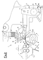
- a combing machine 1 with a fixed frame 2 comprises, in known manner, means (not shown) for feeding a fibre cloth 3 to the combing members, consisting essentially of a gripper unit 4 cooperating with a circular comb 5.
- a feed roller 6 guides the fibre cloth 3 within the combing region, while grabbing rollers 7 and 8 move the combed web forwards and rearwards synchronously with the action of the combing members.
- a rectilinear comb 9 cooperates in the combing action in known manner.
- the gripper unit 4 comprises essentially an upper gripper element 10 and a lower gripper element 11. This latter is fixed to a bar 12 pivoted at points 13 and 14 at its ends to rocker arms 15 and 16 respectively, these being supported by shafts 17 and 18.
- the arm 16, rigid with the shaft 18, is driven with rocking movement in known manner.
- the arm 15 is supported idly on the shaft 17.
- the upper gripper arm 10 is fixed to an arm 19 pivoted at 20 to the bar 12 and at 21 to an expandable element 22 pivoted at 23 to the fixed structure 2.
- the rectilinear comb 9 is fixed by a block 24 to a support 25 rigidly fixed in known manner to the bar 12.
- the circular comb 5 is rigid with the shaft 17 and comprises a toothed sector 26 of known type.
- the angular arrangement of the toothed sector 26, ie the angular position in which the circular comb 5 is fixed onto the shaft 17, is such that the fibre cloth 3 is engaged during combing when the gripper unit 4 is closed and moving rearwards, as indicated in Figure 2.
- the moving members of the machine are driven by an electric motor 27 ( Figure 3), which by way of a belt drive 28 and pulleys rotates a first shaft 29, on which a pinion 30 is keyed to engage a gear wheel 31 fixed to the shaft 17.
- the shaft 29 transmits movement to certain machine members in known manner, while the shaft 17 rotates the circular comb 5 and transmits movement to the grabbing rollers 7 and 8 in known manner.
- the stoppage of the machine consequent on the opening of a switch 34 which interrupts power to the motor 27, is controlled such that the machine stops always and only when the gripper unit 4 is substantially in its position of maximum opening or of maximum advancement.
- the gripper unit 4 comprises associated position sensor means, consisting preferably of a sensor 35 for sensing the position of the rocker arm 16, which are operationally connected to a halting device 36 controlled by an electronic control unit 37 on the basis of the determination by said sensor means such as to halt the machine when the gripper unit 4 is in its completely open position.
- the sensor 35 comprises a confronting element 35a and a magnetic sensor element 35b, one fixed to the arm 16 operating the gripper unit 4 and the other fixed to the machine fixed structure 2 so that they face each other when the gripper unit 4 is in its open position, as shown in Figure 1.
- One of the magnetic elements acts as a magnetic field generator and the other as an impedance.
- the element 35a causes cyclic variations in the magnetic field of the element 35b with a frequency corresponding to the frequency with which the confronting element 35a passes in front of the element 35b. These cyclic variations are transformed into electrical signals or pulses, which are fed to the control unit 37 via the line 39.
- the elements 35a and 35b are preferably positioned so that they face each other when the gripper unit 4 is in its position of maximum opening.
- the sensor means When the machine is operating normally the sensor means are either disconnected or the relative signals are ignored by the control unit 37, as it is not operative.
- the control unit 37 When the machine is halted by opening the switch 34, the control unit 37 is made operative by receiving an activation signal via the line 40 which connects it to the switch 34.
- the rocker arm 16 undergoes a few more rocking movements, which are sensed by the sensor 35 and fed in the form of signals or pulses to the control unit 37.
- a braking action is produced by feeding a rapid braking signal through the line 41 to the halting device 36, which can advantageously be an electromagnetic brake, so as to halt the machine when the gripper unit 4 is in its open state.
- the brake 36 can be operated a determined time after the machine halt command (opening of the switch 34) has been given, or when the control unit 37 has received a predetermined number of pulses from the sensor 35 corresponding to a determined number of rocking movements of the means which operate the gripper unit 4, ie when the machine is almost at rest and the braking action applied by the brake results in instantaneous stoppage.
- the stop signal is provided by the control unit 37 just prior to a new signal from the sensor 35, so that effective stoppage is achieved with the elements 35a and 35b facing each other, this position corresponding to maximum opening of the gripper unit 4 in accordance with Figure 1.
- the control unit 37 can be programmed to measure the time between successive pulses, and to feed the stop signal to the brake 36 when after measuring a predetermined time between one pulse and the next a time has passed since this latter pulse which when added to the time required for the braking action to effectively halt the machine corresponds to the time at which the unit 37 would receive the next pulse.
- the brake 36 could act as soon as the control unit 37 is made operative, the braking action being proportioned so that effective stoppage is achieved when the elements 35a and 35b of the position sensor 35 are aligned.
- the position in which the machine stops does not necessarily have to coincide exactly with that of maximum opening or advancement of the gripper unit 4.
- a certain tolerance in the opening of the grippers is admissible, provided that the combed fibres are superimposed on those previously combed.
- a sensor of another type, such as a proximity sensor or optical sensor, could be used instead of a magnetic position sensor.
- the circular comb 5 comprises an appendix 42 extending through a certain arc downstream (in the direction of rotation of the comb) of the toothed sector 26 and having a radius slightly less than the radius of the toothed sector 26.
- the appendix 42 faces a wall 43 very close to it.
- the appendix 42 and the fixed wall 43 substantially restrict the suction area below the fibres. This restriction causes a substantial reduction in the suction action, which would otherwise be of constant intensity. This prevents the fibres being deviated towards the suction region during the gripper opening, so ensuring correct combing action.
- the method and device of the invention have the advantage of reducing the machine down-time and increasing machine efficiency, because of lesser problems during re-starting.
- the method and device of the present invention can also be easily applied to combing machines already in use.
- the position sensor can also be associated with the gripper unit 4 in a manner different from that shown, for example it can be associated with the bar 12.
Landscapes
- Engineering & Computer Science (AREA)
- Textile Engineering (AREA)
- Preliminary Treatment Of Fibers (AREA)
Claims (15)
- Procédé de contrôle d'une peigneuse, dans lequel un tissu de fibres est soumis de façon cyclique à l'action d'un peigne cylindrique d'une unité à pinces qui retient le tissu pendant le peignage, le tissu étant temporairement libéré de l'action de l'unité à pinces lorsque l'action de peignage par le peigne circulaire cesse, caractérisé en ce que l'arrêt de la machine est contrôlé de manière que la machine soit arrêtée toujours, et seulement, lorsque l'unité à pinces est sensiblement dans sa position d'ouverture maximale ou d'avancement maximal.
- Procédé selon la revendication 1, caractérisé en ce que la décélération inertielle de la machine est surveillée et, lorsqu'on atteint une réduction déterminée de sa vitesse de déplacement, une action de freinage est produite pour arrêter la machine sensiblement lorsque l'unité à pinces est sensiblement dans sa position d'ouverture maximale ou d'avancement maximal.
- Procédé selon la revendication 1, caractérisé en ce que le nombre de mouvements de balancement de l'unité à pinces est mesuré à partir du moment auquel la commande d'arrêt machine est délivrée, et, lorsqu'un nombre prédéterminé de mouvements de balancement a été atteint, une action de freinage est produite pour amener la machine à un arrêt lorsque l'unité à pinces est sensiblement complètement ouverte.
- Procédé selon la revendication 1, caractérisé en ce que le temps qui s'est écoulé depuis le moment auquel la commande d'arrêt machine a été délivré est mesuré et, lorsqu'un temps prédéterminé a été atteint, une action de freinage est produite pour amener la machine à un arrêt lorsque l'unité à pinces est sensiblement complètement ouverte.
- Procédé selon la revendication 1 ou 4, caractérisé en ce que le temps entre des impulsions successives correspondant à des mouvements de balancement successifs effectués par l'unité à pinces pendant la décélération inertielle est mesuré, et en ce qu'une action de freinage est initiée lorsque le temps entre une impulsion et la suivante est égal à un temps prédéterminé et qu'il s'est écoulé depuis cette dernière impulsion un temps qui, ajouté au temps nécessaire pour arrêter effectivement la machine, correspond au temps auquel la prochaine impulsion serait émise.
- Procédé selon la revendication 1, caractérisé en ce que, depuis le moment auquel la commande d'arrêt machine est délivrée, une action de freinage proportionnée est exercée, en sorte de conduire à l'arrêt effectif de la machine lorsque l'unité à pinces est sensiblement complètement ouverte.
- Dispositif pour mettre en oeuvre le procédé selon l'une quelconque des revendications précédentes, dans une peigneuse (1) dans laquelle les éléments impliqués dans le peignage sont actionnés par un moteur (27) par l'intermédiaire de transmissions et de mécanismes contre-coudés, et une unité à pinces (10, 11) agencée pour saisir temporairement un tissu (3) coopère avec un peigne circulaire (5) agencé pour peigner le tissu (3) pendant la saisie du tissu (3) par l'unité à pinces (10, 11), caractérisé en ce que des moyens capteurs de position (35) sont associés à l'unité à pinces (10, 11), lesdits moyens capteurs (35) étant reliés de manière opérationnelle à un dispositif d'arrêt (36) qui, sur la base de la détection effectuée par lesdits moyens capteurs (35), est conduit à arrêter la machine sensiblement lorsque l'unité à pinces (10, 11) se trouve dans sa position d'ouverture maximale ou d'avancement maximal.
- Dispositif selon la revendication 7, caractérisé en ce que le dispositif d'arrêt (36) comprend un frein actionné après un nombre déterminé de mouvements de balancement des moyens d'entraînement en balancement prévus pour l'unité à pinces (10, 11), telle que mesuré par lesdits moyens capteurs (35) en partant d'un signal d'arrêt envoyé audit moteur (27).
- Dispositif selon la revendication 7 ou 8, caractérisé en ce que lesdits moyens capteurs (35) comprennent un capteur de position constitué d'éléments capteurs (35a, 35b) agencés respectivement sur la structure fixe de la machine (2) et sur un bras oscillant (16) entraînant l'unité à pinces (10, 11), ledit élément (35a, 35b) émettant des signaux à chaque mouvement de basculement dudit bras (16) et étant connecté à une unité de commande (37) destinée à traiter lesdits signaux et à actionner ledit dispositif d'arrêt (36) sur la base desdits signaux.
- Dispositif selon la revendication 9, caractérisé en ce que ledit capteur (35) est un capteur magnétique (35a, 35b).
- Dispositif selon la revendication 9 ou 10, caractérisé en ce que lesdits éléments capteurs (35a, 35b) sont agencés pour se faire face l'un l'autre lorsque l'unité à pinces (10, 11) se trouve dans sa position d'ouverture maximale.
- Dispositif selon la revendication 9, caractérisé en ce que ledit capteur de position (35) est un capteur de proximité.
- Dispositif selon la revendication 9, caractérisé en ce que ledit capteur (35) est un capteur optique.
- Dispositif selon une ou plusieurs des revendications 7 à 13, caractérisé en ce que ledit dispositif d'arrêt (36) est un frein électromagnétique actionné par ladite unité de commande (37).
- Dispositif selon une ou plusieurs des revendications 7 à 24, caractérisé en ce que le peigne circulaire (5) comprend un appendice (42) s'étendant sur un arc circulaire adjacent à un secteur denté (26) du peigne (5), dans une position telle que, lorsque l'unité à pinces (10, 11) se trouve dans sa position ouverte, ledit appendice (42) fait face à une paroi fixe (43) afin de limiter la zone d'aspiration dans la région située sous les fibres.
Applications Claiming Priority (2)
| Application Number | Priority Date | Filing Date | Title |
|---|---|---|---|
| ITMI921362A IT1260518B (it) | 1992-06-03 | 1992-06-03 | Procedimento e dispositivo per il controllo di una macchina pettinatrice |
| ITMI921362 | 1992-06-03 |
Publications (2)
| Publication Number | Publication Date |
|---|---|
| EP0573121A1 EP0573121A1 (fr) | 1993-12-08 |
| EP0573121B1 true EP0573121B1 (fr) | 1996-01-17 |
Family
ID=11363444
Family Applications (1)
| Application Number | Title | Priority Date | Filing Date |
|---|---|---|---|
| EP93201580A Revoked EP0573121B1 (fr) | 1992-06-03 | 1993-06-02 | Procédé et appareil pour commander une machine de peignage |
Country Status (5)
| Country | Link |
|---|---|
| US (1) | US5369844A (fr) |
| EP (1) | EP0573121B1 (fr) |
| DE (1) | DE69301338T2 (fr) |
| ES (1) | ES2081683T3 (fr) |
| IT (1) | IT1260518B (fr) |
Families Citing this family (12)
| Publication number | Priority date | Publication date | Assignee | Title |
|---|---|---|---|---|
| IT1280136B1 (it) * | 1995-02-28 | 1998-01-05 | Vouk Macchine Tessili Spa | Macchina pettinatrice a gestione elettronica con sistema perfezionato nella disposizione degli encoders |
| IT1280137B1 (it) * | 1995-02-28 | 1998-01-05 | Vouk Macchine Tessili Spa | Macchina pettinatrice a gestione elettronica con sistema perfezionato nel rilevamento degli impulsi dagli encoders |
| IT1280138B1 (it) * | 1995-02-28 | 1998-01-05 | Vouk Macchine Tessili Spa | Macchina pettinatrice a gestione elettronica con sistema perfezionato per la rimessa in fase |
| US5517725A (en) * | 1995-03-27 | 1996-05-21 | Mandl; Gerhard | Comber machine |
| DE19641979B4 (de) * | 1996-10-11 | 2007-01-04 | Maschinenfabrik Rieter Ag | Verfahren und Vorrichtung zum Steuern der Antriebsbewegungen einer Kämmaschine, insbesondere einer Baumwollkämmaschine |
| EP0936292B1 (fr) * | 1998-02-12 | 2004-02-25 | Maschinenfabrik Rieter Ag | Entrainement de peigne circulaire |
| DE19951126A1 (de) * | 1999-10-23 | 2001-04-26 | Staedtler & Uhl | Fixkamm |
| CN100451191C (zh) * | 2004-12-24 | 2009-01-14 | 经纬纺织机械股份有限公司 | 精梳机的分离罗拉的传动装置 |
| ITMI20050975A1 (it) * | 2005-05-26 | 2006-11-27 | Marzoli Spa | Cilindro strappatore per macchine di pettinatura di fibre tessili |
| CN100409126C (zh) * | 2005-06-30 | 2008-08-06 | 上海纺织机械总厂 | 一种具有工业总线的精梳机控制系统 |
| DE102006020589B4 (de) * | 2006-05-02 | 2010-06-02 | Oerlikon Textile Gmbh & Co. Kg | Antriebswelle für die Speisewalzen einer Kämmmaschine |
| CH719062A9 (de) * | 2021-10-14 | 2023-06-30 | Rieter Ag Maschf | Kämmvorrichtung zum Kämmen eines Fasermaterials. |
Family Cites Families (10)
| Publication number | Priority date | Publication date | Assignee | Title |
|---|---|---|---|---|
| US2895177A (en) * | 1953-10-12 | 1959-07-21 | Tmm Research Ltd | Textile combing machines |
| FR1419881A (fr) * | 1964-10-23 | 1965-12-03 | Schlumberger Cie N | Perfectionnements à la commande du mouvement de rotation alternatif des cylindres arracheurs d'une peigneuse rectiligne |
| US3479699A (en) * | 1966-10-10 | 1969-11-25 | Maremont Corp | Combers |
| JPS5769421A (en) * | 1980-10-20 | 1982-04-28 | Olympus Optical Co Ltd | Position controller |
| JPH0646367B2 (ja) * | 1986-09-29 | 1994-06-15 | 株式会社エスジ− | 位置決め制御における進み角補償方式 |
| DE58907736D1 (de) * | 1988-04-19 | 1994-07-07 | Rieter Ag Maschf | Kämmaschine - Einzelkopfüberwachung. |
| JPH0786776B2 (ja) * | 1988-11-12 | 1995-09-20 | 三田工業株式会社 | 移動体の制御装置 |
| CH676721A5 (fr) * | 1988-12-23 | 1991-02-28 | Rieter Ag Maschf | |
| CH680670A5 (fr) * | 1990-01-17 | 1992-10-15 | Rieter Ag Maschf | |
| JP2763968B2 (ja) * | 1990-05-02 | 1998-06-11 | マシーネンフアブリーク リーテル アクチエンゲゼルシヤフト | ラップ処理機械におけるラップの接合方法及びラップ処理機械 |
-
1992
- 1992-06-03 IT ITMI921362A patent/IT1260518B/it active IP Right Grant
-
1993
- 1993-06-02 DE DE69301338T patent/DE69301338T2/de not_active Revoked
- 1993-06-02 EP EP93201580A patent/EP0573121B1/fr not_active Revoked
- 1993-06-02 ES ES93201580T patent/ES2081683T3/es not_active Expired - Lifetime
- 1993-06-03 US US08/070,809 patent/US5369844A/en not_active Expired - Fee Related
Also Published As
| Publication number | Publication date |
|---|---|
| US5369844A (en) | 1994-12-06 |
| ES2081683T3 (es) | 1996-03-16 |
| ITMI921362A1 (it) | 1993-12-03 |
| IT1260518B (it) | 1996-04-09 |
| ITMI921362A0 (it) | 1992-06-03 |
| DE69301338D1 (de) | 1996-02-29 |
| DE69301338T2 (de) | 1996-08-29 |
| EP0573121A1 (fr) | 1993-12-08 |
Similar Documents
| Publication | Publication Date | Title |
|---|---|---|
| EP0573121B1 (fr) | Procédé et appareil pour commander une machine de peignage | |
| US4059946A (en) | Method and apparatus for start-spinning a thread on open-end spinning units | |
| US4948057A (en) | Device and process to guide, hold and convey a yarn during bobbin replacement | |
| US6045081A (en) | Method and apparatus for winding a continuously advancing yarn | |
| JP2990457B2 (ja) | 破損印刷物の取出し方法及び装置 | |
| US4080775A (en) | Yarn piecing process and apparatus for an open end spinning assembly | |
| JPS59230933A (ja) | 紙葉層を作業周期に即応して次位加工機に移送するための方法及び装置 | |
| US4228642A (en) | Method and apparatus for stopping an open-end spinning machine | |
| EP1460155B1 (fr) | Machine textile avec broche à entraînement individuel où les entraînement individuels sont divisés en unités | |
| JPH11217161A (ja) | 連続的に走入する糸を案内しかつ切断する装置及び方法 | |
| US5154209A (en) | Positive feed picking device for a fluid jet loom | |
| CN1112612A (zh) | 棉条监测装置 | |
| EP1232093B1 (fr) | Dispositif de tensionnement pour machines a lier | |
| US4163358A (en) | Apparatus for controlling the driving of an open-end spinning machine | |
| US5353582A (en) | System for controlling the movement of an elongated textile structure | |
| CA2369940C (fr) | Dispositif de transport de feuilles | |
| US4222224A (en) | Device for temporarily stopping the operation of spinning stations | |
| US4054024A (en) | Apparatus for stopping and restarting the operation of an open-end spinning system | |
| US5430917A (en) | Method and apparatus for piecing lap sheets | |
| JP4140785B2 (ja) | 材料送り装置の制御装置 | |
| CN115803485A (zh) | 运行用于纺织准备的精梳机的方法和精梳机 | |
| US4765156A (en) | Circular knitting machine for producing knit goods with combed-in fibers | |
| EP0142273A1 (fr) | Dispositif et procédé pour la mise en route d'une machine de filature par fibres libérées | |
| JPH0311246Y2 (fr) | ||
| US4760716A (en) | Method and circular knitting machine for producing knit goods with combed-in fibers |
Legal Events
| Date | Code | Title | Description |
|---|---|---|---|
| PUAI | Public reference made under article 153(3) epc to a published international application that has entered the european phase |
Free format text: ORIGINAL CODE: 0009012 |
|
| AK | Designated contracting states |
Kind code of ref document: A1 Designated state(s): CH DE ES FR GB IT LI |
|
| 17P | Request for examination filed |
Effective date: 19940606 |
|
| 17Q | First examination report despatched |
Effective date: 19950524 |
|
| GRAA | (expected) grant |
Free format text: ORIGINAL CODE: 0009210 |
|
| RAP1 | Party data changed (applicant data changed or rights of an application transferred) |
Owner name: FRATELLI MARZOLI & C. S.P.A. |
|
| ITF | It: translation for a ep patent filed | ||
| AK | Designated contracting states |
Kind code of ref document: B1 Designated state(s): CH DE ES FR GB IT LI |
|
| REF | Corresponds to: |
Ref document number: 69301338 Country of ref document: DE Date of ref document: 19960229 |
|
| ET | Fr: translation filed | ||
| REG | Reference to a national code |
Ref country code: ES Ref legal event code: FG2A Ref document number: 2081683 Country of ref document: ES Kind code of ref document: T3 |
|
| REG | Reference to a national code |
Ref country code: CH Ref legal event code: NV Representative=s name: AMMANN PATENTANWAELTE AG BERN |
|
| PLBQ | Unpublished change to opponent data |
Free format text: ORIGINAL CODE: EPIDOS OPPO |
|
| PLAV | Examination of admissibility of opposition |
Free format text: ORIGINAL CODE: EPIDOS OPEX |
|
| PLBI | Opposition filed |
Free format text: ORIGINAL CODE: 0009260 |
|
| 26 | Opposition filed |
Opponent name: MASCHINENFABRIK RIETER AG Effective date: 19961017 |
|
| PLAV | Examination of admissibility of opposition |
Free format text: ORIGINAL CODE: EPIDOS OPEX |
|
| PLBF | Reply of patent proprietor to notice(s) of opposition |
Free format text: ORIGINAL CODE: EPIDOS OBSO |
|
| PLBF | Reply of patent proprietor to notice(s) of opposition |
Free format text: ORIGINAL CODE: EPIDOS OBSO |
|
| RDAH | Patent revoked |
Free format text: ORIGINAL CODE: EPIDOS REVO |
|
| APAC | Appeal dossier modified |
Free format text: ORIGINAL CODE: EPIDOS NOAPO |
|
| APAE | Appeal reference modified |
Free format text: ORIGINAL CODE: EPIDOS REFNO |
|
| APAC | Appeal dossier modified |
Free format text: ORIGINAL CODE: EPIDOS NOAPO |
|
| APAE | Appeal reference modified |
Free format text: ORIGINAL CODE: EPIDOS REFNO |
|
| APCC | Communication from the board of appeal sent |
Free format text: ORIGINAL CODE: EPIDOS OBAPO |
|
| APCC | Communication from the board of appeal sent |
Free format text: ORIGINAL CODE: EPIDOS OBAPO |
|
| PGFP | Annual fee paid to national office [announced via postgrant information from national office to epo] |
Ref country code: DE Payment date: 20010528 Year of fee payment: 9 |
|
| PGFP | Annual fee paid to national office [announced via postgrant information from national office to epo] |
Ref country code: CH Payment date: 20010529 Year of fee payment: 9 |
|
| PGFP | Annual fee paid to national office [announced via postgrant information from national office to epo] |
Ref country code: GB Payment date: 20010530 Year of fee payment: 9 |
|
| PGFP | Annual fee paid to national office [announced via postgrant information from national office to epo] |
Ref country code: FR Payment date: 20010611 Year of fee payment: 9 |
|
| PGFP | Annual fee paid to national office [announced via postgrant information from national office to epo] |
Ref country code: ES Payment date: 20010629 Year of fee payment: 9 |
|
| APAC | Appeal dossier modified |
Free format text: ORIGINAL CODE: EPIDOS NOAPO |
|
| RDAG | Patent revoked |
Free format text: ORIGINAL CODE: 0009271 |
|
| STAA | Information on the status of an ep patent application or granted ep patent |
Free format text: STATUS: PATENT REVOKED |
|
| REG | Reference to a national code |
Ref country code: CH Ref legal event code: PL |
|
| 27W | Patent revoked |
Effective date: 20010816 |
|
| GBPR | Gb: patent revoked under art. 102 of the ep convention designating the uk as contracting state |
Free format text: 20010816 |
|
| APAH | Appeal reference modified |
Free format text: ORIGINAL CODE: EPIDOSCREFNO |