EP0573191A1 - Zweistufige hydraulische Ventile - Google Patents
Zweistufige hydraulische Ventile Download PDFInfo
- Publication number
- EP0573191A1 EP0573191A1 EP93303989A EP93303989A EP0573191A1 EP 0573191 A1 EP0573191 A1 EP 0573191A1 EP 93303989 A EP93303989 A EP 93303989A EP 93303989 A EP93303989 A EP 93303989A EP 0573191 A1 EP0573191 A1 EP 0573191A1
- Authority
- EP
- European Patent Office
- Prior art keywords
- spool
- pilot
- ports
- portions
- valve
- Prior art date
- Legal status (The legal status is an assumption and is not a legal conclusion. Google has not performed a legal analysis and makes no representation as to the accuracy of the status listed.)
- Granted
Links
- 239000002131 composite material Substances 0.000 claims description 2
- 239000012530 fluid Substances 0.000 description 8
- 238000010276 construction Methods 0.000 description 4
- 238000005553 drilling Methods 0.000 description 3
- 230000000694 effects Effects 0.000 description 2
- 238000004519 manufacturing process Methods 0.000 description 2
- 230000036316 preload Effects 0.000 description 1
- 230000000717 retained effect Effects 0.000 description 1
Images
Classifications
-
- F—MECHANICAL ENGINEERING; LIGHTING; HEATING; WEAPONS; BLASTING
- F16—ENGINEERING ELEMENTS AND UNITS; GENERAL MEASURES FOR PRODUCING AND MAINTAINING EFFECTIVE FUNCTIONING OF MACHINES OR INSTALLATIONS; THERMAL INSULATION IN GENERAL
- F16K—VALVES; TAPS; COCKS; ACTUATING-FLOATS; DEVICES FOR VENTING OR AERATING
- F16K31/00—Actuating devices; Operating means; Releasing devices
- F16K31/02—Actuating devices; Operating means; Releasing devices electric; magnetic
- F16K31/06—Actuating devices; Operating means; Releasing devices electric; magnetic using a magnet, e.g. diaphragm valves, cutting off by means of a liquid
- F16K31/0603—Multiple-way valves
- F16K31/061—Sliding valves
- F16K31/0613—Sliding valves with cylindrical slides
-
- F—MECHANICAL ENGINEERING; LIGHTING; HEATING; WEAPONS; BLASTING
- F15—FLUID-PRESSURE ACTUATORS; HYDRAULICS OR PNEUMATICS IN GENERAL
- F15B—SYSTEMS ACTING BY MEANS OF FLUIDS IN GENERAL; FLUID-PRESSURE ACTUATORS, e.g. SERVOMOTORS; DETAILS OF FLUID-PRESSURE SYSTEMS, NOT OTHERWISE PROVIDED FOR
- F15B13/00—Details of servomotor systems ; Valves for servomotor systems
- F15B13/02—Fluid distribution or supply devices characterised by their adaptation to the control of servomotors
- F15B13/04—Fluid distribution or supply devices characterised by their adaptation to the control of servomotors for use with a single servomotor
- F15B13/0401—Valve members; Fluid interconnections therefor
- F15B13/0402—Valve members; Fluid interconnections therefor for linearly sliding valves, e.g. spool valves
-
- F—MECHANICAL ENGINEERING; LIGHTING; HEATING; WEAPONS; BLASTING
- F15—FLUID-PRESSURE ACTUATORS; HYDRAULICS OR PNEUMATICS IN GENERAL
- F15B—SYSTEMS ACTING BY MEANS OF FLUIDS IN GENERAL; FLUID-PRESSURE ACTUATORS, e.g. SERVOMOTORS; DETAILS OF FLUID-PRESSURE SYSTEMS, NOT OTHERWISE PROVIDED FOR
- F15B13/00—Details of servomotor systems ; Valves for servomotor systems
- F15B13/02—Fluid distribution or supply devices characterised by their adaptation to the control of servomotors
- F15B13/04—Fluid distribution or supply devices characterised by their adaptation to the control of servomotors for use with a single servomotor
- F15B13/042—Fluid distribution or supply devices characterised by their adaptation to the control of servomotors for use with a single servomotor operated by fluid pressure
- F15B13/043—Fluid distribution or supply devices characterised by their adaptation to the control of servomotors for use with a single servomotor operated by fluid pressure with electrically-controlled pilot valves
- F15B13/0435—Fluid distribution or supply devices characterised by their adaptation to the control of servomotors for use with a single servomotor operated by fluid pressure with electrically-controlled pilot valves the pilot valves being sliding valves
-
- F—MECHANICAL ENGINEERING; LIGHTING; HEATING; WEAPONS; BLASTING
- F15—FLUID-PRESSURE ACTUATORS; HYDRAULICS OR PNEUMATICS IN GENERAL
- F15B—SYSTEMS ACTING BY MEANS OF FLUIDS IN GENERAL; FLUID-PRESSURE ACTUATORS, e.g. SERVOMOTORS; DETAILS OF FLUID-PRESSURE SYSTEMS, NOT OTHERWISE PROVIDED FOR
- F15B20/00—Safety arrangements for fluid actuator systems; Applications of safety devices in fluid actuator systems; Emergency measures for fluid actuator systems
- F15B20/002—Electrical failure
-
- F—MECHANICAL ENGINEERING; LIGHTING; HEATING; WEAPONS; BLASTING
- F16—ENGINEERING ELEMENTS AND UNITS; GENERAL MEASURES FOR PRODUCING AND MAINTAINING EFFECTIVE FUNCTIONING OF MACHINES OR INSTALLATIONS; THERMAL INSULATION IN GENERAL
- F16K—VALVES; TAPS; COCKS; ACTUATING-FLOATS; DEVICES FOR VENTING OR AERATING
- F16K11/00—Multiple-way valves, e.g. mixing valves; Pipe fittings incorporating such valves
- F16K11/02—Multiple-way valves, e.g. mixing valves; Pipe fittings incorporating such valves with all movable sealing faces moving as one unit
- F16K11/06—Multiple-way valves, e.g. mixing valves; Pipe fittings incorporating such valves with all movable sealing faces moving as one unit comprising only sliding valves, i.e. sliding closure elements
- F16K11/065—Multiple-way valves, e.g. mixing valves; Pipe fittings incorporating such valves with all movable sealing faces moving as one unit comprising only sliding valves, i.e. sliding closure elements with linearly sliding closure members
- F16K11/07—Multiple-way valves, e.g. mixing valves; Pipe fittings incorporating such valves with all movable sealing faces moving as one unit comprising only sliding valves, i.e. sliding closure elements with linearly sliding closure members with cylindrical slides
- F16K11/0716—Multiple-way valves, e.g. mixing valves; Pipe fittings incorporating such valves with all movable sealing faces moving as one unit comprising only sliding valves, i.e. sliding closure elements with linearly sliding closure members with cylindrical slides with fluid passages through the valve member
-
- F—MECHANICAL ENGINEERING; LIGHTING; HEATING; WEAPONS; BLASTING
- F15—FLUID-PRESSURE ACTUATORS; HYDRAULICS OR PNEUMATICS IN GENERAL
- F15B—SYSTEMS ACTING BY MEANS OF FLUIDS IN GENERAL; FLUID-PRESSURE ACTUATORS, e.g. SERVOMOTORS; DETAILS OF FLUID-PRESSURE SYSTEMS, NOT OTHERWISE PROVIDED FOR
- F15B13/00—Details of servomotor systems ; Valves for servomotor systems
- F15B13/02—Fluid distribution or supply devices characterised by their adaptation to the control of servomotors
- F15B13/04—Fluid distribution or supply devices characterised by their adaptation to the control of servomotors for use with a single servomotor
- F15B13/0401—Valve members; Fluid interconnections therefor
- F15B2013/0412—Valve members; Fluid interconnections therefor with three positions
-
- F—MECHANICAL ENGINEERING; LIGHTING; HEATING; WEAPONS; BLASTING
- F16—ENGINEERING ELEMENTS AND UNITS; GENERAL MEASURES FOR PRODUCING AND MAINTAINING EFFECTIVE FUNCTIONING OF MACHINES OR INSTALLATIONS; THERMAL INSULATION IN GENERAL
- F16K—VALVES; TAPS; COCKS; ACTUATING-FLOATS; DEVICES FOR VENTING OR AERATING
- F16K2200/00—Details of valves
- F16K2200/30—Spring arrangements
- F16K2200/301—Common spring for multiple closure members
-
- Y—GENERAL TAGGING OF NEW TECHNOLOGICAL DEVELOPMENTS; GENERAL TAGGING OF CROSS-SECTIONAL TECHNOLOGIES SPANNING OVER SEVERAL SECTIONS OF THE IPC; TECHNICAL SUBJECTS COVERED BY FORMER USPC CROSS-REFERENCE ART COLLECTIONS [XRACs] AND DIGESTS
- Y10—TECHNICAL SUBJECTS COVERED BY FORMER USPC
- Y10T—TECHNICAL SUBJECTS COVERED BY FORMER US CLASSIFICATION
- Y10T137/00—Fluid handling
- Y10T137/8593—Systems
- Y10T137/86493—Multi-way valve unit
- Y10T137/86574—Supply and exhaust
- Y10T137/86582—Pilot-actuated
- Y10T137/86614—Electric
-
- Y—GENERAL TAGGING OF NEW TECHNOLOGICAL DEVELOPMENTS; GENERAL TAGGING OF CROSS-SECTIONAL TECHNOLOGIES SPANNING OVER SEVERAL SECTIONS OF THE IPC; TECHNICAL SUBJECTS COVERED BY FORMER USPC CROSS-REFERENCE ART COLLECTIONS [XRACs] AND DIGESTS
- Y10—TECHNICAL SUBJECTS COVERED BY FORMER USPC
- Y10T—TECHNICAL SUBJECTS COVERED BY FORMER US CLASSIFICATION
- Y10T137/00—Fluid handling
- Y10T137/8593—Systems
- Y10T137/87169—Supply and exhaust
- Y10T137/87217—Motor
Definitions
- the present invention relates to two-stage proportional directional control spool valves.
- Solenoid-operated proportional control valves having a spool acted upon by a solenoid at each end and provided with centring springs. Should the electrical supply to the solenoids fail, the spool is brought to this central or null position by the centring springs, in which position the service ports of the valve are sealed so that the load is hydraulically locked in position. A single-stage valve is thus fail-safe in the event of electrical failure.
- the pilot spool is acted upon by a single solenoid at one end with a return spring acting on the opposite end of the spool.
- the return spring moves the spool to an offset, fail-safe position and thus, as with the two-solenoid arrangement, a positive fail-safe position of the pilot spool is achieved.
- the disadvantage of this arrangement is that as the pilot moves to the offset, fail-safe position, it may pass through the normal operating range of the pilot spool and thus transmit a short pulse of supply pressure fluid to one of the service ports which in turn causes the main valve to make a small movement away from null and thus move a load controlled thereby. This can give rise to difficulties in some applications.
- the main stage needs to be centred quickly by equalising the pressure in the end chambers of the main spool and to achieve this, the pilot spool is ideally underlapped, whereby there is a conflict of requirements between normal operation and fail-safe operation.
- control valve disclosed in US-A-4,617,967 has an arrangement of ports in the pilot valve to accommodate the split-spool arrangement, the port arrangements being in fact the reverse of the normal arrangement, whereby the usual single supply port is made the tank port and the usual two tank ports made the supply ports, these being linked by a gallery or loop.
- the tank loop in a valve normally has a low pressure rating so that if subjected to supply pressure, can give rise to valve body distortion unless, of course, the valve body is strengthened with the attendant disadvantage of increased manufacturing costs. If the normal, central pressure supply port is used with a split-spool arrangement, as disclosed in US-A-4,617,967, a change-over block would have to be employed, again with increased manufacturing costs.
- an electrically operated, two-stage hydraulic spool valve comprising a main stage having a main spool, centring springs acting on the main spool, a pilot stage having a pilot spool, and two solenoids acting on respective ends of the pilot spool to control the operating position of the latter, the solenoids being opposed by return springs also acting on respective ends of the pilot spool, the pilot stage comprising tank port means, supply port means, and two service ports, and the pilot spool comprising two portions, a spring interposed between the two portions and operable to urge the two portions apart in a direction axially of the pilot spool so that on de-energisation of the solenoids, the portions of the pilot spool separate under the action of the spring to provide an interconnection between the pilot service ports and the tank port means, characterised in that the tank port means comprise two tank ports between which the two service ports are disposed, and in that the supply port means comprises two supply ports disposed between the service ports and spaced apart by
- the two supply ports are formed from a single supply port by the provision of a sleeve within which the pilot spool is slidably mounted, the sleeve being formed with at least two spaced-apart apertures disposed so as to be in communication with the supply port and so as to divide the latter into two, the apertures being spaced apart by an amount such that in normal operation of the pilot valve neither supply port sees the ends of the two parts of the pilot spool which are maintained in contact by the solenoids.
- a standard pilot valve casing can be provided with the conventional single pressure supply port.
- neither supply port sees the ends of the parts of the pilot spool in any mode of operation of the valve.
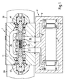
- the two-stage proportional control valve comprises a pilot stage or valve 1 and a main stage or valve 2.
- the main stage 2 (shown diagrammatically) comprises a body 3 in which is slidably mounted a spool 4 of overlapped construction, the body comprising two end chambers 5 and 6 to which pressure fluid can be applied through respective channels or drillings 7 and 8 from the pilot valve 1.
- Two centring springs 9 act on respective ends of the spool 4 in conventional manner.
- the pilot valve 1 is of zero lapped construction and comprises a body 11 in which is slidably mounted a spool 12 formed from two separable portions 13,14 urged apart by a spring 15.
- Each portion 13,14 of the pilot spool 12 has a through bore 16 and a counter bore 17 at the adjacent ends of the two portions, in which counter bores the respective ends of the spring 15 are accommodated.
- the outer end of each spool portion 13,14 is acted upon by a centring or return spring 18, the rate and preload of the spring 15 being sufficient to overcome the action of the centring springs 18.
- the centring springs 18 are accommodated in respective end chambers 19 and act between one end of the chamber and washer 21.
- each through bore 16 connects with a radial bore 22 which in all positions of the pilot spool is in communication with the corresponding tank port 23,24, the tank ports being interconnected by a gallery or loop 25.
- Drillings 20 in the body 11 connect the end chambers 19 to tank.
- a central pressure or supply port 26 is provided on each side of which is provided a service port 27 and 28 which themselves are disposed between the tank port 23 and 24.
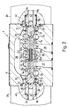
- the pressure port 26 is in fact divided into two ports 26a and 26b by a sleeve 29 which is inserted into the bore of the pilot body 11 and retained in position by spring washers 31. It will be seen that the sleeve 29 has apertures in alignment with the tank ports 23 and 24 and the service port 27 and 28.
- the pilot spool 12 has a composite central land 32 made up from the adjacent ends 32a and 32b of the spool portions 13 and 14.
- the pilot spool 12 has end lands 33 provided on respective spool portions 13 and 14, and intermediate lands 34 disposed, in the null position of the valve, to provide a zero lapped condition between the service ports 27 and 28 and the associated tank ports 23 and 24.
- the outer ends of the pilot spool valve portions 13 and 14 each have a reduced end portion 35 providing a step against which the associated washer 21 sits.
- the ends of the sleeve 29 provide stops 36 for the washers 21, thereby limiting the operational range of the pilot spool 12.
- the end chambers 19 are made up of a recess 37 in the valve body 11 and a recess 38 in a housing 41 of a solenoid 39 attached and sealed, in conventional manner, to the end of the spool valve body.
- Each solenoid 39 has a push pin 42 which is in contact with the associated reduced diameter portion 35 of the pilot spool 12.
- both solenoids are energised to effect a push-pull action on the spool to move it in the required direction, so as in turn to move the spool 4 of the main stage or valve 2 to drive a load connected thereto in the required direction.
- the pressure ports 26a, 26b are zero lapped to the central lands 32a, 32b and the intermediate lands 34 are zero lapped to the tank ports 23 and 24, whereby the service ports 27 and 28 are, in the exact null position, blocked from the pressure port 26 and tank ports 23,24.
- the central land portion 32b moves across pressure port 26b so that flow can take place therethrough to the service port 28 and thence to the right-hand chamber 6 of the main valve 2, whereby the pressure fluid in that chamber moves the main spool 4 to the left.
- the intermediate land 34 on the pilot spool portion 13 opens the tank port 23 to the service port 27 and thus the left-hand chamber 5 of the main valve 2 to tank. If the pilot spool 12 is moved to the right, then the left-hand chamber 5 of the main valve 2 is pressurised and the right-hand chamber 6 vented to tank.
- the solenoid push pins 42 no longer exert a closing force on the pilot spool portions 13 and 14 whereupon the spring 15 is effective in separating the spool portions, overcoming the closing action of the centring springs 18 and 19.
- each end chamber 5 and 6 of the main stage valve 2 is quickly connected to tank, thus effecting a rapid centralisation of the main spool 4.
- hydraulic fluid fills the gap created therebetween, the fluid flowing through the through bores 16 and the radial bores 22, this fluid being at tank pressure.
- the end chambers 19 are also at tank pressure by virtue of the drillings 20 between those chambers and the tank loop or gallery 25, whereby the pilot valve spool 12 is pressure balanced. It will be understood that when the pilot valve resumes its normal operation and the two pilot spool portions 13 and 14 are moved back into contact with each other by the solenoid push pins 42, then hydraulic fluid is pumped to tank by this closing action again, through the through and radial bores 16 and 22.
- the present invention provides a normal, zero lapped pilot valve of conventional construction as regards the provision of pressure, tank and service ports but by splitting the service port into two service ports, quick and reliable fail-safe operation takes place, thus removing the conflict between required zero lap for normal operation, and underlap for fail-safe operation.
- the present invention thus afford a significant advance in the art.
Landscapes
- Engineering & Computer Science (AREA)
- General Engineering & Computer Science (AREA)
- Mechanical Engineering (AREA)
- Physics & Mathematics (AREA)
- Fluid Mechanics (AREA)
- Chemical & Material Sciences (AREA)
- Analytical Chemistry (AREA)
- Magnetically Actuated Valves (AREA)
- Multiple-Way Valves (AREA)
- Fluid-Driven Valves (AREA)
Applications Claiming Priority (2)
| Application Number | Priority Date | Filing Date | Title |
|---|---|---|---|
| GB9211898 | 1992-06-05 | ||
| GB929211898A GB9211898D0 (en) | 1992-06-05 | 1992-06-05 | Two-stage hydraulic valves |
Publications (2)
| Publication Number | Publication Date |
|---|---|
| EP0573191A1 true EP0573191A1 (de) | 1993-12-08 |
| EP0573191B1 EP0573191B1 (de) | 1995-06-28 |
Family
ID=10716575
Family Applications (1)
| Application Number | Title | Priority Date | Filing Date |
|---|---|---|---|
| EP93303989A Expired - Lifetime EP0573191B1 (de) | 1992-06-05 | 1993-05-21 | Zweistufige hydraulische Ventile |
Country Status (5)
| Country | Link |
|---|---|
| US (1) | US5385171A (de) |
| EP (1) | EP0573191B1 (de) |
| JP (1) | JP3208393B2 (de) |
| DE (1) | DE69300220T2 (de) |
| GB (1) | GB9211898D0 (de) |
Cited By (7)
| Publication number | Priority date | Publication date | Assignee | Title |
|---|---|---|---|---|
| EP0860612A3 (de) * | 1997-02-25 | 1999-05-12 | Lucas Industries Public Limited Company | Schieberventil mit regelbarer Überdeckung |
| WO2003031854A1 (en) * | 2001-10-11 | 2003-04-17 | Mico, Incorporated | Auto-relieving pressure modulating valve |
| WO2006105765A1 (de) | 2005-04-04 | 2006-10-12 | Bosch Rexroth Ag | Wegeventil und damit ausgeführte ls-steueranordnung |
| WO2008137986A1 (en) * | 2007-05-08 | 2008-11-13 | Raytheon Sarcos, Llc | Quantum fluid transfer system |
| WO2010022869A1 (de) * | 2008-08-28 | 2010-03-04 | Robert Bosch Gmbh | Ventil |
| CN101151464B (zh) * | 2005-08-09 | 2010-08-25 | 布鲁宁赫斯海诺马帝克有限公司 | 具有交替止动的控制阀单元 |
| EP3680530A4 (de) * | 2018-04-27 | 2021-06-09 | KYB Corporation | Kappe mit elektromagnetischem proportionalventil |
Families Citing this family (20)
| Publication number | Priority date | Publication date | Assignee | Title |
|---|---|---|---|---|
| US5769545A (en) * | 1996-12-04 | 1998-06-23 | Bently Nevada Corporation | Hydrostatic bearing for supporting rotating equipment, a fluid handling system associated therewith, a control system therefore, method and apparatus |
| US6142672A (en) * | 1998-06-22 | 2000-11-07 | Bently Nevada Corporation | Fluid flow and control system for a hydrostatic bearing supporting rotating equipment: method and apparatus |
| AT3017U3 (de) * | 1999-03-18 | 2000-03-27 | Hoerbiger Hydraulik | Steueranordnung für einen arbeitszylinder |
| US6457088B1 (en) | 1999-07-20 | 2002-09-24 | Vickers, Inc. | Method and apparatus for programming an amplifier |
| IT1311060B1 (it) * | 1999-12-14 | 2002-02-28 | Bucher Hidroirma S P A | Valvola di controllo direzionale. |
| DE102004016368B3 (de) * | 2004-04-02 | 2005-09-15 | Sauer-Danfoss (Neumünster) GmbH & Co OHG | Hydrostatische Verdrängereinheit mit einem Schwenkmechanismus und einer Servoeinheit mit Druckminderventilen |
| US7284471B2 (en) * | 2004-12-02 | 2007-10-23 | Sarcos Investments Lc | Pressure control valve having intrinsic mechanical feedback system |
| US7308848B2 (en) * | 2004-12-02 | 2007-12-18 | Sarcos Investments Lc | Pressure control valve having intrinsic feedback system |
| WO2008106618A1 (en) * | 2007-02-28 | 2008-09-04 | Raytheon Sarcos, Llc | Fluid control system having selective recruitable actuators |
| JP5232177B2 (ja) * | 2007-02-28 | 2013-07-10 | レイセオン カンパニー | 作動装置を能動的および受動的に作動させる対立する流体制御システム |
| US7779863B2 (en) * | 2007-06-29 | 2010-08-24 | Raytheon Sarcos, Llc | Pressure control valve having an asymmetric valving structure |
| CA2727794A1 (en) * | 2008-06-11 | 2009-12-17 | Qinghui Yuan | Auto-tuning electro-hydraulic valve |
| CN101893011A (zh) * | 2010-07-30 | 2010-11-24 | 三一重工股份有限公司 | 液压阀、液压阀组及其控制方法 |
| US10006541B2 (en) * | 2011-07-28 | 2018-06-26 | Ford Global Technologies, Llc | Regulator valve with integrated direct acting solenoid |
| CN103511376A (zh) * | 2012-06-19 | 2014-01-15 | 上海立新液压有限公司 | 一种高频响比例方向阀 |
| JP5848721B2 (ja) * | 2013-03-21 | 2016-01-27 | 川崎重工業株式会社 | 緩衝弁 |
| DE102013220279A1 (de) * | 2013-10-08 | 2015-04-23 | Deere & Company | Hydraulisches Wegeventil |
| CN104454747B (zh) * | 2014-12-05 | 2017-01-04 | 浙江大学 | 一种采用双三位三通比例阀结构的新型高频响先导阀 |
| JP6724925B2 (ja) * | 2015-09-24 | 2020-07-15 | 日立金属株式会社 | メカニカル継手及びその製造方法 |
| JP6815103B2 (ja) | 2016-06-10 | 2021-01-20 | 川崎重工業株式会社 | 流量制御弁装置 |
Citations (1)
| Publication number | Priority date | Publication date | Assignee | Title |
|---|---|---|---|---|
| US4617967A (en) * | 1982-12-13 | 1986-10-21 | Vickers, Incorporated | Two-stage hydraulic valves |
Family Cites Families (2)
| Publication number | Priority date | Publication date | Assignee | Title |
|---|---|---|---|---|
| DE3406794A1 (de) * | 1984-02-24 | 1985-09-05 | Mannesmann Rexroth GmbH, 8770 Lohr | Druckregelventil |
| JPS6469878A (en) * | 1987-09-10 | 1989-03-15 | Diesel Kiki Co | Solenoid proportional pressure control valve |
-
1992
- 1992-06-05 GB GB929211898A patent/GB9211898D0/en active Pending
-
1993
- 1993-05-21 EP EP93303989A patent/EP0573191B1/de not_active Expired - Lifetime
- 1993-05-21 DE DE69300220T patent/DE69300220T2/de not_active Expired - Lifetime
- 1993-05-25 JP JP14437793A patent/JP3208393B2/ja not_active Expired - Fee Related
- 1993-06-03 US US08/071,522 patent/US5385171A/en not_active Expired - Lifetime
Patent Citations (1)
| Publication number | Priority date | Publication date | Assignee | Title |
|---|---|---|---|---|
| US4617967A (en) * | 1982-12-13 | 1986-10-21 | Vickers, Incorporated | Two-stage hydraulic valves |
Cited By (13)
| Publication number | Priority date | Publication date | Assignee | Title |
|---|---|---|---|---|
| EP0860612A3 (de) * | 1997-02-25 | 1999-05-12 | Lucas Industries Public Limited Company | Schieberventil mit regelbarer Überdeckung |
| WO2003031854A1 (en) * | 2001-10-11 | 2003-04-17 | Mico, Incorporated | Auto-relieving pressure modulating valve |
| US6609538B2 (en) | 2001-10-11 | 2003-08-26 | Mico, Inc. | Auto-relieving pressure modulating valve |
| US6802330B2 (en) | 2001-10-11 | 2004-10-12 | Mico, Inc. | Auto-relieving pressure modulating valve |
| WO2006105765A1 (de) | 2005-04-04 | 2006-10-12 | Bosch Rexroth Ag | Wegeventil und damit ausgeführte ls-steueranordnung |
| CN101151464B (zh) * | 2005-08-09 | 2010-08-25 | 布鲁宁赫斯海诺马帝克有限公司 | 具有交替止动的控制阀单元 |
| US8245728B2 (en) | 2007-05-08 | 2012-08-21 | Raytheon Company | Quantum fluid transfer system |
| CN101688615B (zh) * | 2007-05-08 | 2012-07-04 | 雷神萨科斯公司 | 量子流体传输系统 |
| WO2008137986A1 (en) * | 2007-05-08 | 2008-11-13 | Raytheon Sarcos, Llc | Quantum fluid transfer system |
| US8794262B2 (en) | 2007-05-08 | 2014-08-05 | Raytheon Company | Quantum fluid transfer system |
| WO2010022869A1 (de) * | 2008-08-28 | 2010-03-04 | Robert Bosch Gmbh | Ventil |
| EP3680530A4 (de) * | 2018-04-27 | 2021-06-09 | KYB Corporation | Kappe mit elektromagnetischem proportionalventil |
| US11262768B2 (en) | 2018-04-27 | 2022-03-01 | Kyb Corporation | Cap with electromagnetic proportional valve |
Also Published As
| Publication number | Publication date |
|---|---|
| US5385171A (en) | 1995-01-31 |
| GB9211898D0 (en) | 1992-07-15 |
| EP0573191B1 (de) | 1995-06-28 |
| JPH06129567A (ja) | 1994-05-10 |
| DE69300220T2 (de) | 1995-12-21 |
| DE69300220D1 (de) | 1995-08-03 |
| JP3208393B2 (ja) | 2001-09-10 |
Similar Documents
| Publication | Publication Date | Title |
|---|---|---|
| EP0573191B1 (de) | Zweistufige hydraulische Ventile | |
| US4615358A (en) | Pilot valves for two-stage hydraulic devices | |
| US4617967A (en) | Two-stage hydraulic valves | |
| US4903727A (en) | Safety valve | |
| US5343703A (en) | Control apparatus of control surface of aircraft | |
| US4825748A (en) | Hydraulic actuator synchronization apparatus and system | |
| EP0607903B1 (de) | Stromventil mit Vorsteuerung und Druckkompensation | |
| EP0110501B1 (de) | Redundant gesteuertes Stellsystem für ein direkt angetriebenes konzentrisches Ventil | |
| US4473095A (en) | Hydraulic valve | |
| EP0982503B1 (de) | Servobetätigter Kolben mit autarker, hydromechanischer Meldung | |
| US4903729A (en) | Safety valve | |
| US4903728A (en) | Safety valve | |
| US3358711A (en) | Valve | |
| EP1088740A3 (de) | Ausfallsicherer Kreislauf bei einer Vierradlenkung | |
| EP4402380B1 (de) | Redundantes hydraulisches system | |
| US4534273A (en) | Control actuation system including staged direct drive valve with fault control | |
| EP0396760B1 (de) | Steuerungsventil | |
| EP0128003A2 (de) | Zweistufiges richtungsabhängiges Regelventil | |
| JPH0447166B2 (de) | ||
| EP0860612B1 (de) | Schieberventil mit regelbarer Überdeckung | |
| EP0359354B1 (de) | Fluid-Steuerventil mit variabler Druckverstärkung | |
| GB2053419A (en) | Hydraulic Control Apparatus | |
| US5467688A (en) | Operating valve device | |
| US4637294A (en) | Device for controlling the supply of fluid under pressure to a hydrauic circuit as a function of the state of locking of unlocking of two mechanical members | |
| CA1203145A (en) | Control actuation system including staged direct drive valve with fault control |
Legal Events
| Date | Code | Title | Description |
|---|---|---|---|
| PUAI | Public reference made under article 153(3) epc to a published international application that has entered the european phase |
Free format text: ORIGINAL CODE: 0009012 |
|
| AK | Designated contracting states |
Kind code of ref document: A1 Designated state(s): DE GB IT |
|
| 17P | Request for examination filed |
Effective date: 19940430 |
|
| 17Q | First examination report despatched |
Effective date: 19940726 |
|
| GRAA | (expected) grant |
Free format text: ORIGINAL CODE: 0009210 |
|
| AK | Designated contracting states |
Kind code of ref document: B1 Designated state(s): DE GB IT |
|
| PG25 | Lapsed in a contracting state [announced via postgrant information from national office to epo] |
Ref country code: IT Free format text: LAPSE BECAUSE OF FAILURE TO SUBMIT A TRANSLATION OF THE DESCRIPTION OR TO PAY THE FEE WITHIN THE PRE;WARNING: LAPSES OF ITALIAN PATENTS WITH EFFECTIVE DATE BEFORE 2007 MAY HAVE OCCURRED AT ANY TIME BEFORE 2007. THE CORRECT EFFECTIVE DATE MAY BE DIFFERENT FROM THE ONE RECORDED.SCRIBED TIME-LIMIT Effective date: 19950628 |
|
| REF | Corresponds to: |
Ref document number: 69300220 Country of ref document: DE Date of ref document: 19950803 |
|
| PLBE | No opposition filed within time limit |
Free format text: ORIGINAL CODE: 0009261 |
|
| STAA | Information on the status of an ep patent application or granted ep patent |
Free format text: STATUS: NO OPPOSITION FILED WITHIN TIME LIMIT |
|
| 26N | No opposition filed | ||
| REG | Reference to a national code |
Ref country code: GB Ref legal event code: IF02 |
|
| PGFP | Annual fee paid to national office [announced via postgrant information from national office to epo] |
Ref country code: DE Payment date: 20120531 Year of fee payment: 20 |
|
| PGFP | Annual fee paid to national office [announced via postgrant information from national office to epo] |
Ref country code: GB Payment date: 20120426 Year of fee payment: 20 |
|
| REG | Reference to a national code |
Ref country code: DE Ref legal event code: R071 Ref document number: 69300220 Country of ref document: DE |
|
| REG | Reference to a national code |
Ref country code: GB Ref legal event code: PE20 Expiry date: 20130520 |
|
| PG25 | Lapsed in a contracting state [announced via postgrant information from national office to epo] |
Ref country code: GB Free format text: LAPSE BECAUSE OF EXPIRATION OF PROTECTION Effective date: 20130520 Ref country code: DE Free format text: LAPSE BECAUSE OF EXPIRATION OF PROTECTION Effective date: 20130522 |