EP0573355A1 - Block zur Verbindung bzw. Montage von Profilstäben und daraus hergestelle Montage von Profilstäben - Google Patents
Block zur Verbindung bzw. Montage von Profilstäben und daraus hergestelle Montage von Profilstäben Download PDFInfo
- Publication number
- EP0573355A1 EP0573355A1 EP93401410A EP93401410A EP0573355A1 EP 0573355 A1 EP0573355 A1 EP 0573355A1 EP 93401410 A EP93401410 A EP 93401410A EP 93401410 A EP93401410 A EP 93401410A EP 0573355 A1 EP0573355 A1 EP 0573355A1
- Authority
- EP
- European Patent Office
- Prior art keywords
- holes
- block according
- face
- bars
- faces
- Prior art date
- Legal status (The legal status is an assumption and is not a legal conclusion. Google has not performed a legal analysis and makes no representation as to the accuracy of the status listed.)
- Granted
Links
Images



Classifications
-
- F—MECHANICAL ENGINEERING; LIGHTING; HEATING; WEAPONS; BLASTING
- F16—ENGINEERING ELEMENTS AND UNITS; GENERAL MEASURES FOR PRODUCING AND MAINTAINING EFFECTIVE FUNCTIONING OF MACHINES OR INSTALLATIONS; THERMAL INSULATION IN GENERAL
- F16B—DEVICES FOR FASTENING OR SECURING CONSTRUCTIONAL ELEMENTS OR MACHINE PARTS TOGETHER, e.g. NAILS, BOLTS, CIRCLIPS, CLAMPS, CLIPS OR WEDGES; JOINTS OR JOINTING
- F16B7/00—Connections of rods or tubes, e.g. of non-circular section, mutually, including resilient connections
- F16B7/18—Connections of rods or tubes, e.g. of non-circular section, mutually, including resilient connections using screw-thread elements
- F16B7/187—Connections of rods or tubes, e.g. of non-circular section, mutually, including resilient connections using screw-thread elements with sliding nuts or other additional connecting members for joining profiles provided with grooves or channels
-
- E—FIXED CONSTRUCTIONS
- E04—BUILDING
- E04B—GENERAL BUILDING CONSTRUCTIONS; WALLS, e.g. PARTITIONS; ROOFS; FLOORS; CEILINGS; INSULATION OR OTHER PROTECTION OF BUILDINGS
- E04B2/00—Walls, e.g. partitions, for buildings; Wall construction with regard to insulation; Connections specially adapted to walls
- E04B2/74—Removable non-load-bearing partitions; Partitions with a free upper edge
- E04B2/76—Removable non-load-bearing partitions; Partitions with a free upper edge with framework or posts of metal
-
- F—MECHANICAL ENGINEERING; LIGHTING; HEATING; WEAPONS; BLASTING
- F16—ENGINEERING ELEMENTS AND UNITS; GENERAL MEASURES FOR PRODUCING AND MAINTAINING EFFECTIVE FUNCTIONING OF MACHINES OR INSTALLATIONS; THERMAL INSULATION IN GENERAL
- F16B—DEVICES FOR FASTENING OR SECURING CONSTRUCTIONAL ELEMENTS OR MACHINE PARTS TOGETHER, e.g. NAILS, BOLTS, CIRCLIPS, CLAMPS, CLIPS OR WEDGES; JOINTS OR JOINTING
- F16B2200/00—Constructional details of connections not covered for in other groups of this subclass
- F16B2200/40—Clamping arrangements where clamping parts are received in recesses of elements to be connected
- F16B2200/403—Threaded clamping parts
-
- Y—GENERAL TAGGING OF NEW TECHNOLOGICAL DEVELOPMENTS; GENERAL TAGGING OF CROSS-SECTIONAL TECHNOLOGIES SPANNING OVER SEVERAL SECTIONS OF THE IPC; TECHNICAL SUBJECTS COVERED BY FORMER USPC CROSS-REFERENCE ART COLLECTIONS [XRACs] AND DIGESTS
- Y10—TECHNICAL SUBJECTS COVERED BY FORMER USPC
- Y10T—TECHNICAL SUBJECTS COVERED BY FORMER US CLASSIFICATION
- Y10T403/00—Joints and connections
- Y10T403/46—Rod end to transverse side of member
- Y10T403/4602—Corner joint
Definitions
- the present invention relates to the field of connection and assembly of profiled bars and it relates, more specifically, to the field of profiled bars with polygonal cross section and comprising, on at least one of their longitudinal face, a open T-slot.
- profiled bars of circular or polygonal section which are made of many different materials and which are intended to allow the construction and erection of various structures which can range from scaffolding or similar to load-bearing structures of a temporary or permanent nature, up to machine frames of a modular or non-modular nature.
- Such means suffer from all the above drawbacks and cannot be considered to offer a rapid, safe and efficient assembly and erection capacity. Such means pose, moreover, practical problems when the assembly must take place on a site where an auxiliary energy, such as electricity, is lacking for the supply of the machining devices.
- the object of the invention is to overcome the above drawbacks by proposing a single connection and assembly block for different connection modes capable of occurring between profiled bars, such as for example an end-to-end connection, a link in two parallel planes or a link in the same plane.
- the object of the invention is designed to also allow the constitution of assembly nodes from a number of bars greater than two or even bars whose cross section represents an integer multiple of the same constructive module of based.
- Another object of the invention is to propose a connection block requiring no prior machining both on itself and on the bars to be assembled and allowing a quick, efficient, positive connection to be made, without additional energy and by simple interlocking and screwing.
- Another object of the invention is to propose a block of connection and assembly which can be obtained easily by molding, for example in shell, without requiring significant operations to resume secondary machining.
- An additional object of the invention is to propose a connection and assembly block which fits into the profile of the bars to be assembled, so as to allow connection nodes of the same size to be obtained as the cross section of the bars and offering, in addition, an aesthetic character which, if not fundamental for the technical characteristics of the connection and assembly carried out, nevertheless allows the construction and erection of taut and pure line structures, susceptible to offer flat faces, suitable in particular for constituting support benches for the construction of sets of machines or installations of a modular nature or not.
- connection and assembly block according to the invention lies in the fact that its implementation and its adaptation can be carried out quickly by personnel not specially highly qualified, which makes it possible to reduce the overall cost of creation. , realization, construction of a structure based on profiled bars.
- the invention also relates to an assembly of profiled bars produced by means of at least one block of the above type.
- Fig. 1 is an exploded perspective of a node for assembling and connecting two profiled bars, from a block according to the invention.
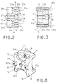
- Figs. 2 and 3 are sections taken respectively along planes II-II and III-III of FIG. 1.
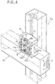
- Figs. 4, 5, 6 and 7 are perspectives illustrating four examples of assembly of profiled bars by means of the block according to the invention.
- Fig. 8 is a perspective similar to FIG. 1 illustrating an alternative embodiment.
- Fig. 9 is an exploded perspective of another embodiment.
- connection and assembly block is designed to allow the constitution of assembly nodes between elements of profiled bars, such as B1 and B2 , having an identical or similar construction and structure.
- each bar B1 or B2 is of the cross-section type, polygonal, preferably square or rectangular and comprises, on at least one face lateral 1 , at least one inverted T-shaped groove 2 , the inlet 3 of which is delimited by two rectilinear edges 4 facing each other and having a thickness e , preferably, constant.
- the bars B1 and B2 may have only one T-groove or, as illustrated in the drawings, a T-groove for each of the longitudinal faces, or even several for each face.
- Each bar B1 or B2 may also comprise, during manufacture or by subsequent recovery, at least one passage 5 , for example axial, of constant cross section.
- connection and assembly block consists of a solid body 10 , of generally rectangular parallelepiped shape, defining two lateral faces 11 and 12 having a geometric conformation which is preferably the same as the cross section the bar B1 or B2 bar.
- the solid body 10 thus has a periphery consisting of four faces 13 to 16 meeting at a right angle in the example illustrated and defining the thickness of the solid body 10 .
- Figs. 2 and 3 show in more detail that the solid body 10 is pierced in its thickness and at its center with a through bore 17 which opens on the face 12 by a counterbore 18 .
- the through bore 17 is formed in coordinates which allow coincidence with the passage 5 , when the block is arranged at the end of the bar B1 or B2 .
- the through bore is made in the center of the cross section of the block.
- the bore 17 and the counterbore 18 are reserved for mounting a self-tapping screw with head 19 intended to ensure possible fixing, at the end of the bar element B1 , for example, by self-tapping engagement of the screw 19 in the passage axial 5 .
- the lateral face 11 of the solid body 10 is then applied to the transverse face at the end of the bar element B1 .
- the solid body 10 is pierced in two orthogonal planes, such as the planes II and III, with two series of through holes 20a and 20b which, in the example illustrated, are provided, for each series, at equal distance, on either side of the axial bore 17 .
- the holes 20a of the first series are preferably reserved for mounting screws 21a cooperating beyond the face 12 with one or more lardon nuts 22a , the conformation of which is chosen so that they can be engaged inside a groove in T 2 behind the longitudinal edges 4 .
- the lardon nuts 22a can thus be provided individually for each screw 20a or, on the contrary, be produced in the form of a single bar having two internal threads capable of receiving the two screws 21a simultaneously.
- the holes 20a open through counterbores 23a in access openings 24a which are formed in the solid block 10 , from the side face 12 opposite to that offering the counterbore 18 of the central bore 17 , for s '' open on the transverse faces 14 and 16 .
- the holes 20b of the second series orthogonal to the first are, in a first example, constituted by threaded through passages which open on the two lateral faces 11 and 12 and which are intended to receive screws 25b whose axial length is, in an exemplary embodiment, close to but at most equal to the thickness of the solid body 10 .
- At least one of the lateral faces 11 , 12 and, preferably, both, has, in relief and in alignment with the corresponding contour faces, projections whose width is equal to the clearance of near penetration, at the width of the entrances 3 and whose thickness is equal to the thickness e .
- the projections, bearing the references 26 and 27 , respectively for the faces 11 and 12 are constituted by prismatic masses which are preferably two in number for each face, being aligned with one another and formed in correspondence with the series of holes. , that is to say with the series of holes 20a for the face 11 and with the series of holes 20b for the face 12 and being centered on the planes II and III.
- the face 11 devoid of the clearances 24a has notches 28 of conjugate conformation to the prismatic masses 27 and formed in a manner homologous to the latter.
- the block described above makes it possible to carry out different types of assembly, an example of which is illustrated in FIG. 1 .
- the block 10 can be adapted on the bar element B1 by being placed at the end of this element, so that an angular connection is established by the engagement of the projection (s) 27 in the corresponding grooves 2 , when by example the bar element B1 has a groove 2 on each of its longitudinal faces.
- the axial connection is ensured by mounting the screw 19 in the hole 17 , so as to ensure engagement by self-tapping in the passage 5 allowing effective immobilization tightening. A positive axial and angular connection is thus established.
- the assembly with the bar element B2 involves the engagement of the bar or lardon nuts 22a in the T-groove offered by the face of the element B2 opposite.
- the prismatic masses 26 can then be engaged in this groove, so that the screws 21a can cooperate with the bar or the lardon nuts 22a to tighten the lateral face 11 of the block 10 against the corresponding longitudinal face of the bar element B2 with effective nipping of the edges 4 between the lardon nuts 22a and the face 11 .
- the assembly node thus produced, has the same size as the cross section of the bar elements B1 and B2 and that it can be obtained by simple interlocking and screwing operations.
- the screws 21a are easily accessible via the clearances 24a and can thus be driven in rotation over a partial angular range, but nevertheless significant, due to the opening or the outlet of each clearance 24a on the transverse faces 14 and 16 . It is the same for the screws 25b accessible directly from the T-shaped grooves 2 .
- Fig. 4 shows another example of connection and possible assembly between the elements B1 and B2 , then arranged in two parallel planes.
- the block 10 can be mounted for example on the bar element B2 , by means of the screws 25b , the length of which, greater than the thickness of the block, allows cooperation with lardon nuts 29b ( Fig. 3 ) which are engaged in the groove 2 of the corresponding face of the bar B2 .
- the lardon nuts 29b can also be replaced by a bar having two tapped holes.
- the tapped holes 20b are replaced by smooth holes or the screws 25b are chosen with a diameter just smaller than that of the holes 20b to allow free axial movement.
- the bar element B1 is then fixed to the block 10 by means of the screws 21a cooperating with the lardon nuts 22a .
- the screw 19 is not mounted. It could, however, be envisaged, in certain cases, to ensure the connection of the body 10 on the bar element B2 , only by means of the screw 19 brought to cooperate with a lardon nut engaged in the groove 2 , by which the block is immobilized angularly by penetration of the prismatic masses 27 .
- the solid block 10 makes it possible to constitute a knot whose size, apart from the desired plane shift between the bar elements B1 and B2 , fits exactly in the cross section of said elements.
- Fig. 5 shows an example of implementation of the object of the invention to establish the connection between a bar element B1 and two bar elements B2 arranged side by side.
- a node is obtained by then using two connection blocks 10 which are mounted at the end of the two bar elements B2 , as said above, so that they can then be fixed by the two extreme screws 21a on the bar element B1 .
- the two bar elements B2 can be independent and separate or even constitute a single bar element whose transverse module is twice the unitary element described with reference to FIG. 1 .
- Fig. 6 shows another variant, from two blocks 10 arranged at the end of two simple B2 bar elements or a double B2 bar element, to establish a connection node with a B1 bar element having in cross section a double module of the element, according to FIG. 1 , and offering on a longitudinal face two inverted T-grooves 2 .
- the references given in FIG. 6 are used to determine the mounting orientation of the two bodies 10 which are first of all adapted at the end of the bar element (s) B2 .
- Fig. 7 shows another example of assembly in which the bar elements B1 and B2 , of the type of FIG. 1 , must be assembled end to end.
- each bar element receives a solid body 10 mounted by means of the screw 19 , so that each of them is applied at the end of the corresponding bar element by the face 12 .
- each solid body 10 is carried out with a 90 ° offset, so as to make the prismatic masses 26 of one of the solid bodies 10 cooperate, by relative mutual engagement, with the notches 28 of the solid body opposite. .
- the bar elements B1 and B2 are then placed end to end to be linked by the installation of screws 21a screwed into the holes 20b .
- Fig. 8 shows an alternative embodiment consisting in providing clearances 30 b in the face 11 by adopting an offset of 90 ° relative to the clearances 24a , so that the clearances 30b open on the transverse faces 13 and 15 .
- FIG. 4 shows an alternative embodiment consisting in providing in the face 11 , for example, a recess 40 leaving a peripheral edge 41 which is favorable to the establishment of good support of the face 11 on the longitudinal face of the element B1 , for example.
- the holes 20b can open into negative impressions 42 formed in the bottom of the recess 40 and, for example hexagonal, to receive captive nuts crimped for mounting the screws 25b .
- Fig. 9 shows an alternative embodiment of the object of the invention adapted to the connection of bars B1 and B2 which have several grooves 2 on at least one longitudinal face and, preferably but not exclusively, two on each of them.
- each sector or quadrant of the cross section, including a longitudinal edge has the same conformation as that of the example in FIG. 1 .
- the intersection of the planes P1 and P2 passing through the grooves, located on either side of the same edge defines the axis of a passage 50 similar to the passage 5 .
- connection and assembly block 10 then comprises, on the basis of the initial example but in adaptation to the cross section of the bars B1 and B2 of the example according to the Fig. 2 , two double series of through holes 20a1 and 20a2 provided on planes II1 and II2 and 20b1 and 20b2 provided on planes III plans and III2.
- the holes 20a1 and 20a2 correspond to the clearances 24a1 and 24a2 , as well as the prismatic masses 261 and 262 .
- the holes 20b1 and 20b2 correspond to the prismatic masses 271 and 272 , as well as the notches 281 and 282 .
- the block 10 according to this example also comprises through bores 60 which are arranged to be placed in coincidence with the passages 50 and allow the mounting of screws 19 engaging by self-tapping in said passages.
Landscapes
- Engineering & Computer Science (AREA)
- General Engineering & Computer Science (AREA)
- Architecture (AREA)
- Mechanical Engineering (AREA)
- Physics & Mathematics (AREA)
- Electromagnetism (AREA)
- Civil Engineering (AREA)
- Structural Engineering (AREA)
- Mutual Connection Of Rods And Tubes (AREA)
- Joining Of Building Structures In Genera (AREA)
Applications Claiming Priority (2)
| Application Number | Priority Date | Filing Date | Title |
|---|---|---|---|
| FR9206941A FR2692010B1 (fr) | 1992-06-03 | 1992-06-03 | Bloc de liaison et d'assemblage pour barres profilees et assemblage de barres en faisant application. |
| FR9206941 | 1992-06-03 |
Publications (2)
| Publication Number | Publication Date |
|---|---|
| EP0573355A1 true EP0573355A1 (de) | 1993-12-08 |
| EP0573355B1 EP0573355B1 (de) | 1997-03-12 |
Family
ID=9430546
Family Applications (1)
| Application Number | Title | Priority Date | Filing Date |
|---|---|---|---|
| EP93401410A Expired - Lifetime EP0573355B1 (de) | 1992-06-03 | 1993-06-02 | Block zur Verbindung bzw. Montage von Profilstäben und daraus hergestelle Montage von Profilstäben |
Country Status (4)
| Country | Link |
|---|---|
| US (1) | US5481842A (de) |
| EP (1) | EP0573355B1 (de) |
| DE (1) | DE69308642T2 (de) |
| FR (1) | FR2692010B1 (de) |
Cited By (3)
| Publication number | Priority date | Publication date | Assignee | Title |
|---|---|---|---|---|
| DE4430829A1 (de) * | 1994-08-31 | 1996-03-07 | Bumat Bewegungssysteme Gmbh | Selbstjustierende Schraubverbindung für zwei Profilteile |
| DE20210133U1 (de) * | 2002-07-01 | 2003-11-13 | Bosch Rexroth AG, 70173 Stuttgart | Verbindung von Profilstreben |
| EP2113618A1 (de) * | 2008-04-30 | 2009-11-04 | Trenzametal, S.L. | Elemente zum Erstellen von Metallzaun und Geländer von herkömmlich vorgefertigten Profilstäben sowie deren Montage |
Families Citing this family (43)
| Publication number | Priority date | Publication date | Assignee | Title |
|---|---|---|---|---|
| CA2115787C (en) * | 1993-10-22 | 2002-05-28 | Dale R. Marshall | Frame system for power and signal cable management |
| DE19520892A1 (de) * | 1995-06-08 | 1996-12-12 | Heron Sondermaschinen Und Steu | Plattenverbinder |
| DE29612106U1 (de) * | 1996-07-11 | 1996-09-12 | Knürr-Mechanik für die Elektronik AG, 81829 München | Tragsystem für Arbeitsmöbel |
| US5729948A (en) * | 1996-08-29 | 1998-03-24 | Levy; Tzadok | Apparatus and method for rigidly joining construction elements to one another |
| US5848500A (en) * | 1997-01-07 | 1998-12-15 | Eastman Kodak Company | Light-tight enclosure and joint connectors for enclosure framework |
| DE29705977U1 (de) * | 1997-04-04 | 1998-10-08 | Ramsauer, Dieter, 42555 Velbert | Anschraubscharnier für hinterschnittene Nuten aufweisende Profile |
| DE29720486U1 (de) * | 1997-11-19 | 1998-01-08 | Robert Bosch Gmbh, 70469 Stuttgart | Befestigungswinkel |
| EP0987450B1 (de) * | 1998-09-18 | 2002-12-04 | FMS Förder- und Montage-Systeme Schmalzhofer GmbH | Verbindungseinrichtung zum Verbinden von Profilstäben |
| US6712543B1 (en) * | 1999-07-21 | 2004-03-30 | Fms Forder-Und Montage-Systeme Schmalzhofer Gmbh | Connecting device for profiled bars with grooves |
| US20030101677A1 (en) * | 2000-07-12 | 2003-06-05 | Hewett Frank W. | Joining system for tubular members |
| EP1321592A1 (de) * | 2001-12-21 | 2003-06-25 | Paolo Manzi | Modulare Struktur für ein tragendes Rahmenwerk mit Profilkörpern und selbsttragenden Platten und Herstellungsverfahren dafür |
| US6848230B2 (en) * | 2002-12-11 | 2005-02-01 | Krueger International, Inc. | Connection arrangement for securing frame members together in a wall system |
| US20060104741A1 (en) * | 2004-11-17 | 2006-05-18 | Richard Schutz | Bolted fastener for joining components |
| ITBS20040144A1 (it) * | 2004-12-01 | 2005-03-01 | Gimatic Spa | Profilato multivalente per la composizione di telai, supporti, strutture portanti e simili |
| USD563768S1 (en) * | 2005-01-04 | 2008-03-11 | Marino Paul W | Grid bar for modular fixturing |
| US7654059B2 (en) * | 2006-03-16 | 2010-02-02 | Hejnicki Thomas L | Truss connector |
| US7753350B2 (en) * | 2006-10-09 | 2010-07-13 | Barziza Samuel W | T-slot block modules for milling machines and method of use |
| US7793367B1 (en) * | 2007-01-16 | 2010-09-14 | R.T. London Company | Furniture post and coupler |
| US8585000B2 (en) | 2008-05-22 | 2013-11-19 | Mainstream Energy Corporation | Universal end clamp |
| GB2472199B (en) * | 2009-07-27 | 2013-05-08 | Barco Nv | Spacer plate and support structure |
| AU2010219354A1 (en) * | 2009-10-20 | 2011-05-12 | Open Building Solutions Limited | Joinery connection assembly |
| CN105909636B (zh) * | 2010-04-26 | 2019-07-30 | 布兰金系统公司 | 用于使框架构架机械互锁的弯角件 |
| CN102316697A (zh) * | 2010-07-09 | 2012-01-11 | 鸿富锦精密工业(深圳)有限公司 | 机柜框架 |
| US8453402B2 (en) * | 2011-04-29 | 2013-06-04 | Rong-Jun Huang | Frame unit of a curtain wall |
| KR101115332B1 (ko) * | 2011-06-01 | 2012-03-06 | 정재은 | 알루미늄 프로파일의 연결구 |
| DE102011109848A1 (de) * | 2011-08-09 | 2013-02-14 | Airbus Operations Gmbh | Grundkörper, Gerüstsystem sowie Herstellungsverfahren für einen derartigen Grundkörper |
| USD708353S1 (en) | 2011-11-11 | 2014-07-01 | Blanking Systems, Inc. | Frame member |
| KR101253462B1 (ko) * | 2012-10-22 | 2013-04-10 | 재 욱 한 | 진열대용 수직프레임 및 이를 이용한 다용도 조립식 진열대 |
| KR101304138B1 (ko) * | 2013-06-05 | 2013-09-05 | 상욱 김 | 스테이지 설치용 프레임 연결 구조물 |
| US9022712B2 (en) | 2013-07-17 | 2015-05-05 | II James W. Klopfenstein | Fastener for attaching objects to channeled members |
| CN103821804A (zh) * | 2013-10-26 | 2014-05-28 | 芜湖长启炉业有限公司 | 中心发泡铝板专用四方连接柱 |
| EP2944832B1 (de) | 2014-04-23 | 2016-11-09 | Alusic S.r.l. | Montagesystem für abschnitte |
| DE202014104524U1 (de) * | 2014-09-22 | 2016-01-05 | Hartmut Flaig | Profilstab sowie Profilverbindung |
| US10260227B2 (en) * | 2015-06-09 | 2019-04-16 | Rock West Composites, Inc. | Tubular framing system and method |
| US10006212B2 (en) * | 2015-11-24 | 2018-06-26 | Sheng-Liang Chen | Assembled house |
| US10331806B2 (en) * | 2016-03-15 | 2019-06-25 | Peri Gmbh | Method for providing and assembling scaffolding units, each of which will be assembled from individual scaffolding components for constructing an industrial plant, in particular a petroleum refinery |
| CN105821964A (zh) * | 2016-04-07 | 2016-08-03 | 苏州罗普斯金铝业股份有限公司 | 一种铝合金型材 |
| CN106949358B (zh) * | 2017-02-22 | 2019-05-10 | 佛山市中卓精密五金制造有限公司 | 一种具有调节位置的铝合金支撑座 |
| PL3461963T3 (pl) * | 2017-09-29 | 2024-01-22 | Leviat GmbH | Układ nośny i układ elementów łączących do połączenia belek |
| US10925178B2 (en) * | 2019-04-04 | 2021-02-16 | Bell Helicopter Textron Inc. | Avionic sliding rack |
| US11708173B2 (en) | 2019-08-08 | 2023-07-25 | Textron Innovations Inc. | Avionic sliding rack |
| GB2591465A (en) * | 2020-01-28 | 2021-08-04 | Quantum 3 | Connector |
| CN217001180U (zh) * | 2021-08-11 | 2022-07-19 | 浙江永强集团股份有限公司 | 一种帐篷用梁柱快速组装结构 |
Citations (5)
| Publication number | Priority date | Publication date | Assignee | Title |
|---|---|---|---|---|
| DE8604195U1 (de) * | 1986-02-17 | 1986-05-28 | RK, Rose + Krieger GmbH & Co KG industrielle Rohrspannsysteme, 4950 Minden | Vorrichtung zum lösbaren Verbinden von zwei winklig zueinander stehenden, im Querschnitt eckigen Profilstäben |
| EP0233525A1 (de) * | 1986-02-17 | 1987-08-26 | RK-Rose + Krieger GmbH & Co. Kommanditgesellschaft Verbindungs- und Positioniersysteme | Vorrichtung zum lösbaren Verbinden zweier Profilstäbe |
| DE3923578A1 (de) * | 1989-07-17 | 1991-01-24 | Rudolf Lehn | Verbindungselement fuer eine klemmverbindung von profilstaeben |
| FR2653836A1 (fr) * | 1989-10-27 | 1991-05-03 | Lefur Jean Paul | Systeme d'assemblage de profiles creux et structure portante obtenue. |
| EP0460360B1 (de) * | 1990-06-05 | 1993-09-08 | Phoenix Mecano Ag | Vorrichtung zum lösbaren Verbinden von zwei Profilstäben |
Family Cites Families (10)
| Publication number | Priority date | Publication date | Assignee | Title |
|---|---|---|---|---|
| US3265416A (en) * | 1962-06-08 | 1966-08-09 | Leonard O Downes | Structural framing system |
| GB1124373A (en) * | 1966-04-26 | 1968-08-21 | Eliahu Meiri | Constructional element and means for its connection |
| NO125497B (de) * | 1968-05-30 | 1972-09-18 | Aluminium Syst Ltd | |
| FR2237516A5 (en) * | 1973-07-10 | 1975-02-07 | Re Grange Francois | Construction of shelves using grooved sections - block projecting from one section is telescoped into second section |
| GB1503588A (en) * | 1975-07-03 | 1978-03-15 | Profiles & Tubes De L Est | Building frame structural elements and fixing members therefor |
| FR2600726B2 (fr) * | 1986-04-11 | 1988-11-10 | Chenel Guy | Dispositif d'assemblage d'ossature de stand pour exposition temporaire. |
| JPH0663526B2 (ja) * | 1989-12-26 | 1994-08-22 | 株式会社ダイフク | 型材の連結構造 |
| DE4016320C1 (de) * | 1990-05-21 | 1991-09-19 | Wolfgang Dipl.-Ing. Rixen | |
| DE9013802U1 (de) * | 1990-10-04 | 1990-12-06 | RK Rose + Krieger GmbH & Co. KG Verbindungs- und Positioniersysteme, 4952 Porta Westfalica | Vorrichtung zum lösbaren Verbinden zweier Profilstäbe |
| FR2669714A1 (fr) * | 1990-11-28 | 1992-05-29 | Hannes Paul | Poutrelle profilee creuse. |
-
1992
- 1992-06-03 FR FR9206941A patent/FR2692010B1/fr not_active Expired - Fee Related
-
1993
- 1993-06-02 DE DE69308642T patent/DE69308642T2/de not_active Expired - Fee Related
- 1993-06-02 EP EP93401410A patent/EP0573355B1/de not_active Expired - Lifetime
- 1993-06-03 US US08/070,530 patent/US5481842A/en not_active Expired - Fee Related
Patent Citations (5)
| Publication number | Priority date | Publication date | Assignee | Title |
|---|---|---|---|---|
| DE8604195U1 (de) * | 1986-02-17 | 1986-05-28 | RK, Rose + Krieger GmbH & Co KG industrielle Rohrspannsysteme, 4950 Minden | Vorrichtung zum lösbaren Verbinden von zwei winklig zueinander stehenden, im Querschnitt eckigen Profilstäben |
| EP0233525A1 (de) * | 1986-02-17 | 1987-08-26 | RK-Rose + Krieger GmbH & Co. Kommanditgesellschaft Verbindungs- und Positioniersysteme | Vorrichtung zum lösbaren Verbinden zweier Profilstäbe |
| DE3923578A1 (de) * | 1989-07-17 | 1991-01-24 | Rudolf Lehn | Verbindungselement fuer eine klemmverbindung von profilstaeben |
| FR2653836A1 (fr) * | 1989-10-27 | 1991-05-03 | Lefur Jean Paul | Systeme d'assemblage de profiles creux et structure portante obtenue. |
| EP0460360B1 (de) * | 1990-06-05 | 1993-09-08 | Phoenix Mecano Ag | Vorrichtung zum lösbaren Verbinden von zwei Profilstäben |
Cited By (4)
| Publication number | Priority date | Publication date | Assignee | Title |
|---|---|---|---|---|
| DE4430829A1 (de) * | 1994-08-31 | 1996-03-07 | Bumat Bewegungssysteme Gmbh | Selbstjustierende Schraubverbindung für zwei Profilteile |
| DE20210133U1 (de) * | 2002-07-01 | 2003-11-13 | Bosch Rexroth AG, 70173 Stuttgart | Verbindung von Profilstreben |
| US7004667B2 (en) | 2002-07-01 | 2006-02-28 | Bosch Rexroth Ag | Connection of streamlined-section struts |
| EP2113618A1 (de) * | 2008-04-30 | 2009-11-04 | Trenzametal, S.L. | Elemente zum Erstellen von Metallzaun und Geländer von herkömmlich vorgefertigten Profilstäben sowie deren Montage |
Also Published As
| Publication number | Publication date |
|---|---|
| DE69308642T2 (de) | 1997-10-02 |
| EP0573355B1 (de) | 1997-03-12 |
| FR2692010A1 (fr) | 1993-12-10 |
| US5481842A (en) | 1996-01-09 |
| DE69308642D1 (de) | 1997-04-17 |
| FR2692010B1 (fr) | 1996-02-09 |
Similar Documents
| Publication | Publication Date | Title |
|---|---|---|
| EP0573355B1 (de) | Block zur Verbindung bzw. Montage von Profilstäben und daraus hergestelle Montage von Profilstäben | |
| FR2594187A1 (fr) | Raccord en croix pour tubes croises | |
| EP1567097A1 (de) | Zwischenwirbelkäfig mit mittigem verankerungsblatt | |
| CH624728A5 (de) | ||
| EP0824199A1 (de) | Pleuelstange für Brennkraftmaschine | |
| FR2806114A1 (fr) | Brique d'encastrement | |
| FR3004067A1 (fr) | Profile, notamment metallique, destine a permettre une fixation d'un film sur une structure de serre et systeme de fixation d'un film sur une structure de serre comprenant un tel profile | |
| FR2773568A1 (fr) | Dispositif d'assemblage d'elements de structure, comportant une equerre modulable | |
| CA2530135C (fr) | Dispositif mecanique comprenant plusieurs pieces assemblees avec un positionnement relatif precis | |
| EP1544478B1 (de) | Zusammengesetzte Rohrschelle | |
| FR2888998A1 (fr) | Dispositif de support pour barres electriquement conductrices | |
| FR2760908A1 (fr) | Dispositif d'assemblage pour assembler des barres omnibus d'un jeu de barres | |
| FR2832602A1 (fr) | Meuble modulaire | |
| FR2650050A1 (fr) | Dispositif d'assemblage autobloquant de deux pieces cylindriques, pour realiser des rallonges de manches d'outil ou pour effectuer une fixation d'un tel outil sur son manche, notamment dans le domaine du ramonage | |
| FR2759209A1 (fr) | Liaison angulaire pour barres omnibus d'un jeu de barres | |
| FR2566478A1 (fr) | Dispositif pour l'assemblage d'elements de construction plans | |
| FR2587085A1 (fr) | Profiles et leurs pieces d'assemblage pour la confection, avec des panneaux, de cloisons et de mobiliers demontables et recuperables | |
| FR2621428A1 (fr) | Bloc modulaire de boites electriques universelles fractionnables | |
| FR2711745A1 (fr) | Etrier réglable. | |
| WO2000042327A1 (fr) | Systeme d'assemblage pour elements longiformes | |
| FR2624222A1 (fr) | Systeme modulaire d'assemblage d'elements de structure | |
| EP0801712A1 (de) | Flächen- und verteilte trägerkonstruktion | |
| FR2869080A1 (fr) | Elements de jonction et support pour constructions modulaires a montage rapide | |
| FR3114203A1 (fr) | Dispositif ajustable de panneaux solaires | |
| FR2760053A1 (fr) | Perfectionnements aux structures de meubles |
Legal Events
| Date | Code | Title | Description |
|---|---|---|---|
| PUAI | Public reference made under article 153(3) epc to a published international application that has entered the european phase |
Free format text: ORIGINAL CODE: 0009012 |
|
| AK | Designated contracting states |
Kind code of ref document: A1 Designated state(s): CH DE ES FR IT LI |
|
| 17P | Request for examination filed |
Effective date: 19940110 |
|
| 17Q | First examination report despatched |
Effective date: 19950328 |
|
| GRAG | Despatch of communication of intention to grant |
Free format text: ORIGINAL CODE: EPIDOS AGRA |
|
| GRAH | Despatch of communication of intention to grant a patent |
Free format text: ORIGINAL CODE: EPIDOS IGRA |
|
| GRAH | Despatch of communication of intention to grant a patent |
Free format text: ORIGINAL CODE: EPIDOS IGRA |
|
| GRAA | (expected) grant |
Free format text: ORIGINAL CODE: 0009210 |
|
| AK | Designated contracting states |
Kind code of ref document: B1 Designated state(s): CH DE ES FR IT LI |
|
| PG25 | Lapsed in a contracting state [announced via postgrant information from national office to epo] |
Ref country code: IT Free format text: LAPSE BECAUSE OF FAILURE TO SUBMIT A TRANSLATION OF THE DESCRIPTION OR TO PAY THE FEE WITHIN THE PRE;WARNING: LAPSES OF ITALIAN PATENTS WITH EFFECTIVE DATE BEFORE 2007 MAY HAVE OCCURRED AT ANY TIME BEFORE 2007. THE CORRECT EFFECTIVE DATE MAY BE DIFFERENT FROM THE ONE RECORDED.SCRIBED TIME-LIMIT Effective date: 19970312 Ref country code: ES Free format text: THE PATENT HAS BEEN ANNULLED BY A DECISION OF A NATIONAL AUTHORITY Effective date: 19970312 |
|
| REG | Reference to a national code |
Ref country code: CH Ref legal event code: EP |
|
| REF | Corresponds to: |
Ref document number: 69308642 Country of ref document: DE Date of ref document: 19970417 |
|
| PLBE | No opposition filed within time limit |
Free format text: ORIGINAL CODE: 0009261 |
|
| STAA | Information on the status of an ep patent application or granted ep patent |
Free format text: STATUS: NO OPPOSITION FILED WITHIN TIME LIMIT |
|
| 26N | No opposition filed | ||
| PGFP | Annual fee paid to national office [announced via postgrant information from national office to epo] |
Ref country code: CH Payment date: 19980701 Year of fee payment: 6 |
|
| PG25 | Lapsed in a contracting state [announced via postgrant information from national office to epo] |
Ref country code: LI Free format text: LAPSE BECAUSE OF NON-PAYMENT OF DUE FEES Effective date: 19990630 Ref country code: CH Free format text: LAPSE BECAUSE OF NON-PAYMENT OF DUE FEES Effective date: 19990630 |
|
| PGFP | Annual fee paid to national office [announced via postgrant information from national office to epo] |
Ref country code: DE Payment date: 19990701 Year of fee payment: 7 |
|
| REG | Reference to a national code |
Ref country code: CH Ref legal event code: PL |
|
| PG25 | Lapsed in a contracting state [announced via postgrant information from national office to epo] |
Ref country code: DE Free format text: LAPSE BECAUSE OF NON-PAYMENT OF DUE FEES Effective date: 20010403 |
|
| PGFP | Annual fee paid to national office [announced via postgrant information from national office to epo] |
Ref country code: FR Payment date: 20030619 Year of fee payment: 11 |
|
| PG25 | Lapsed in a contracting state [announced via postgrant information from national office to epo] |
Ref country code: FR Free format text: LAPSE BECAUSE OF NON-PAYMENT OF DUE FEES Effective date: 20050228 |
|
| REG | Reference to a national code |
Ref country code: FR Ref legal event code: ST |